

junki
-
Posts
7 -
Joined
-
Last visited
Recent Profile Visitors
1147 profile views

-
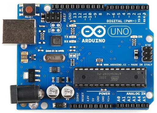
 Hello all. As the question, I want to use the arduino board to detect the distance in three directions at once. the code compiled, uploaded are no problem, but can only return the data on the left, the middle and right are returned 0 value, I will be the left sensor code blocked can only return the data of the middle sensor, the right is still 0 value, the left and middle are blocked can return the data on the right , that is, the three ultrasonic sensors can That is, the three sensors can work separately, but can not return data together. That you have experience in this area to share, the code is as follows. const int left_Trig = 1; const int left_Echo = 2; const int center_Trig = 3; const int center_Echo = 4; const int right_Trig = 5; const int right_Echo = 6; float a; float b; float c; void setup() { Serial.begin(9600); pinMode(left_Trig, OUTPUT); pinMode(center_Trig, OUTPUT); pinMode(right_Trig, OUTPUT); pinMode(left_Echo, INPUT); pinMode(center_Echo, INPUT); pinMode(right_Echo, INPUT); Serial.println("Ultrasonic sensor:"); } void loop() { digitalWrite(left_Trig, LOW); delayMicroseconds(2); digitalWrite(center_Trig, LOW); delayMicroseconds(2); digitalWrite(right_Trig, LOW); delayMicroseconds(2); digitalWrite(left_Trig, HIGH); delayMicroseconds(10); digitalWrite(center_Trig, HIGH); delayMicroseconds(10); digitalWrite(right_Trig, HIGH); delayMicroseconds(10); digitalWrite(left_Trig, LOW); digitalWrite(center_Trig, LOW); digitalWrite(right_Trig, LOW); a=pulseIn(left_Echo, HIGH) / 58.00; Serial.println(a); b=pulseIn(center_Echo, HIGH) / 58.00; Serial.println(b); c=pulseIn(right_Echo, HIGH) / 58.00; Serial.println(c); a = (int(a* 100.0)) / 100.0; b = (int(b* 100.0)) / 100.0; c = (int(c* 100.0)) / 100.0; Serial.println(a); Serial.println(b); Serial.println(c); Serial.println(); delay(10); }
-
Thank you for leaving this suggestion as I can try to plug the circuit in some simulator!!!
-
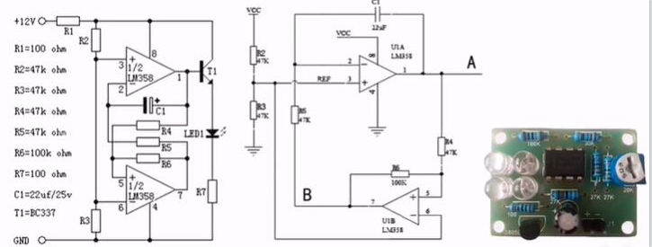
Can someone tell me what does R6 in this LM358 circuit diagram do? I guess R6 is part of the square wave generator that forms the b diagram. R6 accelerates the transition of the output state of the op amp through positive feedback to cross the indeterminate state, and acts as a Schmitt trigger. Guys do you agree?
-
I am using an ATX SMPS to power my Orange Pi Plus 2 via 5V supply. It worked fine for a couple of days without problem until yesterday. I happend to connect my audio amplifier TPA3116 which worked fine. After which when i was switching some cables i happend to short the 12V supply. The smps immediately shut itself down. Now i removed the short and disconnect the audio amplifier from 12V supply. After this when i started the orange pi there was no more any indication. I wanted to know that if the 12V short let to an inrush current spike at the 5V power section. If any one on this forum is aware of fuses present on the orange pi board.
-
I bought DS1307 RTC but it is 5V so it can't be connected to the Pi. I know it can be modified to use 3.3V by removing 2 resistors. This sensor is different than the adafruit kit so I am not sure which resistors to remove. It also has 2 sets of pins. What are the extra pins for and which should I use and which pins do I remove? Here is the image of the RTC: Here you can see the datasheet for the DS1307 RTC.
-
I am trying to use a DHT21 with a Lamobo R1 aka Banana PI R1 to read temperature and humidity, with Armbian/Jessie and a 4.5.2 kernel. A Lamobo R1 is basically an A20 board raspberry pi compatible, with an inverted compatible raspberry pi v2 bus. I have setup it up in GPIO5, raspberry pin compatible 24, WirinPi 5, physical pin 18, according to a table here, plus the GND and +5V pins. I tried to read the temperature and humidity with and without the recommended resistor. While the temperature is reading fine, and is also corroborated by a DS18b20 sensor connected to GPIO2, which indicates the setup is fine, the humidity is always at 99.9%. I have installed the WiringPi compatible library from WiringBP repository. However, using for instance DHT21-AM2301 or lol_dht22 I have got always the output of Humidity as 99.9% or 99.90% A custom kernel module for this chip, am2301 simply hangs the machine. What I have found until now is: It seems to work with Raspberry and Arduino; The chip is highly sensitive to timings, even in a raspberry; Some people did report it only worked in GPIO1 and GPIO2 in the original raspberry, whilst the other GPIOs had much greater latency; There is a much more complicated hardware setup to connect it to a I2C, in which I am not particularly interested; Some people also theorise it only works with kernel 3 (however I am reading temperature) Lamobo R1 seems to have a pullup pin bus by default; Readings can be done only every second; The physical implementation of the R1 bus relating to the rpi allow me to get without the resistor; the limit of cable seems to be 25m, and there are anecdotal tales of people achieving 60m with UTP cable. Mine is no longer than 20cm. Does anyone has anything else to add? Additional notes as per comments: Humidity comes first than temperature; as @ChrisStratton theorised, humidity bits are all 1; I have already tested two DHT21 sensors with the same results. The output of gpio readall is +----------+-Rev3-+------+--------+------+-------+ | wiringPi | GPIO | Phys | Name | Mode | Value | +----------+------+------+--------+------+-------+ | 0 | 17 | 11 | GPIO 0 | IN | Low | | 1 | 18 | 12 | GPIO 1 | IN | High | | 2 | 27 | 13 | GPIO 2 | IN | Low | | 3 | 22 | 15 | GPIO 3 | IN | Low | | 4 | 23 | 16 | GPIO 4 | IN | Low | | 5 | 24 | 18 | GPIO 5 | OUT | High | | 6 | 25 | 22 | GPIO 6 | IN | Low | | 7 | 4 | 7 | GPIO 7 | IN | Low | | 8 | 2 | 3 | SDA | ALT5 | High | | 9 | 3 | 5 | SCL | ALT5 | High | | 10 | 8 | 24 | CE0 | IN | Low | | 11 | 7 | 26 | CE1 | IN | Low | | 12 | 10 | 19 | MOSI | ALT5 | Low | | 13 | 9 | 21 | MISO | ALT5 | Low | | 14 | 11 | 23 | SCLK | ALT5 | Low | | 15 | 14 | 8 | TxD | ALT0 | Low | | 16 | 15 | 10 | RxD | ALT0 | Low | | 17 | 28 | 3 | GPIO 8 | IN | Low | | 18 | 29 | 4 | GPIO 9 | ALT4 | Low | | 19 | 30 | 5 | GPIO10 | OUT | High | | 20 | 31 | 6 | GPIO11 | ALT4 | Low | +----------+------+------+--------+------+-------+