

ej0rge
-
Posts
30 -
Joined
-
Last visited
Content Type
Forums
Store
Crowdfunding
Applications
Events
Raffles
Community Map
Posts posted by ej0rge
-
-
On 4/12/2021 at 1:01 PM, jernej said:
Can you give link to your exact model? Looking at waveshare site, 4.3" 480x272 LCD has only 40 pin connector - this will not work with anything but RPi. Or did you mean 4.3" 800x480 HDMI monitor? This one should work in theory. There is also 4.3" 800x480 DSI one which I'm not sure if it can work or not.
Minor quibble -- You can get the gpio displays to work, but you need a dtoverlay and you will probably have to write it yourself - at a minimum you'll have to edit an existing one unless there is already one available for your exact configuration.
-
On 4/25/2022 at 11:13 PM, Werner said:
Should, yes, but doesn't. RK3399 has an internal fixed boot priority which is something like SPI - eMMC - microSD - NVMe. This cannot be altered.
Armbian works around this by installing a boot loader to eMMC which points back to microSD and if that fails continue to boot from whatever is available instead.
If there is a boot loader on the eMMC that does not do that you have a hard time. That is why pbp installed an internal switch to disconnect eMMC from power to allow microSD to boot.
Interestingly, throwing that switch didn't allow me to boot from my sd card. I don't remember at this point what image was on the SD at the time.
-
9 hours ago, Wilhelm Moser said:
Soo. the pinebook ist dead as dead can be... and now?
I have the microsd emmc adapter, so i used that and another computer to write a manjaro image to the emmc.
-
Armbianmonitor:
When i first tried out my orange pi prime in october 2020 i thought i recalled that the wifi worked.
With a current armbian image, the wifi can't authenticate. I tried several of the available kernel images.
I'm sure that the wpa2 password is correct because I control the router and other devices connect all the time.
If i plug in an ath9x usb wifi dongle, that is able to connect, so it would appear to be an issue with the onboard rtl8723bs driver.
-
Anybody?
-
I know for sure that booting from an sd card and then using dd to write the uncompressed image to the emmc device isn't what works. I'm talking about Armbian_22.02.1_Pinebook-pro_focal_current_5.15.25_xfce_desktop.img here.
Because that essentially bricked my PBP. I have the little adapter to connect the emmc to a usd slot, and using balena etcher to write to that isn't it either.
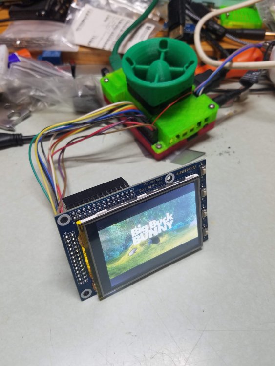
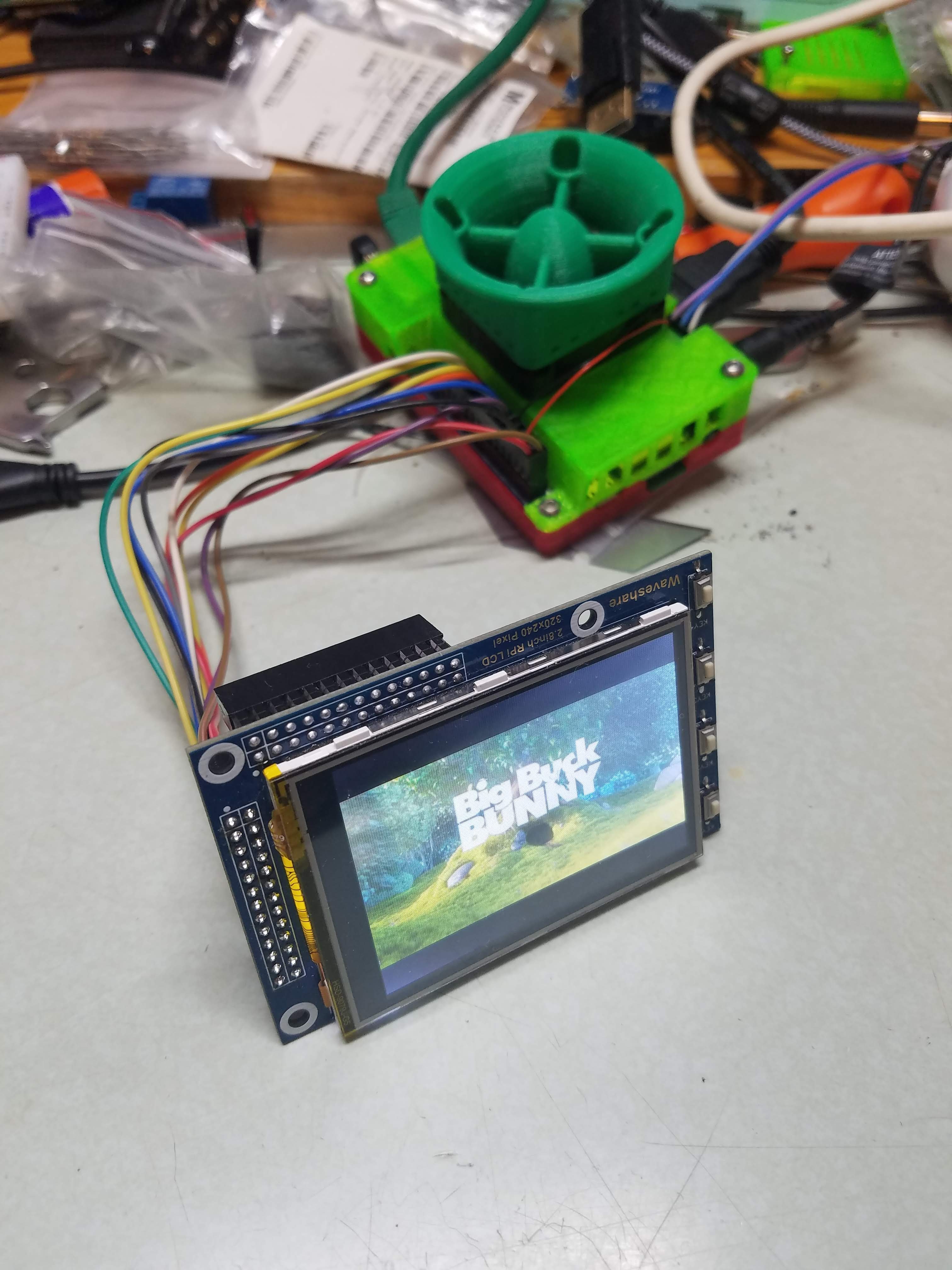
the uboot in that image prevents booting from sd automatically as well, and i didn't find any uboot documentation that made it clear how to manually boot from sd, though i did hook up a serial console. This is what it said. The LED never turned green, the display flashes once but displays no images or text.
QuoteU-Boot TPL 2021.07-armbian (Feb 27 2022 - 08:51:28)
Channel 0: LPDDR4, 50MHz
BW=32 Col=10 Bk=8 CS0 Row=15 CS1 Row=15 CS=2 Die BW=16 Size=2048MB
Channel 1: LPDDR4, 50MHz
BW=32 Col=10 Bk=8 CS0 Row=15 CS1 Row=15 CS=2 Die BW=16 Size=2048MB
256Bstride
lpddr4_set_rate: change freq to 400000000 mhz 0, 1
lpddr4_set_rate: change freq to 800000000 mhz 1, 0
Trying to boot from BOOTROM
Returning to boot ROM...
U-Boot SPL 2021.07-armbian (Feb 27 2022 - 08:51:28 +0000)
Trying to boot from MMC1
NOTICE: BL31: v2.5(release):c1588782-dirty
NOTICE: BL31: Built : 08:51:19, Feb 27 2022
U-Boot 2021.07-armbian (Feb 27 2022 - 08:51:28 +0000)
SoC: Rockchip rk3399
Reset cause: POR
Model: Pine64 Pinebook Pro
DRAM: 3.9 GiB
PMIC: RK808
MMC: mmc@fe310000: 2, mmc@fe320000: 1, sdhci@fe330000: 0
Loading Environment from SPIFlash... SF: Detected gd25q128 with page size 256 Bytes, erase size 4 KiB, total 16 MiB
*** Warning - bad CRC, using default environment
In: serial
Out: serial
Err: serial
Model: Pine64 Pinebook Pro
Net: No ethernet found.
starting USB...
Bus usb@fe380000: USB EHCI 1.00
Bus usb@fe3a0000: USB OHCI 1.0
Bus usb@fe3c0000: USB EHCI 1.00
Bus usb@fe3e0000: USB OHCI 1.0
Bus dwc3: usb maximum-speed not found
Register 2000140 NbrPorts 2
Starting the controller
USB XHCI 1.10
Bus dwc3: usb maximum-speed not found
Register 2000140 NbrPorts 2
Starting the controller
USB XHCI 1.10
scanning bus usb@fe380000 for devices... 1 USB Device(s) found
scanning bus usb@fe3a0000 for devices... 2 USB Device(s) found
scanning bus usb@fe3c0000 for devices... 3 USB Device(s) found
scanning bus usb@fe3e0000 for devices... 1 USB Device(s) found
scanning bus dwc3 for devices... 1 USB Device(s) found
scanning bus dwc3 for devices... 1 USB Device(s) found
scanning usb for storage devices... 0 Storage Device(s) found
Hit any key to stop autoboot: 0
Device 0: unknown device
Card did not respond to voltage select! : -110
switch to partitions #0, OK
mmc0(part 0) is current device
Scanning mmc 0:1...
Found U-Boot script /boot/boot.scr
3185 bytes read in 20 ms (155.3 KiB/s)
## Executing script at 00500000
Boot script loaded from mmc 0
157 bytes read in 15 ms (9.8 KiB/s)
14235892 bytes read in 637 ms (21.3 MiB/s)
30083584 bytes read in 1311 ms (21.9 MiB/s)
82621 bytes read in 38 ms (2.1 MiB/s)
2698 bytes read in 32 ms (82 KiB/s)
Applying kernel provided DT fixup script (rockchip-fixup.scr)
## Executing script at 09000000
Moving Image from 0x2080000 to 0x2200000, end=3f50000
## Loading init Ramdisk from Legacy Image at 06000000 ...
Image Name: uInitrd
Image Type: AArch64 Linux RAMDisk Image (gzip compressed)
Data Size: 14235828 Bytes = 13.6 MiB
Load Address: 00000000
Entry Point: 00000000
Verifying Checksum ... OK
## Flattened Device Tree blob at 01f00000
Booting using the fdt blob at 0x1f00000 -
17 minutes ago, joey99 said:
Ya, I though it would not be as simple. Shame there isn't as big as a community for the rock64 compared to Raspberry or even the Orange pi, especially on emulation. It's a pretty solid board for that.
The issue is to connect the Rock64 to the display using the provided HDMI angle adapter, I'll have to connect it to the GPIO too. Which is still uncertain as the GPIO's on the Rock64 are slightly different than on the raspberry pi, as what Tony stated. Not sure if it would cause any damage to either the board, screen or both. I could also just use an HDMI cable, but I want to be able to mount the Rock64 on the back of the display with the provided display housing, while also using the provided HDMI angle adapter as it is much neater/cleaner looking.
Unless of course if I use the provided HDMI adapter while it is connected to the GPIO, the pins will be bypassed except the 5v and ground. Otherwise, I'll keep looking around for a display without a GPIO connector.
That screen probably connects the touch panel through GPIO which is not near as big of a deal as getting the whole screen working through the gpio header. If you don't want the touch function, you can ignore it.
It looks like the only way to push video to that screen is hdmi. Which should be fine.
As for whether the connectors will line up? The Rock64 has the same footprint as the raspberry pi 3 and the connectors appear to be in the same places? I'd rate it a solid "maybe".
https://files.pine64.org/doc/rock64/rock64 board dimension.pdf
https://www.mouser.com/new/dfrobot/dfrobot-raspberry-pi-3-bplus/
-
You can get the spi displays to work, but it's not going to be as easy as it is on a raspberry pi.
There are a bunch of old howtos for waveshare screens on orange pi boards and if you use a 4.x.y kernel they will still work but you will have to figure out the gpio numbers for the exact board you are using.
If you want to use a kernel later than 5.17 or something you have to build a dtoverlay, which is a bit on the arcane side.
-
On 8/29/2020 at 10:55 AM, ldiaz said:
Sorry to hear that. The problem you are describing is hard to debug as is related with intermittent communication. It can be anything form octoprint to usb kernel drivers for this SOC, usb cable or sockets or even the firmware of the 3d printer. I think you can enable the serial logger in octoprint to try to identify when the freeze happens.
My experience with a couple of OpiZeros LTS is good with a couple of printers (Ender 3 and a I3 clone) is stable. I've printed long prints of 10-12 h without problems.
When i first started using octoprint on an allwinner board, nanopi m1 in this case, I had a lot of usb connectivity issues with both my printer and a usb camera installed. I eventually found a post somewhere suggesting that the issue was with the "ondemand" cpufreq governor, and that switching the governor to "userspace" or "performance" should fix it, and it did fix it for me. This was on a 4.17 kernel i think. I don't know if the same issue is expected to exist in later kernels.
-
4 hours ago, JORGETECH said:
After some tinkering I disabled the "spi-add-cs1" and "spi-spidev" overlays since they were conflicting with the touchscreen overlay. That still did not fix the problem unfortunately.
Here are the relevant outputs of dmesg:
- dmesg | grep tft
[ 8.850107] fbtft: module is from the staging directory, the quality is unknown, you have been warned.
- dmesg | grep spi
[    8.739055] ads7846: probe of spi1.1 failed with error -22
[    8.759803] [drm] Initialized ili9486 1.0.0 20200118 for spi1.0 on minor 2
[    8.762151] ili9486 spi1.0: [drm] fb1: ili9486drmfb frame buffer device
So the touchscreen could have an initialization error, but I'm not too worried about that right now. The odd thing is that the DRM subsystem seems to correctly identify the TFT framebuffer device, but when I try to use it with apps like "fbi" and "con2fbmap" I still get a white screen.
Clearly getting closer. But i gotta point out, there is more information to be seen on the serial console. usb-to-ttl-serial dongles are cheap and plentiful.
Regretfully it has been several months since i worked on this sort of thing and my memory is foggy. -
7 hours ago, JORGETECH said:
Ok, I fixed the compilation problem by adding "/plugin/;" under "/dts-v1/;". But the screen is still white, maybe my screen has different pinout?
Do you have a serial console? that is the best way to see what is happening during bootup. At first glance i think some detail may be missing from your dts but right now i don't remember enough of my own troubleshooting process. I will look into it again a little later today though.
Double check the pinout - you didn't mention what board you are on and not all h3 headers are alike.
Also i notice that the raspberry pi overlays for the 3.5 screens, of which there are 3 versions, have an "init" stanza that you might need to copy/paste all or part of.
-
I am very confused.
Did you run "sudo apt --add-architecture armhf" and not just "apt --add-architecture"?
Also it's libc6 not livc6.
try "sudo apt-get install libhybris:armhf"
I don't have the specific experience with libhybris but i do have multiarch working on my H5
-
I have the waveshare 2.8 A tft and touch panel working on the Orange Pi PC2 with one long dtoverlay.
Some of my inspiration came from here:
Like i said one dtoverlay, both fbtft and the touch panel, no other overlays needed.
I admit i am a neophyte and it might be possible to trim this one slightly and use it in combination with the CS1 dtoverlay but it wasn't clear to me how that would work.
I am using a 6 inch hand-made cable to connect my waveshare 2.8 A but it is wired straight through on only the needed wires for touch and tft.
As I've said before it should work just the same with a 3.2 B.
May work on PC Prime as-is, should work on other orange pi boards with minor changes (compatible arch and the assignment of pin 26 varies from board to board).
For orange pi zero, zero plus (H3 and H5), maybe some others, instances of PA21 should be changed to PA10. Check your pinouts to be sure.
The spi speed of 1.6mhz for the tft is a safe example, I have run up to 4mhz without issues and might be able to go higher but i am leaving the safe default in place for this post.
one caveat: as i said i don't have a use for the touch panel in my application. I tested it by catting /dev/input/mouse1 and running a fingernail over the touch panel. I got output. yay. More tweaks might be needed, but the driver is fundamentally working and all the overrides are included in the dts
-
5 hours ago, martinayotte said:
Most probably "active_high" vs "active_low" ...
my guess as well
-
I don't have specific experience with widevine but debian-derived distributions including armbian are capable of hosting multiple ABIs.
Your s912 is aarm64 but is backward compatible with armhf. Your 32-bit arm binary is armhf. Similar to how an amd64 system is backward compatible with an i386 system.You start with dpkg --add-architecture armhf
then apt-get update
Then you install 32-bit versions of everything you need for your 32-bit netflix, etc with "apt-get install foo:armhf" and so on.
I've only done this on a small scale, but if you get lucky and everything you need is in the distribution, it's pretty painless. the "ldd" command will tell you what libraries a dynamically linked binary needs to have around.
more info here: https://wiki.debian.org/Multiarch/HOWTO
-
Got it. TFT at least. reset_gpios needed to be 0 0 1 instead of 0 0 0. Yes i should really find where the referece is for what the syntax means instead of trying to intuit it.
I'll see if i can tease the touch into working though i don't really need it for my application. Edit: probably gonna start with copypasta from this but with the correct gpio pins: https://github.com/armbian/sunxi-DT-overlays/blob/master/examples/spi-ads7846.dts
So far I have only tested this on my orange pi pc2 running 5.4.20
-
22 minutes ago, martinayotte said:
Yes, this is an important error, it mean that some parameters inside overlay are not resolved !
Unfortunately, there is no way to get it more verbose during that boot phase.
But, it is a bit easier to debug using dynamic loading :
mkdir /sys/kernel/config/device-tree/overlays/waveshare
cat waveshare.dtbo > /sys/kernel/config/device-tree/overlays/wave/dtbo
Then, "dmesg" reveal a more verbose "OF: resolver: overlay phandle fixup failed: -22" .
It is probably that the line "interrupt-parent = <&gpio>;" should be "interrupt-parent = <&pio>;" instead ...
Thanks for that. - i was unsure about whether that line needed to change.
It loads now, but the screen is still white, so i guess i have more troubleshooting to do.
The touch device also is not working.
[ 8.040102] ads7846: probe of spi1.1 failed with error -22
[ 8.041249] fbtft: module is from the staging directory, the quality is unknown, you have been warned.
[ 8.060153] fb_ili9340: module is from the staging directory, the quality is unknown, you have been warned.
[ 8.062524] fbtft_of_value: buswidth = 8
[ 8.062534] fbtft_of_value: debug = 0
[ 8.062537] fbtft_of_value: rotate = 90
[ 8.062539] fbtft_of_value: fps = 25
[ 8.062542] fbtft_of_value: txbuflen = 32768
I should clarify, while I'm not a programmer, I have been using linux for roughly as long as it has existed, and in a previous life i worked for a now-long-dead embedded linux vendor in QA. But that was almost 20 years ago and if i knew anything about uboot at the time i have forgotten it. I am also not sure device trees were a thing in 2001.
Maybe i should say, as far as my embedded hacking skills are concerned, I have yet to find if there is anything under the rust.
-
OK, this is probably related:
QuoteApplying user provided DT overlay waveshare_32b_28a_opi.dtbo
failed on fdt_overlay_apply(): FDT_ERR_NOTFOUND
Error applying DT overlays, restoring original DT
Is there a way to get a more informative error message?
-
5 hours ago, martinayotte said:
Did you look more thoroughly in "dmesg", maybe there something else missing ...
Yeah, nothing that looks like it is directly related.
the only mention of spi is where it complains about not being able to create a device for spi flash that might not exist.
During the uboot part of bootup it complains about no boot.env and that might be related. Maybe it's not reading armbianEnv.txt at all? I think i might hook up the serial console so i can log the whole boot process.
-
Ok, thanks.
Where should i look for any output generated by this?
-
I am trying to figure out how to create a dtoverlay to allow my waveshare 2.8a fbtft screen to work.
I understand that i the 5.x.y kernels, a dtoverlay is required.
I'm starting with the waveshare32b.dts for raspberry pi, found here:
https://github.com/swkim01/waveshare-dtoverlaysShould be compatible with the 2.8a per waveshare wiki.
I'm trying to modify it in sort of the same way as was done in this thread, for another display:
The board I'm using for this is an orangepi pc2.
But i don't' actually know what I'm doing. What I've come up with so far is this:
/*
 * Device Tree overlay for waveshare 3.2inch B and 2.8inch A TFT LCD
 *
 */

/dts-v1/;
/plugin/;

/ {
        compatible = "allwinner,sun8i-h3", "allwinner,sun50i-h5";

        fragment@0 {
                target = <&spi1>;
                __overlay__ {
                        status = "okay";

                        spidev@0{
                                status = "disabled";
                        };

                        spidev@1{
                                status = "disabled";
                        };
                };
        };

        fragment@1 {
                target = <&pio>;
                __overlay__ {
                        waveshare32b_pins: waveshare32b_pins {
                                allwinner,pins = "pa1", "pa0", "pa3" ;
                                allwinner,function = "gpio_in";
                        };
                };
        };

        fragment@2 {
                target = <&spi1>;
                __overlay__ {
                        /* needed to avoid dtc warning */
                        #address-cells = <1>;
                        #size-cells = <0>;

                        waveshare32b: waveshare32b@0{
                                compatible = "ilitek,ili9340";
                                reg = <0>;
                                pinctrl-names = "default";
                                pinctrl-0 = <&waveshare32b_pins>;

                                spi-max-frequency = <16000000>;
                                txbuflen = <32768>;
                                rotate = <90>;
                                fps = <25>;
                                bgr = <0>;
                                buswidth = <8>;
                                reset-gpios = <&pio 0 0 0>;
                                dc-gpios = <&pio 0 3 0>;
                                debug = <0>;
                        };

                        waveshare32b_ts: waveshare32b-ts@1 {
                                compatible = "ti,ads7846";
                                reg = <1>;

                                spi-max-frequency = <2000000>;
                                interrupts = <17 2>; /* high-to-low edge triggered */
                                interrupt-parent = <&gpio>;
                                pendown-gpio = <&pio 0 1 0>;
                                ti,x-plate-ohms = /bits/ 16 <60>;
                                ti,pressure-max = /bits/ 16 <255>;
                        };
                };
        };

        __overrides__ {
                speed =         <&waveshare32b>,"spi-max-frequency:0";
                txbuflen =      <&waveshare32b>,"txbuflen:0";
                rotate =        <&waveshare32b>,"rotate:0";
                fps =           <&waveshare32b>,"fps:0";
                bgr =           <&waveshare32b>,"bgr:0";
                debug =         <&waveshare32b>,"debug:0";
                swapxy =        <&waveshare32b_ts>,"ti,swap-xy?";
        };
};
There are no errors from armbian-add-overlay, but when i reboot the screen is not working, fbtft is not loaded, and i see no messages in dmesg that look like they relate to my efforts.
So, any clues? Does anything jump out as being wrong? -
Looking through the git logs i found this commit:
https://git.kernel.org/pub/scm/linux/kernel/git/gregkh/staging.git/commit/drivers/staging/fbtft?h=staging-testing&id=2962db71c7030868b6859d09b2138b55297df95eQuoteCommit c440eee1a7a1 ("Staging: fbtft: Switch to the gpio descriptor interface") removed the gpio code from fbtft_device rendering it useless.
fbtft_device is a module that was used on the Raspberry Pi to dynamically add fbtft devices when the Pi didn't have Device Tree support. Just remove the module since it's the responsibility of Device Tree, ACPI or platform code to add devices.
Which explains why the 5.4.y kernels don't include fbtft_device, and clarifies that the only way to use one of these devices in the 5.4.y kernel is with a dtoverlay.
The reference for that would seem to be here:
https://github.com/notro/fbtft/wiki/FBTFT-RPI-overlays
Naturally, the rpi overlays will have to be, uh, adjusted, to use them on any platform that is not an rpi. I can't claim to have a deep understanding of how the device trees work, i'm just pretty sure that something that specifies a broadcom platform aint gonna work on an allwinner, rockchip, etc.
If i feel a need for masochism i might look into it again. Maybe get some more usd cards so i can keep my working 4.19.y setup static.
-
I don't want to talk about how long i beat my head against this but i have it working so i thought i would share.
First, in the 5.4.y kernels, the fbtft_device module seems to be missing? So i am using 5.90 oragepizero ubuntu bionic next 4.19.57 as my image, kernel is upgraded to 4.19.62-sunxi via regular apt-get upgrade.
I have a genuine waveshare 2.8 A rpi lcd. Waveshare states repeatedly that it is compatible with the 3.2 B rpi lcd except for the screen size and number of buttons, so this should work for the 3.2 B lcd as well.
This blog post was pretty helpful: https://kaspars.net/blog/spi-display-orange-pi-zero
But it leaves out the necessity of enabling the spi bus overlays.
So, using armbian-config, go into system -> hardware -> and enable spi-spidev and (I think?) spi-add-cs1 (as recommended by some other posts i have seen).
Then edit (as root) /boot/armbianEnv.txt and add these lines:
param_spidev_spi_bus=1
param_spidev_spi_cs=1extraargs="fbcon=map:8"
edit /etc/modules-load.d/modules.conf and add these lines:
fbtft
fbtft_devicecreate /etc/modprobe.d/fbtft.conf containing this line:
options fbtft_device rotate=90 name=waveshare32b busnum=1 gpios=dc:3,reset:0 speed=32000000
Here's the kicker though. According to the wiki page for this lcd, the lcd cable select is connected to pin 24 and the touchscreen cs pin is on pin 26
https://www.waveshare.com/wiki/2.8inch_RPi_LCD_(A)
But i only had a white screen until i removed the "CS=1" argument from the options line.
I don't' get it. Maybe this means i can't use the touch screen, but I'm not sure i want it for my application.
But if someone can explain what the logic is there, that would be great.
My plan is to ultimately install retropie on it, and remix the "mini commodore pet" retropie enclosure to fit an opi zero instead of a raspberry pi. I've looked at retrorangepi and they don't really target this kind of configuration so that seems like the way to go.
-
Try changing the cpufreq governor to "userspace" or "performance"
BigTreeTech HDMI 7 no video output
in Orange Pi 5 / 5B
Posted · Edited by ej0rge
What the heck are you talking about? HDMI And DVI are both TMDS, the difference is that HDMI supports both RGB and YUV colorspaces and DVI supports only RGB. I am pretty sure the default on computers is RGB anyway. YUV would be for video players.
Are you trying to say that the display supports only YUV signals?