

TCB13
-
Posts
67 -
Joined
-
Last visited
Content Type
Forums
Store
Crowdfunding
Applications
Events
Raffles
Community Map
Posts posted by TCB13
-
-
Hello,
I had a NanoPi M4v2 running 5.10.63 (buster) for a while without issue. Both I2C and SPI were working perfectly fine and the system was stable. Today apt updated the kernel to 5.15.25 and it broke multiple things, the first issue was that the network wasn't working properly, yellow light but not green one / no IP requested from the local DHCP server.
The overlays on this system were:
overlays=dwc3-0-host i2c7 i2c8 spi-spidev
overlays=dwc3-0-host i2c7 i2c8 spi-spidevI connected the eMMC moule to a card reader and removed the overlays one by one and found out that `i2c8` was breaking my boot / network:
overlays=dwc3-0-host i2c7 spi-spidevAlthough the rest of them weren't breaking anything they didn't work. SPI wasn't showing up under `/dev/spidev1.0` nor the remaining I2C devices.
Important notes:
- Since the board wasn't connected to any network I was unable to create an armbian log or recover any further information;
- There seems to be a related issue with another board: https://forum.armbian.com/topic/20033-51525-breaks-spi-on-nanopi-neo-and-does-not-create-devspidev00
- I tried a fresh image of "bullseye" and got the same issues as soon as I enabled the overlays;
- I ended up downgrading the kernel and everything is working fine now.
-
-
On 1/7/2020 at 8:21 AM, n_b said:
Hi,
Has anyone successfully connected a ds18b20 sensor to Nanopi M4?
I've successfully connected to a raspberry pi B+. There is a lot of guides for the RPi it but none for the M4.
I'm using armbian stretch on the m4.
Thanks,
I was trying to accomplish the same... however after enabling the w1-gpio overlay I get this:
:~# dmesg | grep wire
[    6.696830] Driver for 1-wire Dallas network protocol.
[    6.702902] gpio-36 (onewire@0): enforced open drain please flag it properly in DT/ACPI DSDT/board file
[    6.703002] OF: /onewire@0: could not get #gpio-cells for /vop@ff8f0000/port/endpoint@2
[    6.703013] w1-gpio onewire@0: gpio_request_one (ext_pullup_enable_pin) failed
[    6.703069] w1-gpio: probe of onewire@0 failed with error -22
I also tried to add "param_w1_pin=GPIO1_C7" in order to have it working at physical pin 18 / gpio 55 without luck. Strangely enough I still get the same error about gpio-36 (GPIO1_A4) after adding that line...
~# cat /sys/kernel/debug/gpio
gpiochip0: GPIOs 0-31, parent: platform/pinctrl, gpio0:
 gpio-1   (                    |vcc3v0-sd           ) out hi
 gpio-4   (                    |host-wakeup         ) in  lo
 gpio-5   (                    |GPIO Key Power      ) in  hi ACTIVE LOW
 gpio-7   (                    |cd                  ) in  hi ACTIVE LOW
 gpio-9   (                    |shutdown            ) out hi
 gpio-10  (                    |reset               ) out hi ACTIVE LOW
 gpio-13  (                    |status_led          ) out lo

gpiochip1: GPIOs 32-63, parent: platform/pinctrl, gpio1:

gpiochip2: GPIOs 64-95, parent: platform/pinctrl, gpio2:
 gpio-68  (                    |ep                  ) out hi
 gpio-90  (                    |device-wakeup       ) out lo

gpiochip3: GPIOs 96-127, parent: platform/pinctrl, gpio3:
 gpio-111 (                    |PHY reset           ) out hi ACTIVE LOW

gpiochip4: GPIOs 128-159, parent: platform/pinctrl, gpio4:
I'm currently wiring the sensor to my NanoPi M4v2 with a 4.7k resistor, similar to this:
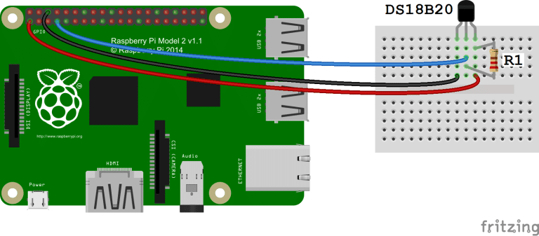
System: 5.10.63-rockchip64 #21.08.2 SMP PREEMPT Wed Sep 8 10:57:23 UTC 2021 aarch64 GNU/Linux
Anyone has tips? Thank you.
-
I finally managed to get this work. Things I was doing wrong:
- Not using the OPi.GPIO replacement library - others aren't compatible with the NanoPi M4;
- DIN LCD pin was connected to the SBC RXD instead of TXD;
- Passed wrong pin numbers to the libraries (should be the real physical pins numers);
- Mistaking SPI port with device...
Here the full guide on how to it properly. Start by installing:
apt-get install python3 python3-pip python3-pil libjpeg-dev zlib1g-dev libfreetype6-dev liblcms2-dev libopenjp2-7 libtiff5 -y
pip3 install luma.oled
apt-get remove python3-rpi.gpio rpi.gpio-common
pip3 install --upgrade OPi.GPIO
Wire up your LCD as:
MISO > GPIO1_B0 > SPI1_TXD > 19    > LCD DIN | Blue
SCK > GPIO1_B1 > SPI1_CLK > 23     > LCD CLK | Yellow
CS > GPIO1_B2  > SPI1_CSn0 > 24    > LCD CS | Orange

RST > GPIO1_A1(3V) > M4 Pin 11     >  LCD RST Pin | White
DC > GPIO1_A3(3V)  > M4 Pin 13     >  LCD DC Pin | Green
Download an run an example:
git clone https://github.com/rm-hull/luma.examples.git

python3 luma.examples/examplebounce.py
--display=ssd1351 \
--interface=spi \
--width=128 --height=128 \
--spi-bus-speed=50000000 \
--spi-device=0 \
--spi-port=1 \
--gpio-reset=11 \
--gpio-data-command=13 \
--gpio OPi.GPIO \
--gpio-mode nanopi.m4.BOARD
And you should get something like this:
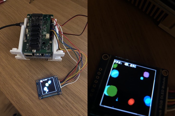
It seems to be able to drive the display up to around 45fps without noises like I've experienced before in an Arduino.
Enjoy.
-
Following my lack of knowledge of the subject I found out another GPIO implementation that seems to have mappings for the NanoPi M4 called OPi.GPIO.
Rewired the LCD, I was unsure about the GPIO pin I picked for the DC pin:
MOSI > GPIO1_A7 > SPI1_RXD > M4 Pin 21   > LCD DIN Pin (blue)
SCK > GPIO1_B1 > SPI1_CLK > M4 Pin 23     > LCD CLK Pin (yellow)
CS > GPIO1_B2  > SPI1_CSn0 > M4 Pin 24    > LCD CS Pin (orange)

RST > GPIO1_A1(3V) > M4 Pin 11    >   LCD RST Pin (white)
DC > GPIO1_A3(3V)  > M4 Pin 13        >   LCD DC Pin (green)
Installed and run the thing without much success:
pip3 install --upgrade OPi.GPIO

ls /dev/spi*
/dev/spidev1.0

python3 luma.examples/examples/3d_box.py  \
--display=ssd1351 \
--interface=spi \
--width=128 --height=128 \
--spi-bus-speed=16000000 \
--bgr \
--spi-device=1 --spi-port=0 \
--gpio-reset=35 \
--gpio-data-command=33 \
--gpio OPi.GPIO \
--gpio-mode nanopi.m4.BOARD

Traceback (most recent call last):
  File "luma.examples/examples/3d_box.py", line 129, in <module>
    device = get_device()
  File "/root/luma.examples/examples/demo_opts.py", line 61, in get_device
    device = cmdline.create_device(args)
  File "/usr/local/lib/python3.7/dist-packages/luma/core/cmdline.py", line 246, in create_device
    device = Device(serial_interface=interface(), **params)
  File "/usr/local/lib/python3.7/dist-packages/luma/core/cmdline.py", line 161, in spi
    gpio=self.gpio or GPIO)
  File "/usr/local/lib/python3.7/dist-packages/luma/core/interface/serial.py", line 299, in __init__
    bitbang.__init__(self, gpio, transfer_size, reset_hold_time, reset_release_time, DC=gpio_DC, RST=gpio_RST)
  File "/usr/local/lib/python3.7/dist-packages/luma/core/interface/serial.py", line 187, in __init__
    self._DC = self._configure(kwargs.get("DC"))
  File "/usr/local/lib/python3.7/dist-packages/luma/core/interface/serial.py", line 200, in _configure
    self._gpio.setup(pin, self._gpio.OUT)
  File "/usr/local/lib/python3.7/dist-packages/OPi/GPIO.py", line 470, in setup
    pin = get_gpio_pin(_mode, channel)
  File "/usr/local/lib/python3.7/dist-packages/OPi/pin_mappings.py", line 80, in get_gpio_pin
    return _pin_map[mode][channel]
KeyError: 33
From what I understand of https://github.com/rm-hull/OPi.GPIO/blob/master/nanopi/m4.py my physical pin 11 maps to GPIO 33 and physical pin 13 to GPIO 35. Is this even correct?
Either way it still fails.
-
Now unfortunately luma-oled seems to be yet another problem. I wired up my LCD as:
MOSI > GPIO1_A7 > SPI1_RXD > M4 Pin 21 > LCD DIN Pin (blue)
SCK > GPIO1_B1 > SPI1_CLK > M4 Pin 23 > LCD CLK Pin (yellow)
CS > GPIO1_B2 > SPI1_CSn0 > M4 Pin 24 > LCD CS Pin (orange)DC > GPIO1_A0(3V) > M4 Pin 7 > LCD DC Pin (green)
RST > GPIO1_A1(3V) > M4 Pin 11 > LCD RST Pin (white)
Display: https://www.ebay.com/itm/203101646517
Datasheet: https://www.waveshare.com/w/upload/5/5b/1.5inch_RGB_OLED_Module_User_Manual_EN.pdf
From my understanding I had to get GPIO1_A0 and GPIO1_A1 in the system so the lib could use them.
According to this https://hev.cc/2927.html GPIO mapping I tried:
ls -la /dev/spi*
crw------- 1 root root 153, 0 Sep 16 18:51 /dev/spidev1.0

echo 32 > /sys/class/gpio/export
echo 33 > /sys/class/gpio/export

ls -la /sys/class/gpio/
total 0
drwxr-xr-x  2 root root       0 Jan 18  2013 .
drwxr-xr-x 76 root root       0 Jan 18  2013 ..
--w--w----  1 root dialout 4096 Sep 16 20:51 export
lrwxrwxrwx  1 root root       0 Sep 16 20:50 gpio32 -> ../../devices/platform/pinctrl/gpiochip1/gpio/gpio32
lrwxrwxrwx  1 root root       0 Sep 16 20:50 gpio33 -> ../../devices/platform/pinctrl/gpiochip1/gpio/gpio33
lrwxrwxrwx  1 root root       0 Jan 18  2013 gpiochip0 -> ../../devices/platform/pinctrl/gpio/gpiochip0
lrwxrwxrwx  1 root root       0 Jan 18  2013 gpiochip128 -> ../../devices/platform/pinctrl/gpio/gpiochip128
lrwxrwxrwx  1 root root       0 Jan 18  2013 gpiochip32 -> ../../devices/platform/pinctrl/gpio/gpiochip32
lrwxrwxrwx  1 root root       0 Jan 18  2013 gpiochip64 -> ../../devices/platform/pinctrl/gpio/gpiochip64
lrwxrwxrwx  1 root root       0 Jan 18  2013 gpiochip96 -> ../../devices/platform/pinctrl/gpio/gpiochip96
--w--w----  1 root dialout 4096 Sep 16 19:19 unexport
Now I tried the luma-oled examples (running as root):
python3 3d_box.py --display ssd1351 --interface spi --spi-port 0 --spi-device 1 --gpio-reset 33 --gpio-data-command 32 --width 128 --height 128
usage: 3d_box.py >(....)
3d_box.py: error: GPIO access not available
I'm not even sure if this part "--gpio-reset 33 --gpio-data-command 32" is correct. I've tried both the virtual pin number and the hardware number without luck.
Also tried to install https://github.com/friendlyarm/RPi.GPIO_NP without much luck:
apt-get update
apt-get install python-dev
git clone https://github.com/friendlyarm/RPi.GPIO_NP
cd RPi.GPIO_NP
python3 setup.py install
python3 setup.py install

python3 luma.examples/examples/3d_box.py --display=ssd1351 --interface=spi --width=128 --height=128 --spi-bus-speed=16000000 --bgr --spi-device=1 --spi-port=0 --gpio-reset=33 --gpio-data-command=32 --gpio RPi.GPIO

Traceback (most recent call last):
(...)
RuntimeError: It is not NanoPi based board.
-
On 6/6/2021 at 9:21 AM, piter75 said:
@TCB13 I am a bit late to the party but I figured it may still be needed ;-)
spi-spidev is a special / dynamic overlay. Besides enabling it you need to also configure it and armbian-config cannot currently do that.
For configuration options have a look here:
You can also consult the local README file located in: /boot/dtb/rockchip/overlay/README.rockchip-overlays
Your comment was crucial to fix my "issue". I enabled the overlay and then as described on the file edited `/boot/armbianEnv.txt` in order to include:
param_spidev_spi_bus=1
param_spidev_max_freq=100000000
Now the SPI shows up:
~# ls -la /dev/spi*
crw------- 1 root root 153, 0 Sep 16 18:51 /dev/spidev1.0
Also passes the spidev_test (https://raw.githubusercontent.com/torvalds/linux/master/tools/spi/spidev_test.c)
~# ./spidev_test
spi mode: 0x0
bits per word: 8
max speed: 500000 Hz (500 kHz)
(Had to adjust the path)
Thank you for the tip!
-
I've been using the following table with the M4v2:
------+-----+----------+------+ Model  NanoPi-M4 +------+----------+-----+------+
 | GPIO | wPi |   Name   | Mode | V | Physical | V | Mode |   Name   | wPi | GPIO |
 +------+-----+----------+------+---+----++----+---+------+----------+-----+------+
 |      |     |     3.3V |      |   |  1 || 2  |   |      | 5V       |     |      |
 |      |     | I2C2_SDA |      |   |  3 || 4  |   |      | 5V       |     |      |
 |      |     | I2C2_SCL |      |   |  5 || 6  |   |      | GND(0V)  |     |      |
 |   32 |   7 | GPIO1_A0 |  OUT | 0 |  7 || 8  |   | ALT  | GPIO4_C1 | 15  |  145 |
 |      |     |  GND(0V) |      |   |  9 || 10 |   | ALT  | GPIO4_C0 | 16  |  144 |
 |   33 |   0 | GPIO1_A1 |   IN | 0 | 11 || 12 | 1 | IN   | GPIO1_C2 | 1   |  50  |
 |   35 |   2 | GPIO1_A3 |   IN | 0 | 13 || 14 |   |      | GND(0V)  |     |      |
 |   36 |   3 | GPIO1_A4 |   IN | 0 | 15 || 16 | 0 | IN   | GPIO1_C6 | 4   |  54  |
 |      |     |     3.3V |      |   | 17 || 18 | 0 | IN   | GPIO1_C7 | 5   |  55  |
 |      |     | UART4_TX |      |   | 19 || 20 |   |      | GND(0V)  |     |      |
 |      |     | UART4_RX |      |   | 21 || 22 | 0 | IN   | GPIO1_D0 | 6   |  56  |
 |      |     | SPI1_CLK |      |   | 23 || 24 |   |      | SPI1_CSn |     |      |
 |      |     |  GND(0V) |      |   | 25 || 26 |   | ALT  | GPIO4_C5 | 11  |  149 |
 |      |     | I2C2_SDA |      |   | 27 || 28 |   |      | I2C2_SCL |     |      |
 |      |     | I2S0_LRX |      |   | 29 || 30 |   |      | GND(0V)  |     |      |
 |      |     | I2S0_LTX |      |   | 31 || 32 |   |      | I2S_CLK  |     |      |
 |      |     | I2S0_SCL |      |   | 33 || 34 |   |      | GND(0V)  |     |      |
 |      |     | I2S0SDI0 |      |   | 35 || 36 |   |      | I2S0SDO0 |     |      |
 |      |     | I2S0I1O3 |      |   | 37 || 38 |   |      | I2S0I2O2 |     |      |
 |      |     |  GND(0V) |      |   | 39 || 40 |   |      | I2S0I3O1 |     |      |
 +------+-----+----------+------+---+----++----+---+------+----------+-----+------+
Let's try GPIO1_A4:
echo 36 > /sys/class/gpio/export
echo "out" >/sys/class/gpio/gpio36/direction
echo "1" > /sys/class/gpio/gpio36/value
And then I can measure 3v with a multimeter hooked to the physical pin 15.
-
Now unfortunately luma-oled seems to be yet another problem. I wired up my LCD as:
MOSI > GPIO1_A7 > SPI1_RXD > M4 Pin 21 > LCD DIN Pin (blue)
SCK > GPIO1_B1 > SPI1_CLK > M4 Pin 23 > LCD CLK Pin (yellow)
CS > GPIO1_B2 > SPI1_CSn0 > M4 Pin 24 > LCD CS Pin (orange)DC > GPIO1_A0(3V) > M4 Pin 7 > LCD DC Pin (green)
RST > GPIO1_A1(3V) > M4 Pin 11 > LCD RST Pin (white)
From my understanding I had to get GPIO1_A0 and GPIO1_A1 in the system so the lib could use them.
According to this https://hev.cc/2927.html GPIO mapping I tried:
ls -la /dev/spi*
crw------- 1 root root 153, 0 Sep 16 18:51 /dev/spidev1.0

echo 32 > /sys/class/gpio/export
echo 33 > /sys/class/gpio/export

ls -la /sys/class/gpio/
total 0
drwxr-xr-x  2 root root       0 Jan 18  2013 .
drwxr-xr-x 76 root root       0 Jan 18  2013 ..
--w--w----  1 root dialout 4096 Sep 16 20:51 export
lrwxrwxrwx  1 root root       0 Sep 16 20:50 gpio32 -> ../../devices/platform/pinctrl/gpiochip1/gpio/gpio32
lrwxrwxrwx  1 root root       0 Sep 16 20:50 gpio33 -> ../../devices/platform/pinctrl/gpiochip1/gpio/gpio33
lrwxrwxrwx  1 root root       0 Jan 18  2013 gpiochip0 -> ../../devices/platform/pinctrl/gpio/gpiochip0
lrwxrwxrwx  1 root root       0 Jan 18  2013 gpiochip128 -> ../../devices/platform/pinctrl/gpio/gpiochip128
lrwxrwxrwx  1 root root       0 Jan 18  2013 gpiochip32 -> ../../devices/platform/pinctrl/gpio/gpiochip32
lrwxrwxrwx  1 root root       0 Jan 18  2013 gpiochip64 -> ../../devices/platform/pinctrl/gpio/gpiochip64
lrwxrwxrwx  1 root root       0 Jan 18  2013 gpiochip96 -> ../../devices/platform/pinctrl/gpio/gpiochip96
--w--w----  1 root dialout 4096 Sep 16 19:19 unexport
Now I tried the luma-oled examples (running as root):
python3 3d_box.py --display ssd1351 --interface spi --spi-port 0 --spi-device 1 --gpio-reset 33 --gpio-data-command 32 --width 128 --height 128
usage: 3d_box.py >(....)
3d_box.py: error: GPIO access not available
I'm not even sure if this part "--gpio-reset 33 --gpio-data-command 32" is correct. I've tried both the virtual pin number and the hardware number without luck.
Also tried to install https://github.com/friendlyarm/RPi.GPIO_NP without much luck:
apt-get update apt-get install python-dev git clone https://github.com/friendlyarm/RPi.GPIO_NP cd RPi.GPIO_NP python3 setup.py install python3 setup.py install python3 luma.examples/examples/3d_box.py --display=ssd1351 --interface=spi --width=128 --height=128 --spi-bus-speed=16000000 --bgr --spi-device=1 --spi-port=0 --gpio-reset=33 --gpio-data-command=32 --gpio RPi.GPIO Traceback (most recent call last): (...) RuntimeError: It is not NanoPi based board. -
On 6/6/2021 at 9:21 AM, piter75 said:
@TCB13 I am a bit late to the party but I figured it may still be needed ;-)
spi-spidev is a special / dynamic overlay. Besides enabling it you need to also configure it and armbian-config cannot currently do that.
For configuration options have a look here:
You can also consult the local README file located in: /boot/dtb/rockchip/overlay/README.rockchip-overlays
Your comment was crucial to fix my "issue". I enabled the overlay and then as described on the file edited `/boot/armbianEnv.txt` in order to include:
param_spidev_spi_bus=1
param_spidev_max_freq=100000000
Now the SPI shows up:
~# ls -la /dev/spi*
crw------- 1 root root 153, 0 Sep 16 18:51 /dev/spidev1.0
Also passes the spidev_test (https://raw.githubusercontent.com/torvalds/linux/master/tools/spi/spidev_test.c)
~# ./spidev_test
spi mode: 0x0
bits per word: 8
max speed: 500000 Hz (500 kHz)
(Had to adjust the path)
Thank you for the tip!
-
2 hours ago, piter75 said:
@TCB13 I am a bit late to the party but I figured it may still be needed ;-)
spi-spidev is a special / dynamic overlay. Besides enabling it you need to also configure it and armbian-config cannot currently do that.
For configuration options have a look here:
You can also consult the local README file located in: /boot/dtb/rockchip/overlay/README.rockchip-overlays
Never late to the party! Thank you for your tips.
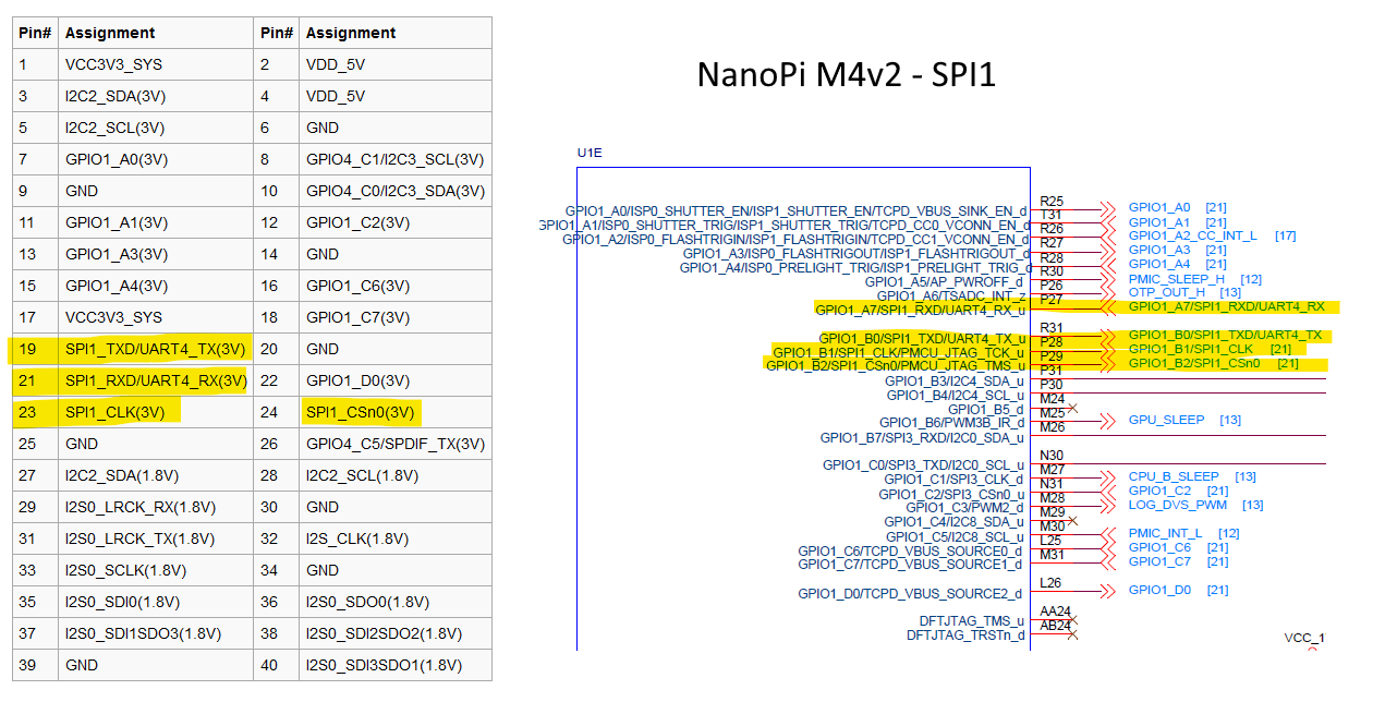
Btw, for future reference fro anyone going about the same path, page 11 of the NanoPi M4v2 schematic contains a definition of the SPI1 that can be easily between the overlay and physical pins.
Schematic: http://wiki.friendlyarm.com/wiki/images/c/cc/NanoPi-M4V2_1908_Schematic.pdf
Physical pin assignment: https://wiki.friendlyarm.com/wiki/index.php/NanoPi_M4V2#Diagram.2C_Layout_and_Dimension

-
2 hours ago, Igor said:
FYI. A few days of debugging costs few thousand eur. We have 0 eur budget per year for that. Patiently waiting for donation that will cover the time dealing with this problem so we can hire someone to fix this for you.
If this is not life and death, this will not be a problem.
I can afford only a few minutes per bug or per "client". Usually less then 1m. For debugging help - my first available pro bono days are not this year ...
Wrote on mobile
I think there is a misunderstanding here, I never requested support in "record time" and I certainly didn't said that it needs to happen fast. I just said I would upload my log file as soon as I can.
I'm happy with the "few minutes" whenever you guys have some spare time!
-
46 minutes ago, Igor said:
If a few days will be needed to solve this problem, what you will do?
I'll wait patiently for some news. It's not a life or death situation
")
-
1 minute ago, Werner said:

Okay, you win
 I'll provide the file ASAP.
-
I'm sorry but...
- it is for an unsupported board or image (CSC/EOS/WIP/edge) > It's a supported board
- it is for software that is not supported (such as userspace modules installed on top of the core operating system) > NO
- it has been logged in the wrong forum (for example requests for help that are not actual bug reports) > NO, its a bug.
- it lacks requested data (armbianmonitor output) > Not relevant in this case.
- it could have been easily solved by a quick search and/or reading documentation > ??
-
Hello,
I'm trying to use the NanoPi M4v2 SPI however it doesn't seem to work. I used armbian-config to enable the gpio overlay:
[ ] dwc3-0-host
[ ] i2c7
[ ] i2c8
[*] pcie-gen2
[ ] rk3328-opp-1.4ghz
[ ] rk3328-opp-1.5ghz
[ ] rk3399-opp-2ghz
[ ] spi-jedec-nor
[*] spi-spidev
[ ] uart4
[ ] w1-gpio
And the SPI isn't showing up on /dev:
ls /dev/spi*
ls: cannot access '/dev/spi*': No such file or directory
Wasn't this enough to be able to use the SPI1 on this board?
SBC: NanoPi M4V2
System: 5.10.35-rockchip64 #21.05.1 SMP PREEMPT Fri May 7 13:53:11 UTC 2021 aarch64 GNU/Linux
Thank you.
-
7 hours ago, tparys said:
So the M4V2 is a supported board. that the SPI isn't working is probably worth a post by itself in the Rockchip 3399 Subforum.
At a glance, I tried turning on the SPI on my M4V2 and didn't see any spidev devices pop up, but might need to pull out the serial console to see if u-boot is throwing any warnings about the overlay.
Taking a look at the overlay, I'm not sure it looks correct, as it looks like even if it applies the SPI channel is disabled.
        fragment@4 {
                target = <0xffffffff>;

                __overlay__ {
                        #address-cells = <0x01>;
                        #size-cells = <0x00>;

                        spidev {
                                compatible = "spidev";
                                status = "disabled";
                                reg = <0x00>;
                                spi-max-frequency = <0x989680>;
                        };
                };
        };
Thank you for your feedback!
-
Hello,
I'm trying to find out how to use a 1.5 Inch RGB OLED Display that uses the SSD1351 IC on a NanoPi M4 however I don't seem to be able to turn on the SPI.
I used armbian-config to enable the gpio overlay:
[ ] dwc3-0-host
[ ] i2c7
[ ] i2c8
[*] pcie-gen2
[ ] rk3328-opp-1.4ghz
[ ] rk3328-opp-1.5ghz
[ ] rk3399-opp-2ghz
[ ] spi-jedec-nor
[*] spi-spidev
[ ] uart4
[ ] w1-gpio
And the SPI isn't showing up on /dev:
ls /dev/spi*
ls: cannot access '/dev/spi*': No such file or directory
Wasn't this enough to be able to use the SPI1 on this board?
SBC: NanoPi M4V2
System: 5.10.35-rockchip64 #21.05.1 SMP PREEMPT Fri May 7 13:53:11 UTC 2021 aarch64 GNU/Linux
Display: https://www.ebay.com/itm/203101646517
Datasheet: https://www.waveshare.com/w/upload/5/5b/1.5inch_RGB_OLED_Module_User_Manual_EN.pdf
Thank you.
-
6 hours ago, tony013 said:
I have a rockpi - normal size - and a rk3399 device too. So I think, both have more in common, than they differ.
Indeed they've more in common than they differ.
-
2 hours ago, tony013 said:
Well - not similar from assembly, but similar in use case
I have Sata Tower from radxa. I have 4 ssd attached, but I didn't run any benchmarks. I love the small form factor, and its going to be useful after I ported driver from radxa.
Are you going to use it with the NanoPI?
-
3 hours ago, tparys said:
But before you reinvent the wheel, have you considered that you basically made a Helios64 without the nice enclosure?
Yes I did, however the limitation on the number of bays x price didn't make me very happy. My current setup with more SATA expansion boards can go up to 20 bays without cascading and 75 with cascading.
And.. I already had a M4v2 with a the NVMe adapter so... No more costs there.
-
Here, my testing setup with both boards. Everything powered up by a standard ATX power supply.
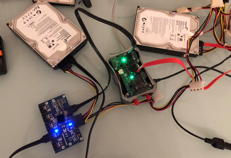
Now I did run some benchmarks on the disks.
System/Kernel: Armbian 21.05.1 Buster with Linux 5.10.35-rockchip64
Hard Drives: Seagate Barracuda 7200rpm 1TB. ST31000524AS (hard drives from 06/2012)https://www.seagate.com/docs/pdf/en-GB/datasheet/disc/barracuda-7200-12-ds1668-6-1101gb.pdf

Scenario: Amrbian installed to the SATA hard drive using the armbian-config helper tool. BTRFS filesystem used.
Benchmark Command: dd if=/dev/zero of=test bs=100MB count=100 conv=fdatasync
Notes: I enabled the PCIe x2 overlay.
- HDD Attached to the SATA to M2 Board (HDD > SATA to M2 > NanoPI M4v2)
10000000000 bytes (10 GB, 9.3 GiB) copied, 27.248 s, 367 MB/s
10000000000 bytes (10 GB, 9.3 GiB) copied, 24.6339 s, 406 MB/s
- HDD Attached to the SATA Expansion Board (HDD > SATA Expansion Board > SATA to M2 > NanoPI M4v2)
10000000000 bytes (10 GB, 9.3 GiB) copied, 25.1813 s, 397 MB/sConclusion: I run the test multiple times I was getting around 350-400MB/s regardless of having the disk connected to the SATA Expansion board or to the SATA to M2 board directly.
I run the same test by while booting from an eMMC card. The performance is the same if the the disks are mounted with:
mount -t btrfs -o defaults,noatime,commit=600,compress=lzo,x-gvfs-hide /dev/sda1 /mnt/HDD
Interestingly the performance of ext4 was very bad (tested both as boot device and simple mount):
Quote10000000000 bytes (10 GB, 9.3 GiB) copied, 79.0775 s, 126 MB/s
So it seems I'm able to build a low power and high capacity NAS with this setup. Please note that I'm not after the best performance and parallel wiring to disks. I also seem to be able to write simultaneously to two disks without a performance drop and that's enough for my use case.
Does anyone has a similar setup?
-
So, after some research I decided to tune down a bit my project. I decided to ditch the NVMe as boot device because I believe a regular SATA SSD will be enough for my use case.
My goal was:
- Boot from a SATA SSD;
- Have around 10 SATA ports for 3.5" hard drives.
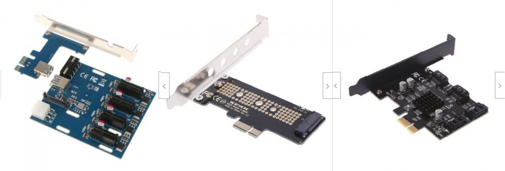
I ended up buying the following:
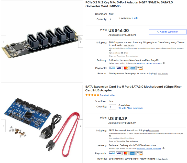
I chose this PCIe to SATA because I already had the NVMe adapter for my M4v2 and it uses the JMB585 chip is used by other SBC manufacturers in hats thus compatible with Armbian. This chip also features "Cascaded mode: support up to x75 SATA devices with JMB575" that allows me to pair it with the other board (based on JMB575) to have more SATA ports.
-
Hello,
I've been using a M4V2 since its release mostly as a NAS (disks over UBS 3.0). I also have it booting from a Samsung NVMe with the official NVMe hat. My setup works flawlessly however I was thinking about ways to add more storage with reasonable performance/price so I thought, what if I managed to add a standard PCIe x1 port from the pins on the board and use standard hardware with it.
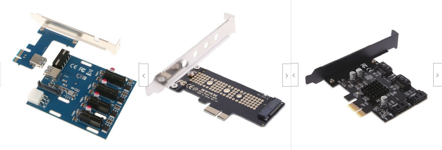
The idea was to add a cheap PCI switch + NVMe adapter (to boot from) and a PCI to SATA controller such as the following:
1) PCI Switch: https://www.ebay.com/itm/PCI-Express-1X-to-4X-PCI-E-4-Ports-Switch-Multiplier-Expansion-Riser-Card-New/293564888755
2) PCI > NVMe Adapter: https://www.ebay.com/itm/NVMe-PCIe-x4-x2-M-2-NGFF-SSD-to-PCIe-x1-converter-card-adapter-PCIe-x1-to-M-00e/143915406968
3) PCI > Sata: https://www.ebay.com/itm/PCI-Express-1x-To-4-Port-Sata-3-0-6G-Expansion-Controller-Card-Marvell-88SE9215/233219670613
Did anyone had success with a setup like this? It looks like there isn't any adapter for the board to add a standard PCI interface, however I could probably solder something. Software wise would it work? I believe the Marvell 88SE9215 is supported by Armbian from what I read on espressobin threads. Any tips?
Thank you!
5.15.25 breaks SPI on NanoPi Neo and does not create /dev/spidev0.0
in Allwinner sunxi
Posted
Seems like I'm having the same issue with a NanoPi M4v2
but unfortunately in my case it breaks the system even more.