

mboehmer
-
Posts
142 -
Joined
-
Last visited
Content Type
Forums
Store
Crowdfunding
Applications
Events
Raffles
Community Map
Everything posted by mboehmer
-
Did I tell you already that the build system is really a miracle? Will try, had problems building Jessie today, apparently packages couldn't be downloaded. Starting new attempt right now.
-
Indeed. Seems to be bank AO related (while that could also be somehow quirky in 5.77, as switching off failed there, too, but that's just my feeling). Is there any way to force the Armbian build system to use an older version? I had 5.77 running at least, so while you look at it (much appreciated!) I could continue with the GPIO stuff.
-
Another observation, which indicates that the AO bank may have problems: one pin AO_BIT2 is used to control the main DC/DC regulator (VCCK), and switching off the Odroid C2 leads to a reboot instead of shutdown. So my best guess is that something in bank AO goes wrong, and both effects have the same root.
-
Found something strange in both bionic and jessie dmesg output: [ 1.677916] GPIO line 501 (usb-hub-reset) hogged as output/high [ 1.684494] gxbb-aoclkc c8100000.sys-ctrl:clock-controller: Clock registration failed [ 1.684533] gxbb-aoclkc: probe of c8100000.sys-ctrl:clock-controller failed with error -17 [ 1.685152] soc soc0: Amlogic Meson GXBB (S905) Revision 1f:c (0:1) Detected [ 1.687516] Serial: 8250/16550 driver, 4 ports, IRQ sharing enabled According to C2 schematics, UART_AO_A is on AO bank. Maybe we should check on that part? Edit: seems to be located in drivers/clk/meson/meson-aoclk.c, according to the error message meson_aoclkc_probe() failed. Edit: I'm lost in tracing back the error number. Could be KDB_BADREG. Seems to happen in clk_hw_register() or clk_create_clk().
-
Sir, yes, sir! Edit: I use "stretch", not "jessie". Welcome to ARMBIAN 5.78 user-built Debian GNU/Linux 9 (stretch) 4.19.34-meson64 System load: 0.67 0.28 0.10 Up time: 1 min Memory usage: 4 % of 1976MB IP: 10.162.208.175 CPU temp: 33°C Usage of /: 8% of 15G Edit: bionic compiled. Same result, no console. Welcome to ARMBIAN 5.78 user-built Ubuntu 18.04.2 LTS 4.19.34-meson64 System load: 0.46 0.11 0.04 Up time: 0 min Memory usage: 4 % of 1976MB IP: 10.162.208.175 CPU temp: 27°C Usage of /: 6% of 15G
-
I have no /dev/ttyAML0 and /dev/ttyAML1 on my Odroid C2.
-
-
Sorry, double post. should pick coffee first
-
I use only eMMC card, no SD cards. I tried with two images, and yes, I use etcher (on Windows, sorry, it's my main machine here). Even tried a different USB serial converter, and checked output of console header with scope. No edges after "starting kernel..." Just for understanding: /dev/tty1 should be routed to the J2 Rxd/TxD pins, so "echo BLA > /dev/tty1" should give some edges on J2 UART?
-
A lot to learn I have. More complex simple things are. Will try tomorrow morning! EDIT: confirmed working! Thanks
-
I tried "verbosity=2". With that I don't see any further messagew after "starting kernel...".
-
Hi, I compiled some images for C2 yesterday (mainline 5.77, jessie), and had a nice console as usual. Today, the new images still have u-boot console, and give some information about kernel starting, but no login by console (USB serial) is possible. I tried to set "console=serial" in /boot/armbianEnv.txt, but that gives me an endless reboot loop. Were there some changes? Maybe in baudrate? I get u-boot messages at 115200 8N1 as expected.. Michael
-
Another question regarding dtbo... maybe you have an idea? I want to disable the spi-gpio by default, and have an overlay dtbo to activate it in case I need it. I can set status="disabled" in meson-gxbb-odroidc2.dts, but fail on the dtbo. I tried renaming it to spigpio in device tree (seems the dtc doesn't like names with "-" in it???), and using the file // Two SPI masters for ONC STRAWb /dts-v1/; /plugin/; / { compatible = "amlogic,meson-gxbb"; fragment@0 { target = <&spigpio>; __overlay__ { status = "ok"; } } } but I get a "not found" error message on booting.
-
Not yet, sorry, had some other issues to solve first. I'm pretty sure that I adress X_5, as the connected load on that pin is being switched on and off. I can try tomorrow with some pins from X and Y, my PCB layout has some limitations on that. Update: I could test some more pins. X_0 (470) works X_1 (471) works X_2 (472) works X_3 (473) works X_4 (474) works X_5 (475) fails after setting "out" X_6 (476) works X_7 (477) works X_8 (478) works X_9 (479) works X_10 (480) fails after setting "out" X_11 (481) works X_19 (489) works X_21 (491) UNKNOWN (fixed 1Wire slave attached) Y_3 (456) works Y_7 (460) works Y_8 (461) works Y_13 (466) works Y_14 (461) UNKNOWN (switches off Odroid Vcc ) Double checked on second C2, results are consistent.
-
I use an Odroid C2, GPIO-475 should be X_5, and is connected as spare GPIO line to J2. Schematics I have latest board revision. For me it seems that touching GPIO sets all GPIOs to zero (or overrides the I2C access? don't know, need to measure by scope). Including the 1Wire masters doesn't affect the GPIOs, troubles start once I export the GPIO_475. In case I can test something for you please let me know!
-
Hi, I use the new kernel with I2CA being used for controlling some U/I meters and sensors. There are three 1Wire masters included by overlay (and they work ): > ls /sys/bus/w1/devices/ > 22-000000214032 28-00000a09aa8d w1_bus_master2 > 28-00000a089919 w1_bus_master1 w1_bus_master3 I2C works also fine, all devices mounted so far are answering: > i2cdetect -y 0 > 0 1 2 3 4 5 6 7 8 9 a b c d e f > 00: -- -- -- -- -- -- -- -- -- 0c -- -- -- > 10: -- -- -- -- -- -- -- -- -- -- -- -- -- -- -- -- > 20: 20 -- -- -- -- -- -- -- -- -- -- -- -- -- -- -- > 30: -- -- -- -- -- -- -- -- -- -- -- -- -- -- -- -- > 40: 40 41 -- -- -- 45 -- 47 48 -- 4a -- -- 4d -- -- > 50: -- -- -- -- -- -- -- -- -- -- -- -- -- -- -- -- > 60: -- -- -- -- -- -- -- -- -- -- -- -- 6c -- -- -- > 70: -- -- -- -- -- -- 76 -- Then I access the GPIO subsystem to initialize one pin for power control: #! /bin/sh echo 475 > /sys/class/gpio/export echo out > /sys/class/gpio/gpio475/direction echo 0 > /sys/class/gpio/gpio475/value After that, I2C access is screwed up, and no normal access possible: > i2cdetect -y 0 > 0 1 2 3 4 5 6 7 8 9 a b c d e f > 00: 03 04 05 06 07 08 09 0a 0b 0c 0d 0e 0f > 10: 10 11 12 13 14 15 16 17 18 19 1a 1b 1c 1d 1e 1f > 20: 20 21 22 23 24 25 26 27 28 29 2a 2b 2c 2d 2e 2f > 30: 30 31 32 33 34 35 36 37 38 39 3a 3b 3c 3d 3e 3f > 40: 40 41 42 43 44 45 46 47 48 49 4a 4b 4c 4d 4e 4f > 50: 50 51 52 53 54 55 56 57 58 59 5a 5b 5c 5d 5e 5f > 60: 60 61 62 63 64 65 66 67 68 69 6a 6b 6c 6d 6e 6f > 70: 70 71 72 73 74 75 76 77 This is kind of a showstopper - anyone can help here? Seems that activating the GPIO subsystem is touching the I2C pins on J2, too. Michael
-
Hi, I use the C2 connector J2 signals to control power distribution for several attaches devices. A n-channel MOSFET is driven by a GPIO signal, with pulldown (3k3) to ensure that the n-channel MOSFET is off, - as long as the GPIO pin is in tristate or input state. I considered this to be the case for all "normal" GPIO lines (except I2C and SPI). I see now that after powerup, at least GPIOX_5 is active and switches on my load until I can export the GPIOX_5 and drive it low. Does anyone know if the GPIO lines are driven actively after powerup / reset? And if so, can this behaviour be changed in U-boot or kernel environment? The philosophy of the whole business is to keep everything shutdown except the C2 and the fiber media converter, so in case of bad things happening we can start without being disturbed by some external hardware. Another issue seems to happen with the new kernel: I power the C2 by the J2 pins (+5V), with J1 removed. Old kernel was off after a "shutdown -h now", the current one is rebooting after this command. This happens only if powered by J2 pins, not when powered by the small power connector - tested with two C2 boards now. Any ideas on that? Thanks in advance, Michael
-
Good tip, indeed, was always running a full image compilation... changed your file accordingly, and got three W1 masters. Will add cables tomorrow (not in office any more) and check, but seems very promising! Thanks again for your great help!
-
Just two questions on your code: (A) do you program FPGAs or uCs? You see very rarely people usings "strings" like that (students always look somehow confused if I do in my course ) (B) I can use the "normal" coding like: gpios = <&gpio GPIOY_16 GPIO_OPENDRAIN> taken from meson-gxbb-gpio.h and gpio.h?
-
Agreed, I know the 1Wire bus , we use that sensors now for almost 10 years to identify hardware cards in our systems. It is a topological problem: one SMD mounted sensor gives the DC/DC temperature, and the ID of the board - it's a DS1822, so its family ID is different from the two other sensors (DS18B20). The latter ones are attached by cable, and measure temperatures of PMTs on top and bottom side of the glas dome (call it north and south pole). For these, we need to simply know where they are located, and using different masters (mapped to different pins on different connectors) takes out a lot of possibilities to go wrong. Temperatures on both poles are kind of "last resort" to find out the orientation of the dome, in case our other sensors fail. North pole (the one pointing towards the sea surface) usually is 1.8K warmer than the other one pointing down to sea floor - heates air tends to rise up... Besides, I *hate* the software overhead to "separate" one sensor and then talk to it (done similar approaches on FPGA, with 16 sensors defining preamp card positions, so I used one master for sending and sixteen masters for receiving, tailor made ) WIll try your fix tomorrow, and try to extend it to three masters (which should be "simple"). Thanks for your great support! Michael
-
Hi, so 1Wire seems to work, but doesn't accept the param_w1_pin setting in armbianEnv.txt (not a big deal). @Tony: can you change your example so that three 1Wire masters with three different pins are being used? I still fail on that, but need that to test the temperature stuff here Thanks in advance, Michael
-
Short update: soft SPI as included "default" in 4.19 kernel works on C2, with about 3.39us time per bit (no data line change). Changing the data line adds a bit of delay, yielding in 4.68us per bit. Seems be limited by I/O access speed in the SoC. @TonyMac32: great job Now I "just" need 1wire in
-
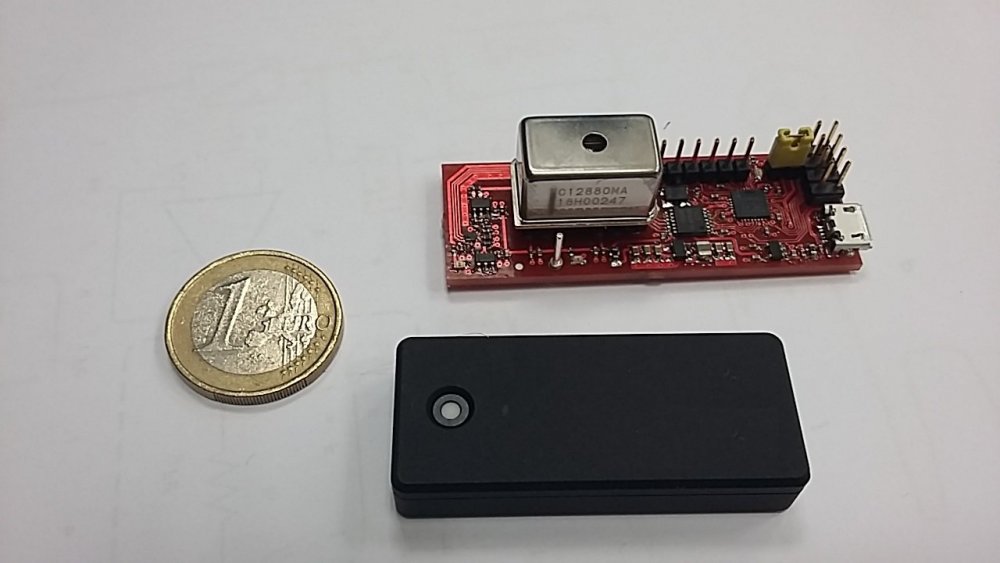
Hi Tony, I use only Lattice FPGA nowadays, mainly XO2 series. Best price for a load of features, and no external EEPROM stuff to handle. Don't use I2C for configuring, it is screwed up, and can brick the FPGA (had to manually fix all boards for our first subsea stuff to get SPI flashing working). If you use SPI for configuring, forget about Lattice software, it is "just" writing some Flash rows (easy to handle even from an 8bit uC). See picture, it features a XO2-1200 reading out an Hamamatsu C12880MA spectrometer by 14bit ADC and SPI (quite big PCB due to power supply with LDO and stepup converter, and level converter for 5V spectrometer signals). XO2-7000 is prefered if you need more BRAMs, the 1200 is available in a nice handsolderable small package (limited I/O, indeed). For doing both user communication and flashing, you "just" have to wire SPI SCK, MOSI and MISO to dedicated sysConfig pins, and to normal I/Os in parallel (I always use my own VHDL SPI slave, not the macro one). Next, use CSN for flashing, and normal I/O for /CS in user mode. And don't forget the feature row, to enable SPI config. I use JTAG pins in dual use, so don't forget about JTAGEN. (Black box is a commercial spectrometer, as size comparison, it has unfortunately bad dark current values, so it is not suitable for long time exposure as we need it subsea - but silly enough it uses a XO3 FPGA )
-
Hi Tony, you are a telepath? I need two SPIs, where do you know from ? One is for user communication to FPGA, the other one for reflashing the FPGA Will try tomorrow. So far, Michael
-
Hi guys, just wanted to ask if the latest changes are in the build system already. I will need no PWM this time when we go subsea, but SPI instead, and for different issues I worked so far with a C1+ and SPI (as I had to complete setup already using this). So, it would be great to know if just a "compile your image" will work for SPI, and if not, how to get the necessary steps done. Any help is appreciated. @TonyMac32: if it helps, you can have one of my C2 as test setup. So far, Michael
