


5kft
-
Posts
264 -
Joined
-
Last visited
Content Type
Forums
Store
Crowdfunding
Applications
Events
Raffles
Community Map
Everything posted by 5kft
-
Exactly... Thanks again for looking further into this!
-
Agreed. @Igor, @martinayotte, @lanefu - apologies for the spam, but am looking for your thoughts...should we drop back to the FA mainline u-boot DDR clock rate for the NEO2, NEO Plus2, etc.? Yeah, the Black is great - it's a NEO Core2 base with a better regulator, plus eMMC. I use a number of these now. I like these boards because they are so tiny, low power, and the performance is great The little metal cases are awesome too.
-
Yes - the posts I mention above have some history regarding this (e.g., patch to bring the mainline 672 down to the FA 504). It looks like there was an original desire to run it at 504, then at some point in late 2017 people started overclocking, and it seemed to work... On my NEO2s, I couldn't get any failures at the default CPU clock rate (1.0GHz) at 576. I'd like to go conservative here for stability, but I'm not sure how people would feel going to 504 if 576 works fine. Can you confirm the clocks for the FA firmware that you tested with? It's worrisome if you could repro and it's at DDR 504/CPU 1.0GHz. BTW, I hammered my NEO2 Blacks running with the default (624), and they work without any issue - default clock goes to 1.37GHz. These boards are different as they use 32-bit DDR (two parts).
-
There are a number of other threads on this (and other forums) about this subject...I thought that this one was interesting: https://groups.google.com/forum/#!topic/linux-sunxi/coQGctAipgI (Icenowy patch to take it to 504MHz to match FA BSP) Also, this has some interesting history:
-
Great! It'd be interesting for you to try "openssl speed -multi 4" on your Opi Prime, and see if it makes it all the way through the run successfully without crashing (make sure you have sufficient cooling, and patience ). Personally I want a completely stable platform, which would mean take the most conservative route (e.g., possibly reduce the DDR clock even lower). I just got a crash on one board at 1.2GHz/576MHz, but it works fine if it isn't overclocked. However, if the overclock is just exposing a latent issue (as per @sfx2000's comment above), then we'd need to go lower... Any/all thoughts are appreciated regarding this...!
-
@sfx2000 - very nice sleuthing! I've spent some time with this, and was able to repro the crash consistently by dialing the DDR clock up a bit. I dialed the clock down and have been testing, and it is completely stable, even when overclocked - the openssl test can run to completion now, multiple times. (Note: I tested all of this on my "problematic" NEO2, which can only support a maximum overclock to 1.2GHz.) @Igor - it seems quite clear that the default 624MHz DDR clock is too high for this board. I've bisected the rates - e.g., 576MHz works great where 624MHz would crash intermittently. Now 576MHz may not actually be low enough, but at this point I think I'm going to go ahead and lower the H5 clocks to 576MHz (for the boards I have and can test), which will be more stable than the current 624MHz - please let me know if you disagree. The real driver for this is that even without overclocking sfx2000's board crashes with this test. Also, obviously is variance in boards/DDR...I'm also going to do some more research and testing and see if there isn't a more scientific process that we can use to determine the best DDR clock rate to use here...
-
In case it is helpful to users, I've checked in the new 1.2GHz max overclock overlay: https://github.com/armbian/build/commit/74c6adec7411ef4d6dfa2115d21378c84aecb488 Use it just like the 1.3GHz overclock overlay; no need to edit the default "/etc/default/cpufrequtils". E.g., relevant excerpt from "/boot/armbianEnv.txt" for NEO2 v1.1: ... overlay_prefix=sun50i-h5 overlays=usbhost1 usbhost2 gpio-regulator-1.3v cpu-clock-1.2GHz-1.3v ... Limiting the overclock to 1.2GHz on one of my NEO2s makes it completely stable as compared to 1.3GHz (e.g., using the "openssl speed -multi 4" SMP test). If anyone is interested, it'd be easy enough for me to add a 1.1GHz/1.3v overlay as well, just let me know
-
OK, thanks for the info! I ran the openssl test on a number of boards (two NEO2 v1.1s - one 512MB, one 1GB; also a modified Orange Pi Zero Plus2 H5). I was able to get it to consistently crash at 1.3GHz on one of the NEO2s, and reducing it to 1.2GHz with the overlay worked (I let it run for 5-10 min on each test). The other NEO2 worked OK at 1.3GHz; I didn't get enough run time on the Orange Pi Plus2 because it would keep overheating (critical shutdown at 100C). I ran the tests a few times and the behavior was consistent. I need to dig up a bigger heatsink/temporary fan for the Orange Pi to really test it...I have a number of other boards I could test this on, but I have to install heatsinks on them... Given that the 1.2GHz overlay solved the problem for my failing NEO2 (reproducible), I think that I'll go ahead and add it to the mainline. Using the overlay eliminates the need to edit /etc/default/cpufrequtils, just add the overlay to /boot/armbianEnv.txt. Unfortunately overclocking is pretty much "luck of the draw" in terms of the CPU...if your board is crashing at 1.2GHz/1.3v there isn't a lot we can do about it at that clockrate As a test you could try using the 1.3GHz overlay and reducing the MAX_SPEED in /etc/default/cpufrequtils to 1152000000 or 1104000000 and see if those are stable?
-
...ugh...I can relate... But it's so rewarding though, right?? Ah...then the overlay should help - keep me posted. Thanks!
-
Hi @sfx2000, if this is reproducible, please try removing "cpu-clock-1.3GHz-1.3v" from your armbianEnv.txt "overlays=" line, and see if the problem still occurs. If it does not, then pushing to 1.3GHz at 1.3v may be too much for your board... I've attached a new test overlay to this post that enables 1.2GHz at 1.3v; let me know if it fixes the problem (assuming that the 1.3GHz clock is the problem ). If this works then I can add it to the mainline. sun50i-h5-cpu-clock-1.2GHz-1.3v.dtbo
-
OK...interesting...it's a mystery then...
-
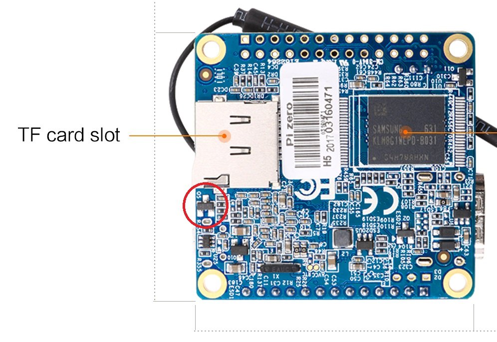
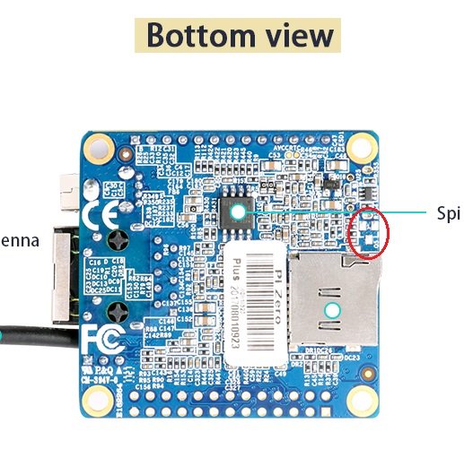
Indeed, but given that the board is clocking to 1.3GHz...: ### Boot system health: Time CPU load %cpu %sys %usr %nice %io %irq CPU C.St. 16:44:25: 1368MHz 0.38 41% 24% 12% 0% 3% 0% 30.4°C 0/8 16:44:26: 1368MHz 0.38 29% 3% 0% 1% 24% 0% 29.5°C 0/8 16:44:26: 1368MHz 0.38 23% 5% 0% 1% 16% 0% 29.2°C 0/8 16:44:26: 1368MHz 0.38 22% 5% 0% 0% 16% 0% 31.1°C 0/8 ...I'm wondering if these new Plus2 H3 boards don't properly switch the CPU to 1.3v. I.e., perhaps Xunlong stopped stuffing the "Q5 MOSFET" like their H5 version... If the CPU gets clocked to 1.3GHz+, and the core is still running at 1.1v, then that would explain the random freezes. (This is how I discovered this problem on the Plus2 H5s originally.) @Neko May, if you look at the underside of your H3 boards, is the red circled part present on them or missing? Again, it may be a long shot, but it's worth checking...
-
Unfortunately I don't have a Plus2 H3...but I've used other H3s and they've all been working great. Soooo...it is probably a long shot, but you could try mounting your SD card on your development PC, then change the maximum clock rate specified in /etc/default/cpufrequtils (MAX_SPEED) to 480000 in the card rootfs, then try booting again and see if that helps? Maybe there's there's a problem with clocking/power of these new boards...?
-
Yes, you need to use the ...plus2 config for the NEO Plus2. This board is quite different from the NEO2...
-
 That's odd...I just downloaded the image via https://dl.armbian.com/nanopifire3/Buster_legacy, wrote it to an SD card, and it boots without a problem: I2C_WriteByte nack returned I2C Device Address Write Abitration Error I2C_WriteByte nack returned I2C Device Address Write Abitration Error I2C_WriteByte nack returned I2C Device Address Write Abitration Error I2C_WriteByte nack returned I2C Device Address Write Abitration Error I2C_WriteByte nack returned I2C Device Address Write Abitration Error I2C_WriteByte nack returned I2C Device Address Write Abitration Error I2C_WriteByte nack returned I2C Device Address Write Abitration Error I2C_WriteByte nack returned I2C Device Address Write Abitration Error Wakeup Sub CPU 1234567 CPU Wakeup done! WFI is expected. CPU0 is Master! U-Boot 2016.01-armbian (Jan 20 2020 - 00:51:40 +0100) DRAM: 1 GiB MMC: NEXELL DWMMC: 0, NEXELL DWMMC: 1 loaded from SD, getting env from MMC 1 *** Warning - bad CRC, using default environment MIPI: display.0 HDMI: display.0, preset 0 (1280 * 720) HDMI: phy ready... LCD: [HDMI] dp.0.1 1220x680 16bpp FB:0x46000000 In: serial Out: serial Err: serial Hit any key to stop autoboot: 0 ** File not found /boot.scr ** ## Executing script at 40000000 Wrong image format for "source" command 1277 bytes read in 19 ms (65.4 KiB/s) ## Executing script at 40000000 Boot script loaded from SD card 1 142 bytes read in 16 ms (7.8 KiB/s) 48642 bytes read in 27 ms (1.7 MiB/s) Loading DTB 7764891 bytes read in 357 ms (20.7 MiB/s) 15507464 bytes read in 686 ms (21.6 MiB/s) ## Loading init Ramdisk from Legacy Image at 49000000 ... Image Name: uInitrd Image Type: AArch64 Linux RAMDisk Image (gzip compressed) Data Size: 7764827 Bytes = 7.4 MiB Load Address: 00000000 Entry Point: 00000000 Verifying Checksum ... OK ## Flattened Device Tree blob at 48000000 Booting using the fdt blob at 0x48000000 Loading Ramdisk to 7d7f9000, end 7df60b5b ... OK Loading Device Tree to 000000007d7ea000, end 000000007d7f8e01 ... OK Starting kernel ... Armbian 20.02.0-rc0 Buster ttySAC0 nanopifire3 login: One strange thing I see about your boot log is that the u-boot is pretty old: The u-boot in the latest image download is just a few days old from today, so it looks like you're booting a corrupted image...?
 -
Kernel 5.5.0-rc2 freezes on Orange PI Plus 2
5kft replied to IanH's topic in Advanced users - Development
For what it's worth, I've been running 5.5.0-rc2 on a number of NanoPi boards (NEO 2s and NEO 2 Blacks) for several weeks now, including one running mosquitto+Influx+Grafana+nginx+a lot of Python processes, and they've all worked flawlessly. -
OK, thanks! As I figured, I need to dive in deeper. I'm curious about changes like this, for example: https://lkml.org/lkml/2019/4/3/9... Looks like I have another weekend project to do!
-
Sure! https://forum.armbian.com/topic/4330-spi-gpio-chip-select-support/ - mid-way in the thread you did some nice debugging into the kernel regarding the initialization of CS. I think I need to do a similar thing to figure out why it simply isn't initializing/working... Perhaps there is no relation, but without digging into spi-gpio yet I'm wondering why it wouldn't initialize correctly...?? "gpioinfo" shows the overlay initialization working in terms of GPIO allocation: line 63: unnamed unused input active-high line 64: unnamed "mosi" output active-high [used] line 65: unnamed "miso" input active-high [used] line 66: unnamed "sck" output active-high [used] line 67: unnamed "spi0 CS0" output active-low [used] line 68: unnamed unused input active-high ...but for example measuring line 67 (PC3) the line is low, when it should be high. Very strange...! Yes, my original test was using several other GPIOs (e.g., PG6/7 for CSN)...same effect.
-
I'm wondering if anyone has had any luck using spi-gpio to bitbang SPI on the H5... @martinayotte, I found a forum thread from a few years ago where you seemed to be looking at this area - perhaps you have an idea? Doing a typical spi-gpio DT overlay for this properly loads the spi-gpio and spi-bitbang drivers, creates /dev/spidev0.0, and allocates the gpios (verified via gpiod)...but the first problem I see is that the CS line is simply not working (cs-gpios below)...? /dts-v1/; /plugin/; / { fragment@0 { target-path = "/"; __overlay__ { spi { compatible = "spi-gpio"; #address-cells = <1>; #size-cells = <0>; ranges; mosi-gpios = <&pio 0 64 0>; /* PC0 */ miso-gpios = <&pio 0 65 0>; /* PC1 */ sck-gpios = <&pio 0 66 0>; /* PC2 */ cs-gpios = <&pio 0 67 1>; /* PC3 */ num-chipselects = <1>; status = "ok"; spidev { compatible = "spidev"; reg = <0>; spi-max-frequency = <500000>; }; }; }; }; }; I'm testing this on a NEO2 using dev kernel 5.3.8, and in this case I am re-using the same standard SPI lines for the HW SPI - this way I can switch between the two easily for testing. Standard HW SPI works great, of course, but the spi-gpio version doesn't. (I tested on other GPIO lines as well and the result is the same.) I hooked the CS, CLK, MOSI, and MISO lines to my scope, and did a test write spi_test through /dev/spidev0.0, and it appears that CLK is properly working, as is the test data transferred via MOSI (at least I'm seeing data bits coming across). But CS simply seems to not be working - I can't trigger properly on it (either high or low). Right off, measuring it shows it as low, when by default it should be high... I am not an expert by any means in this area, so any help/pointers/advice/thoughts would be greatly appreciated! Thanks!
-
I'm just catching up on this topic... I don't have access to my Zero Plus at the moment but from the picture on Xunlong's site (and my previous experience) it looks like this board has the same HW limitation as the Plus2 - the missing Q5 MOSFET (see red oval highlight in this picture): This problem/limitation is described in this thread: @Darkyere, if it in fact is the case that this part is not included on this board, then unfortunately your board will be limited to a maximum of 1008MHz (for reliable operation). According to the schematic (https://linux-sunxi.org/images/6/67/ORANGE_PI-ZERO-PLUS_V1_0_Schematic.pdf, page 7), the power circuit does include the switching regulator, so it should be capable of providing 1.3v if this part were installed. (Again, refer to the thread I mentioned previously for all details about this.) Igor's guidance of specifying the 1.3v regulator overlay alone is a workaround that will enable the higher clockrate to 1.0GHz. However, without the Q5 MOSFET installed, do not specify the 1.3GHz overclock overlay, as then your board will certainly crash (as you noticed)
-
Thanks @Igor! I looked into this and it works because the default CPU opp table requires 1.32v starting at clock frequency 1104MHz; this voltage is higher than the 1.30v provided by the regulator overlay, so the higher clock rates will not be enabled. I also confirmed that this works fine on my unmodified board as well
-
Hi @guidol, I've pushed the change to sunxi-dev: https://github.com/armbian/build/commit/f1cdca27530ed401ff3f5f301aae46155704c85d Enjoy!
-
Makes sense; I'll merge this new overlay patch in with the existing 1.3GHz patch and should be able to push it tonight. Thanks for testing it!
-
@Igor - is this a safe change to make for the OPi Zero Plus2 H5? The default H5 CPU frequency opp table now goes to ~1.4GHz, and by adding this regulator overlay you're telling the system that the board has a 1.3v regulator, which by default it likely will not: Perhaps the Armbian default MAX_SPEED= cpufrequtils value will gate this so it will be fine, but I'm not sure if this will happen early enough? I wouldn't be able to check on my unmodified OPi Plus2 physical board until tonight. My thinking in making this an optional overlay was so that people had to really know what they are doing in order to overclock...but perhaps I am being too conservative Just want to make sure...thanks!
-
Hi @guidol, I made a quick build patch and created two test 1.1v overclock overlays for you for testing. I have attached them to this message in a tarfile. These are built against the 5.3.7 Armbian sunxi-dev kernel; they will not work with -next 4.19 as the opp table definitions are different between these kernels. You can extract this tarfile from the root of your board ("/"), and two overlay files will be extracted into "boot/dtb-5.3.7-sunxi64/allwinner/overlay/": -rw-r--r-- root/root 478 2019-10-30 03:19 boot/dtb-5.3.7-sunxi64/allwinner/overlay/sun50i-h5-cpu-clock-1.0GHz-1.1v.dtbo -rw-r--r-- root/root 562 2019-10-30 03:19 boot/dtb-5.3.7-sunxi64/allwinner/overlay/sun50i-h5-cpu-clock-1.1GHz-1.1v.dtbo Specify the desired one just like for my 1.3GHz overclock overlay; e.g., add these lines to your "/boot/armbianEnv.txt" (this is an example): overlay_prefix=sun50i-h5 overlays=usbhost1 usbhost2 cpu-clock-1.0GHz-1.1v I have included both a 1.0GHz overclock overlay as well as a 1.1GHz overclock overlay. Speeds above 816MHz are set at 1.1v. NOTE: I'm not sure if 1.1GHz at 1.1v is pushing it too much, but I figured you could give it a try if you are feeling adventurous I did a quick test of both of these and they loaded fine, set the clock maximums fine, cpufreq-info works, the board works, etc. Give these a try and let me know how it goes... If these work I could add these to the Armbian build as additional overclock options. H5-overclock-test-dtbs-1.1v.tar.gz