Search the Community
Showing results for tags 'orangepizero'.
-
... [ OK ] Finished Set console font and keymap. [ OK ] Finished Helper to synchronize boot up for ifupdown. Starting Raise network interfaces... [ OK ] Started udev Kernel Device Manager. [ OK ] Found device /dev/ttyGS0. [ 14.547006] thermal thermal_zone0: binding zone cpu_thermal with cdev thermal-cpufreq-0 failed:-22 I just installed Armbian Focal on my Orange Pi Zero and i receive this error on startup, then the boot stops here. It did pass this step a couple times but 90% of the time it will not boot. Thanks in advance, //Hasan
-
 Hello, i update my OrangePiZero OS from Linux 5.10.43-sunxi to Linux 5.10.60-sunxi my screen fbtft spi lcd stop working , the screen is black. If there is a solution to this issue I would love to get help, thanks! here my configuration (work on 5.10.43). (Armbianmonitor link of 5.10.43 on top) (Armbianmonitor link of 5.10.60 Attached as a file ) fbtft.dts /dts-v1/; /plugin/; / { compatible = "allwinner,sun8i-h3"; fragment@0 { target = <&spi1>; __overlay__ { status = "okay"; }; }; fragment@1 { target = <&pio>; __overlay__ { spi1_cs_pins: spi1_cs_pins { pins = "PA13"; function = "gpio_out"; }; opiz_display_pins: opiz_display_pins { pins = "PA7", "PA2", "PA6"; function = "gpio_out"; }; }; }; fragment@2 { target = <&spi1>; __overlay__ { /* needed to avoid dtc warning */ #address-cells = <1>; #size-cells = <0>; pinctrl-0=<&spi1_pins &spi1_cs_pins>; cs-gpios=<&pio 0 13 1>; opizdisplay: opiz-display@0{ compatible = "ilitek,ili9341"; reg = <0>; pinctrl-names = "default"; pinctrl-0 = <&opiz_display_pins>; spi-max-frequency = <32000000>; rotate = <270>; bgr; fps = <30>; buswidth = <8>; reset-gpios = <&pio 0 7 1>; dc-gpios = <&pio 0 2 0>; led-gpios= <&pio 0 6 0>; debug = <5>; status="okay"; }; }; }; __overrides__ { speed = <&opizdisplay>,"spi-max-frequency:0"; rotate = <&opizdisplay>,"rotate:0"; fps = <&opizdisplay>,"fps:0"; debug = <&opizdisplay>,"debug:0"; }; }; /boot/armbianEnv.txt is: verbosity=1 bootlogo=true console=serial overlay_prefix=sun8i-h3 overlays=analog-codec i2c0 uart1 uart2 user_overlays=fbtft mcp7940 usbstoragequirks=0x2537:0x1066:u,0x2537:0x1068:u 1.txt
 -
My third Orange Pi Zero came last week, yesterday I plugged it and had heating issues... So I started reading, learning and testing.... Setup: OPiZ-1: 256 MB, no SPI flash - Has extension board plugged - for comparison OPiZ-2: 512 MB, with SPI flash OPiZ-3: 256 MB, with SPI flash (new one with problem) Test conditions: All with (newish) Sandisk Ultra 16 GB Class 10 All new formatted (SD Formatter) and burned/validated (Etcher v1.0.0) with Armbian_5.25_Orangepizero_Debian_jessie_default_3.4.113.img All on my desk - side by side, ambient temperature 25.0-25.1 C (20 cm from boards, no air flow) No case, no passive/active cooling Power supply 7 port 5V 36W total, 2.4A per port (wait, wait, I tried others, separated etc - I'm testing them with USB V/A/W tester - 5.2-5.3V / 0.260-0.350 A) First install done, rebooted, apt-get update && apt-get upgrade'd, rebooted, tested
-
(Finally this forum lets me enter a new topic. It's failing most of the time, making it really hard to solve my actual problem if the infrastructure also fails.) I'm using an Orange Pi Zero board and try to make it talk to a radio module via SPI. The whole thing already works on a Raspberry Pi so the module and cabling is correct. But the module doesn't respond to requests on the Orange Pi. Since this doesn't do anything, I searched for issues like this and along the way found an SPI loopback tool. I tried it and it returned all zeros. The tool readme suggests that the MOSI and MISO pins are not connected, but they are. I checked and resoldered those pins and connected both with a jumper. The hardware is 100% correct. It must be the software that doesn't understand the SPI interface here. The same tool shows a correct echo on the RasPi. I also found another topic here about the Allwinnder H6 chip where a patch in Armbian was necessary to resolve the same issue. I couldn't respond there due to a permanent forum outage and then lost the link. So I believe that the same error is in the Orange Pi Zero image. I didn't understand what was changed there, something deep within the system. The armbianmonitor -u command failed with an internal server error response, so I uploaded the logs elsewhere. The Google form in front of this bug report recommended paste.debian.net but that service is unsuitable because its length limit of 150 kB is not sufficient.
-
Hi, I'm using an Orange PI ZERO HC2 + and usb (mt7601u) wifi dongle to create a hotspot. The configuration is as follow <HOTSPOT>WLAN0 [ Orange PI ZERO HC2+] WLAN1 <connected to my box> At startup when hostapd is launched to create the hotspot i get the following output . See below <HOSTAPD ERROR>. My hostapd.conf is below. Wlan0 use for xradio_wlan as physical driver Wlan1 use for mt7601 as physical drive I did some testing. I have the exact same config with a pi3. And have no problem. I tested the hostapd provided with the orange pi on the pi3, it works no problem. On the orange PI, If i do it the other way round : wlan1 to deal with hotspot, wlan0 to connect to my box. <HOTSPOT>WLAN1 [ Orange PIZERO ] WLAN0 <connected to my box> I get the same error. So its does not depend on the underneath driver ( wradio_wlan, or mt7601u). So it looks like something fishy with the driver nl80211 declared in the hostapd.conf. Any help would be appreciated. Note: i guess its easy to reproduce, use my hostapd.conf below: hostapd myhostapd.conf # HOSTAPD ERROR -------------------------------------------------------------------------------------- hostapd -Kd myhostapd.conf random: getrandom() support available Configuration file: nfx-hostapd.conf nl80211: Supported cipher 00-0f-ac:1 nl80211: Supported cipher 00-0f-ac:5 nl80211: Supported cipher 00-0f-ac:2 nl80211: Supported cipher 00-0f-ac:4 nl80211: Supported cipher 00-0f-ac:10 nl80211: Supported cipher 00-0f-ac:8 nl80211: Supported cipher 00-0f-ac:9 nl80211: Supported cipher 00-0f-ac:6 nl80211: Supported cipher 00-0f-ac:13 nl80211: Supported cipher 00-0f-ac:11 nl80211: Supported cipher 00-0f-ac:12 nl80211: Using driver-based off-channel TX nl80211: Driver-advertised extended capabilities (default) - hexdump(len=8): 00 00 00 00 00 00 00 40 nl80211: Driver-advertised extended capabilities mask (default) - hexdump(len=8): 00 00 00 00 00 00 00 40 nl80211: interface wlan0 in phy phy1 nl80211: Set mode ifindex 4 iftype 3 (AP) nl80211: Failed to set interface 4 to mode 3: -95 (Operation not supported) nl80211: Try mode change after setting interface down nl80211: Set mode ifindex 4 iftype 3 (AP) nl80211: Failed to set interface 4 to mode 3: -95 (Operation not supported) nl80211: Interface mode change to 3 from 0 failed nl80211: Could not configure driver mode nl80211: deinit ifname=wlan0 disabled_11b_rates=0 nl80211: Remove monitor interface: refcount=0 netlink: Operstate: ifindex=4 linkmode=0 (kernel-control), operstate=6 (IF_OPER_UP) nl80211: Set mode ifindex 4 iftype 2 (STATION) nl80211 driver initialization failed. hostapd_interface_deinit_free(0x1eb0020) hostapd_interface_deinit_free: num_bss=1 conf->num_bss=1 hostapd_interface_deinit(0x1eb0020) wlan0: interface state UNINITIALIZED->DISABLED hostapd_bss_deinit: deinit bss wlan0 wlan0: AP-DISABLED hostapd_cleanup(hapd=0x1eb0d80 (wlan0)) wlan0: CTRL-EVENT-TERMINATING hostapd_free_hapd_data: Interface wlan0 wasn't started hostapd_interface_deinit_free: driver=(nil) drv_priv=(nil) -> hapd_deinit hostapd_interface_free(0x1eb0020) hostapd_interface_free: free hapd 0x1eb0d80 hostapd_cleanup_iface(0x1eb0020) hostapd_cleanup_iface_partial(0x1eb0020) hostapd_cleanup_iface: free iface=0x1eb0020 # --------myhostapd.conf interface=wlan0 driver=nl80211 #ht_capab= #driver=mt7601u #driver=mac80211 #driver=xradio_wlan ssid=CHEZLAUTRE hw_mode=g channel=6 ieee80211n=1 wmm_enabled=1 ht_capab=[HT40][SHORT-GI-20][DSSS_CCK-40] macaddr_acl=0 auth_algs=1 ignore_broadcast_ssid=0 wpa=2 wpa_key_mgmt=WPA-PSK wpa_passphrase=delautrecote rsn_pairwise=CCMP
-
 I installed the pyA20 library for controlling GPIO, but I can't get the internal pullup resistor to work anymore. I managed to get it working before, but after playing around with other things, it stopped working. I have a very simple circuit going on, with just a light switch and I'm trying to read the light switch using the internal pull-up resistor. I managed to get it working for a few days, but that's it. I gave up and decided to solder on my own 10K pull-up resistor from the input pin to 3.3V. To my surprise, the results were the same, the input pin floated. Everything works fine with an Arduino. This is all very strange and I hope someone can help me. I'm running all the latest software and kernel.
 -
I have found other treads that address "tv out not working" but none have been applicable. They point to files that are not on my system. It is an older orange pi zero. I have installed the latest armbian image. Here is the "lsb_release -a" return: Distributor ID: Ubuntu Description: Ubuntu 20.04.2 LTS Release: 20.04 Codename: focal I am currently operating headless and the login splash screen says "Welcome to Arbian 21.02.3 Focal with Linux 5.10.21-sunxi" I am trying to use the 13 pin connector. Pin 2 = ground (shield) and Pin 9 = video signal (center conductor) I have found forum threads about enabling the tv out but ... My current installation does not have a /boot/script.bin file ... Other forum threads also refer to files that I do not have. One thread says: ("the OPZ will not use the tvout port, unless you add "tv" on the /etc/modules file") I DO have the /etc/modules file and I tried adding the letters "tv" on the second line of my /etc/modules file but still no output. Other threads talk about editing the fex file but I can't get the fex editor compliled and installed using their instructions. Can anyone offer some suggestions? Thanks in advance!
-
Hello there. I have problems with connecting device with 1-wire protocol. Device: DHT11 Temperature-Humidity Sensor - It is Arduino version with pullup on the board. Board: Orange Pi Zero LTS (H2+) System: Linux orangepizero 5.10.21-sunxi #21.02.3 SMP Mon Mar 8 00:28:04 UTC 2021 armv7l armv7l armv7l GNU/Linux Based on instructions im preformed some steps: 1) Through armbian-config im enabled w1-gpio 2) Installed gpio app to get info about ports: +-----+-----+----------+------+--Orange Pi Zero--+------+----------+-----+-----+ | H2+ | wPi | Name | Mode | V | Physical | V | Mode | Name | wPi | H2+ | +-----+-----+----------+------+---+----++----+---+------+----------+-----+-----+ | | | 3.3v | | | 1 || 2 | | | 5v | | | | 12 | 8 | SDA.0 | ALT3 | 0 | 3 || 4 | | | 5V | | | | 11 | 9 | SCL.0 | ALT3 | 0 | 5 || 6 | | | 0v | | | | 6 | 7 | GPIO.7 | ALT3 | 0 | 7 || 8 | 0 | ALT3 | TxD3 | 15 | 198 | | | | 0v | | | 9 || 10 | 0 | ALT3 | RxD3 | 16 | 199 | | 1 | 0 | RxD2 | ALT3 | 0 | 11 || 12 | 0 | ALT3 | GPIO.1 | 1 | 7 | | 0 | 2 | TxD2 | ALT3 | 0 | 13 || 14 | | | 0v | | | | 3 | 3 | CTS2 | ALT3 | 0 | 15 || 16 | 0 | ALT3 | GPIO.4 | 4 | 19 | | | | 3.3v | | | 17 || 18 | 0 | ALT3 | GPIO.5 | 5 | 18 | | 15 | 12 | MOSI | ALT3 | 0 | 19 || 20 | | | 0v | | | | 16 | 13 | MISO | ALT3 | 0 | 21 || 22 | 0 | ALT3 | RTS2 | 6 | 2 | | 14 | 14 | SCLK | ALT3 | 0 | 23 || 24 | 0 | ALT3 | CE0 | 10 | 13 | | | | 0v | | | 25 || 26 | 1 | IN | GPIO.11 | 11 | 10 | +-----+-----+----------+------+---+---LEDs---+---+------+----------+-----+-----+ | 17 | 30 | STAT-LED | OUT | 0 | 27 || 28 | | | PWR-LED | | | +-----+-----+----------+------+---+-----+----+---+------+----------+-----+-----+ | H2+ | wPi | Name | Mode | V | Physical | V | Mode | Name | wPi | H2+ | +-----+-----+----------+------+--Orange Pi Zero--+---+------+---------+-----+--+ 3) I have changed /boot/armbianEnv.txt verbosity=1 bootlogo=false console=serial disp_mode=1920x1080p60 overlay_prefix=sun8i-h3 overlays=usbhost2 usbhost3 w1-gpio rootdev=UUID=d522be3f-9ac0-489b-9d79-500c38e89c86 rootfstype=ext4 param_w1_pin=PA10 param_w1_pin_int_pullup=0 usbstoragequirks=0x2537:0x1066:u,0x2537:0x1068:u 4) Also changed CPU /etc/default/cpufrequtils ENABLE=true MIN_SPEED=1400000 MAX_SPEED=1400000 GOVERNOR=interactive As you can see, im using PA 10 port and i can see at "gpio readall" value of "V" sign, when im disconnecting wire from board - it is going to be zero, after reconnection it is again going to be 1. Thats showing thats im using correct port. Now im trying to analyze logs at dmesg, and i see this related information, in case loading WITH CONNECTED WIRE [ 12.182141] Driver for 1-wire Dallas network protocol. [ 12.199201] gpio-10 (onewire@0): enforced open drain please flag it properly in DT/ACPI DSDT/board file In case of DISCONNECTED WIRE LOG WILL BE: [ 12.182141] Driver for 1-wire Dallas network protocol. [ 12.199201] gpio-10 (onewire@0): enforced open drain please flag it properly in DT/ACPI DSDT/board file [ 614.571146] w1_master_driver w1_bus_master1: w1_search: max_slave_count 64 reached, will continue next search. [ 661.463966] w1_master_driver w1_bus_master1: Attaching one wire slave 00.800000000000 crc 8c [ 661.474854] w1_master_driver w1_bus_master1: Family 0 for 00.800000000000.8c is not registered. [ 720.081030] w1_master_driver w1_bus_master1: Attaching one wire slave 00.400000000000 crc 46 [ 720.091987] w1_master_driver w1_bus_master1: Family 0 for 00.400000000000.46 is not registered. [ 766.913878] w1_master_driver w1_bus_master1: Attaching one wire slave 00.c00000000000 crc ca [ 766.924868] w1_master_driver w1_bus_master1: Family 0 for 00.c00000000000.ca is not registered. [ 837.355159] w1_master_driver w1_bus_master1: Attaching one wire slave 00.200000000000 crc 23 [ 837.366059] w1_master_driver w1_bus_master1: Family 0 for 00.200000000000.23 is not registered. [ 895.996491] w1_master_driver w1_bus_master1: Attaching one wire slave 00.a00000000000 crc af If will connect WIRE again in this case, messages stopping appear. There are no any success with experimenting on changing GPIO port or Device (i have multiple boards and devices) or pullup Core debugging: After getting all experiments unsuccessful im going and check linux core on driver level. There are function thats making search of connected devices: https://github.com/analogdevicesinc/linux/blob/master/drivers/w1/w1.c /** * w1_search() - Performs a ROM Search & registers any devices found. * @dev: The master device to search * @search_type: W1_SEARCH to search all devices, or W1_ALARM_SEARCH * to return only devices in the alarmed state * @cb: Function to call when a device is found * * The 1-wire search is a simple binary tree search. * For each bit of the address, we read two bits and write one bit. * The bit written will put to sleep all devies that don't match that bit. * When the two reads differ, the direction choice is obvious. * When both bits are 0, we must choose a path to take. * When we can scan all 64 bits without having to choose a path, we are done. * * See "Application note 187 1-wire search algorithm" at www.maxim-ic.com * */ void w1_search(struct w1_master *dev, u8 search_type, w1_slave_found_callback cb) On this function im seeing thats search going until dev->max_slave_count will be reached and if no devices found we will see: dev_info(&dev->dev, "%s: max_slave_count %d reached, ""will continue next search.\n", __func__,dev->max_slave_count); Everything looks like correct, so we getting error in case of no devices found, but i see the problem thats on next iteration im getting this errors: [ 766.913878] w1_master_driver w1_bus_master1: Attaching one wire slave 00.c00000000000 crc ca [ 766.924868] w1_master_driver w1_bus_master1: Family 0 for 00.c00000000000.ca is not registered. Because this errors appear in case of this condition: if ( (triplet_ret & 0x03) != 0x03 ) { if ((desc_bit == last_zero) || (last_zero < 0)) { last_device = 1; dev->search_id = 0; } else { dev->search_id = rn; } desc_bit = last_zero; cb(dev, rn); } on callback function. Based on code research i see thats some "break" on data reading cycle fired or something, thats why im not getting error messages on dmesg in case or WIRE CONNECTED. But w1_master_attempts is increasing, so search cycles going fine Questions: 1) So core is found some device on empty port and trying to connect, how this possible? And why? 2) Why there are no logs in case of connected wire to port but problem with connection? I see debug logs there but i think i need to recompile core to check it. 3) How to make my 1-wire works?
-
Hi there. I use Orange Pi zero as home print server. It works for few months for now and I am very pleased with that. Although, my printer falls into deep sleep after printing (it's Brother HL-1110EW) and cannot be woken up by the server. I have to start printer manually to print next printouts. Thus I wanted to install tea4cups to drive a relay turning the printer on and off when needed. I installed the WiringOP-zero (from here: https://github.com/xpertsavenue/WiringOP-Zero) but then strange things become to happen. I connected temporarily a LED diode to indicate the changes of the GPIO. (GPIO-7 and GND). The LED is on all the time, no matter what command I send. Even if "gpio readall" shows "0" state on GPIO-7 the led still is on. I tried to push the values through "echo": But also without success. That means gpio readall still shows changes in the table but there are no physical changes on the pin (the voltage still is on). Then I thought that maybe there is no kernel module loaded, but I can see that w1-gpio is loaded: lsmod Module Size Used by aes_arm_bs 20480 2 crypto_simd 16384 1 aes_arm_bs ccm 20480 6 xradio_wlan 110592 1 mac80211 532480 1 xradio_wlan sun4i_gpadc_iio 16384 0 cfg80211 491520 2 mac80211,xradio_wlan industrialio 53248 1 sun4i_gpadc_iio zram 24576 2 sun8i_thermal 16384 0 sunxi_cedrus 32768 0 rfkill 20480 3 cfg80211 libarc4 16384 1 mac80211 v4l2_mem2mem 20480 1 sunxi_cedrus videobuf2_dma_contig 20480 1 sunxi_cedrus videobuf2_memops 20480 1 videobuf2_dma_contig videobuf2_v4l2 20480 2 sunxi_cedrus,v4l2_mem2mem videobuf2_common 40960 3 sunxi_cedrus,v4l2_mem2mem,videobuf2_v4l2 w1_gpio 16384 0 wire 32768 1 w1_gpio cn 16384 1 wire uio_pdrv_genirq 20480 0 uio 16384 1 uio_pdrv_genirq cpufreq_dt 20480 0 usb_f_acm 20480 1 u_serial 24576 3 usb_f_acm g_serial 16384 0 libcomposite 45056 2 g_serial,usb_f_acm ip_tables 24576 0 x_tables 24576 1 ip_tables autofs4 36864 2 pwrseq_simple 16384 1 sunxi 16384 0 phy_generic 20480 2 sunxi Then I started to read forums, including this one. Still no clue what is happening, I did not find any similar case. I run out of ideas -maybe anyone would have some? Oh, I forgot one thing that may be interesting - driving onboard red led actually works. (gpio 30) EDIT: I changed the driving pin for pin9 and it works fine. Pin 7 is damaged or anything? Dunno.
-
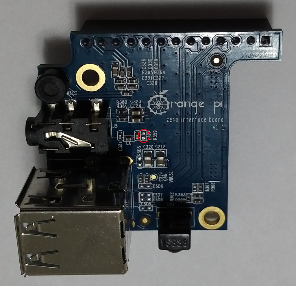
 Having invested many, many hours getting the video out to work on my recently purchased Orange Pi Zero kit, I'd like to leave this heads up for the next person having trouble with video out. In my case, none of the advice I could find in this forum or elsewhere seemed to make any difference. If you find yourself in a similar situation, here are some things you should know. The latest Armbian images for the OrangePi Zero enable composite video out by default. It should just work. (Well at least the Ubuntu image -- I never actually verified Debian Jesse worked after I fixed my expansion board.) You should NOT need to fiddle with /etc/modules or .fex files. Although that bit of information can be found in other posts on this forum, it took me a while to stumble across it, so I'm calling it out here. Don't trust the expansion board or your AV cable. If you hook everything up and don't get video right away, the first thing to try is connecting your monitor directly to the GND and TV-OUT pins on the 13-pin connector. Regretfully, I only resorted to this after much time spent futzing with other things. In my case, not only was my expansion board borked, but the supposedly Zune/RaspberryPi compatible AV cable I got from Amazon actually had the ground and video swapped on the yellow RCA plug. The expansion board adds a bit of circuitry to the tv-out line, an inductor, two capacitors and a resistor, which I'm guessing is some sort of filter that attempts to "clean up" the video signal. Being that you can hook up video directly to the OrangePi Zero without an expansion board, it would seem this filtering is entirely optional. I happened to notice (while checking continuity with a multitester) that the resistance between the GND and TV-OUT pins on the bare, unpowered OrangePi Zero board was effectively an open circuit, but when the expansion board was installed, it changed to approximately 50 ohms. It seemed to me that all this would accomplish is to pull the composite video signal very close to ground and hold it there. On a hunch, I took an Xacto knife and carefully scraped R359 from the filter circuit off of the expansion board. This did the trick. Now, with a proper AV cable, my monitor could pick up a signal on its CVBS port. I've attached a picture of the expansion board with the location of this resistor circled in red. Maybe I just had a bad resistor, but if you've tried everything else, it may be worth knowing that removing this resistor can't hurt and is worth trying.
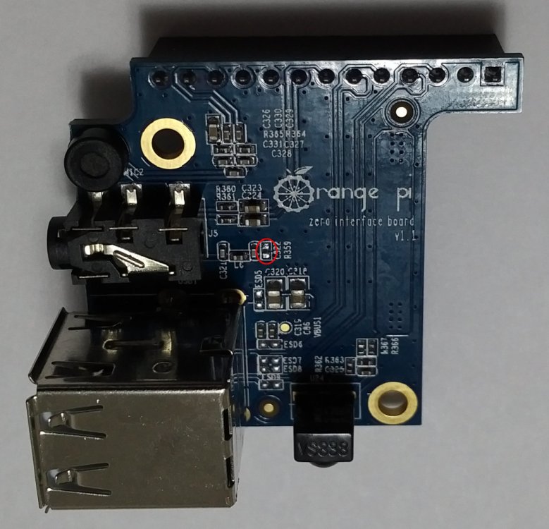
-
Hi, As you can see in the armbianmonitor output, an error prevents from using the Spi with the Orange pi Zero board using a newly downloaded Armbian image. The output refers to the Armbian-Hirsute image (the last one tested) but the same error also occurs with the Buster and Focal images. Unfortunately I don't have the knowledge to correct the following error myself: [3.349869] sun6i-spi 1c68000.spi: chipselect 0 already in use [3.349901] spi_master spi0: spi_device register error / soc / spi @ 1c68000 / flash @ 0 [3.349953] spi_master spi0: Failed to create SPI device for / soc / spi @ 1c68000 / flash @ 0 The only commands executed in a fresh image are: 1) armbian-config to activate spidev and 2) added two Spi parameters in the armbianEnv.txt file . I hope that someone more experienced than me (and there are many in the forum!) Will suggest the way to avoid this issue or that with the next Armbian release it won't show up anymore. Thank you all.
-
I'm trying to get an MCP2515 working with an Orange Pi Zero LTS H2+. Everything seems to go well until I try to bring up the can0 interface using the command ip link set can0 up type can bitrate 500000 Once the command is entered, it never returns. Control+C doesn't do help. New SSH sessions fail to start, but pinging the IP address works fine. Trying ifconfig from the serial terminal will also fail to return. Trying to shutdown after the "ip link set..." command, the shutdown procedure takes a long time, and eventually sends [ 4320.026984] systemd-shutdown[1]: Waiting for process: ifdown, wpa_supplicant, NetworkManager, ip The image was built using the git clone and config commands, per https://docs.armbian.com/Developer-Guide_Build-Preparation/, using a Lubuntu VM. Image is "Current", "Ubuntu Focal". The overlay was based on https://github.com/armbian/sunxi-DT-overlays/blob/master/examples/spi-mcp251x.dts, with target = <&spi0>; changed to target = <&spi1>; In dmesg, the MCP2515 appears to be working mcp251x spi1.0 can0: MCP2515 successfully initialized. Any tips on how to debug?
-
Hi I am using an OrangePi Zero 2+ with AllWinner H3 and i need both uart. I enable them with armbian-config and on pins Uart2 on pins 8 and 10 work fine bat uart1 on pins 11, 13 don't. The pin on this board is not the same as orangepi zero? I mast make some setup to make uart1 to work? auto@orangepizeroplus2-h3:~$ uname -a Linux orangepizeroplus2-h3 5.9.14-sunxi #20.11.3 SMP Fri Dec 11 20:31:12 CET 2020 armv7l armv7l armv7l GNU/Linux auto@orangepizeroplus2-h3:~$ cat /boot/armbianEnv.txt verbosity=1 bootlogo=false console=both disp_mode=1920x1080p60 overlay_prefix=sun8i-h3 overlays=i2c1 uart1 uart2 uart3 usbhost2 usbhost3 rootdev=UUID=f2961b16-88cc-46d0-8297-931c6211f21c rootfstype=ext4 usbstoragequirks=0x2537:0x1066:u,0x2537:0x1068:u auto@orangepizeroplus2-h3:~$ ls -al /dev/ttyS* crw--w---- 1 root tty 4, 64 Feb 26 07:57 /dev/ttyS0 crw-rw---- 1 root dialout 4, 65 Feb 26 07:58 /dev/ttyS1 crw-rw---- 1 root dialout 4, 66 Feb 26 07:58 /dev/ttyS2 crw-rw---- 1 root dialout 4, 67 Feb 26 07:56 /dev/ttyS3 crw-rw---- 1 root dialout 4, 68 Feb 26 07:56 /dev/ttyS4 crw-rw---- 1 root dialout 4, 69 Feb 26 07:56 /dev/ttyS5 crw-rw---- 1 root dialout 4, 70 Feb 26 07:56 /dev/ttyS6 crw-rw---- 1 root dialout 4, 71 Feb 26 07:56 /dev/ttyS7 auto@orangepizeroplus2-h3:~$ dmesg | grep tty [ 0.000000] Kernel command line: root=UUID=f2961b16-88cc-46d0-8297-931c6211f21c rootwait rootfstype=ext4 console=ttyS0,115200 console=tty1 hdmi.audio=EDID:0 disp.screen0_output_mode=1920x1080p60 consoleblank=0 loglevel=1 ubootpart= ubootsource=mmc usb-storage.quirks=0x2537:0x1066:u,0x2537:0x1068:u sunxi_ve_mem_reserve=0 sunxi_g2d_mem_reserve=0 sunxi_fb_mem_reserve=16 cgroup_enable=memory swapaccount=1 [ 0.000272] printk: console [tty1] enabled [ 2.333990] printk: console [ttyS0] disabled [ 2.334080] 1c28000.serial: ttyS0 at MMIO 0x1c28000 (irq = 40, base_baud = 1500000) is a 16550A [ 2.334160] printk: console [ttyS0] enabled [ 2.335312] 1c28400.serial: ttyS1 at MMIO 0x1c28400 (irq = 41, base_baud = 1500000) is a 16550A [ 2.336286] 1c28800.serial: ttyS2 at MMIO 0x1c28800 (irq = 42, base_baud = 1500000) is a 16550A [ 2.337239] 1c28c00.serial: ttyS3 at MMIO 0x1c28c00 (irq = 43, base_baud = 1500000) is a 16550A [ 4.955994] systemd[1]: Created slice system-serial\x2dgetty.slice. [ 5.613942] systemd[1]: Found device /dev/ttyGS0. [ 6.438922] systemd[1]: Found device /dev/ttyS0. auto@orangepizeroplus2-h3:~$ pyserial-miniterm /dev/ttyS2 --- Miniterm on /dev/ttyS2 9600,8,N,1 --- --- Quit: Ctrl+] | Menu: Ctrl+T | Help: Ctrl+T followed by Ctrl+H --- sdfsdf --- exit ---
-
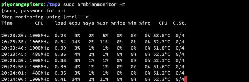
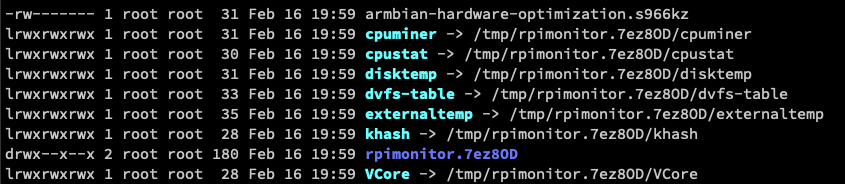
I used armbianmonitor -r on my OPi Zero just like I did previously on OPi One. On OPi One everything is working fine. On my zero it doesn't display all the information for CPU. It shows: CPU total: undefined% (Sys: undefined%, User: undefined%, I/O wait: undefined%, Nice: undefined%) CPU frequency: 1.008GHz DRAM frequency: Not available Governor: ondemand Active CPU cores: 4 Vcore: undefined If I run armbianmonitor -m it shows these data I checked Allwinner_H3_Extended.conf and I noticed that it reads files from /tmp (/tmp/cpustat, /tmp/disktemp, e.t.c) On my OPi One I see these files On OPi Zero there is no rpimonitor folder. I only see these armbian-hardware-optimization.OkJBzI systemd-private-0b4c896481294542b7b1cd8e7a270133-chrony.service-SHnE1R systemd-private-0b4c896481294542b7b1cd8e7a270133-haveged.service-qSLdic What could be the issue?
-
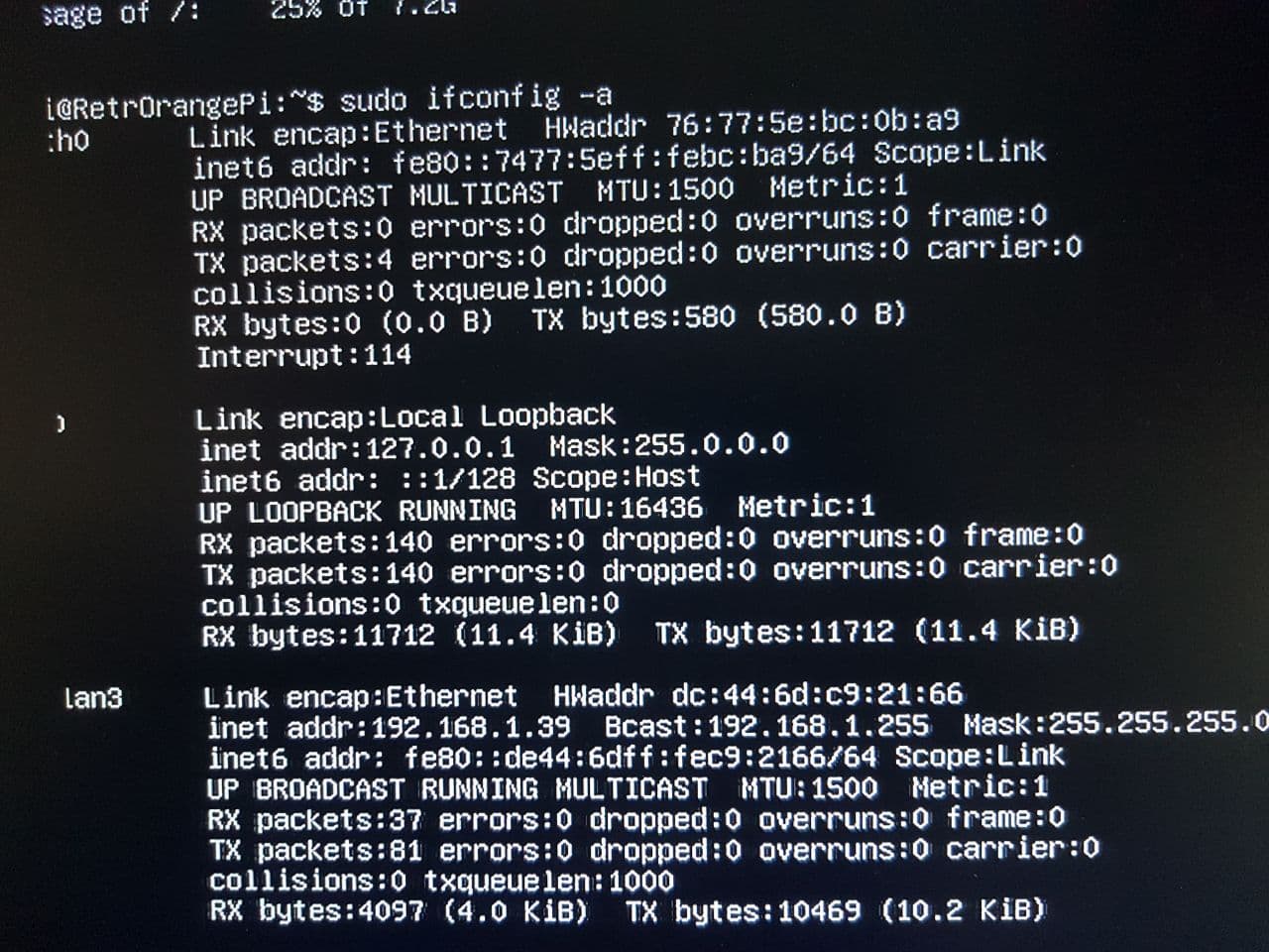
 Hello, I have problem that wireless interface only reachable when ethernet cable plugged to my orange pi zero. I use nmtui, to setup my WiFi connection. All connects fine and works. But when I disconnect ethernet cable, I lost also WiFi connection. I see this post: https://forum.armbian.com/topic/4098-orange-pi-zero-wifi-issues-when-disconnect-ethernet-cable/ But even after rebooting without ethernet cable, WiFi connnection doesn't work. Then in a new clean image, I try to run nmtui without connecting ethernet cable. WiFi connects without any errors, but doesn't work. Please, help!
-
Hi, i would like to read continously from Orangepi zero SPI. I download the latest kernel from https://www.armbian.com/orange-pi-zero/. Now i need to enable the SPI. I tried with changing my /boot/armbianEnv.txt file here i'm attaching it. Then i reboot and loged then i can see spidev0.0. But i want to use SPI1. How to enable SPI 1. armbianEnv.txt
-
 I'm running my Orange Pi Zero headless on Armbian Buster 20.11.6 Last check uptime was 6 days, but now I find its rebooted and I think this is due to unattended security packe upgrades. The package is installed unattended-upgrades/stable,now 1.11.2 all [installed] automatic installation of security upgrades Looking in /etc/apt/apt.conf.d 01autoremove 20auto-upgrades 70debconf 01autoremove-kernels 50apt-file.conf 71-armbian-no-recommends 02-armbian-compress-indexes 50command-not-found 81-armbian-no-languages 02-armbian-periodic 50unattended-upgrades Is it safe to just remove unattended-upgrades or is there a better method to prevent unattended-upgrades from running? Thanks in advance.
 -
 Hi I am trying to set up auto-login with enable desktop, using armbian-config as user root, and getting 'killed' once I select which under-priviledged user to enable. (There's two to choose from, and both behave the same with the same error reult). I couldn't find a known issue, please help! OPi Zero LTS 512MB / Armbian from armbian.com Sam
 -
I'm running Armbian Bionic on OPizero. I have a problem using arecord on the mic input. Audio codecs have been enabled but when I run following command to record I get a pcm read error arecord -D plughw:0,0 -d5 -f cd test.wav Recording WAVE 'test.wav' : Signed 16 bit Little Endian, Rate 44100 Hz, Stereo arecord: pcm_read:2103: read error: Input/output error There is no recording and file is just 44 bytes. pi@orangepizero:~$ ls -l test.wav -rw-r--r-- 1 pi pi 44 Jan 6 20:44 test.wav The output from this command never finishes after 3 seconds and I have to use ctrl+c to breakout: arecord -vvvv -d 3 /dev/null Recording WAVE '/dev/null' : Unsigned 8 bit, Rate 8000 Hz, Mono Plug PCM: Linear conversion PCM (S16_LE) Its setup is: stream : CAPTURE access : RW_INTERLEAVED format : U8 subformat : STD channels : 1 rate : 8000 exact rate : 8000 (8000/1) msbits : 8 buffer_size : 4000 period_size : 1000 period_time : 125000 tstamp_mode : NONE tstamp_type : MONOTONIC period_step : 1 avail_min : 1000 period_event : 0 start_threshold : 1 stop_threshold : 4000 silence_threshold: 0 silence_size : 0 boundary : 2097152000 Slave: Hardware PCM card 0 'H3 Audio Codec' device 0 subdevice 0 Its setup is: stream : CAPTURE access : MMAP_INTERLEAVED format : S16_LE subformat : STD channels : 1 rate : 8000 exact rate : 8000 (8000/1) msbits : 16 buffer_size : 4000 period_size : 1000 period_time : 125000 tstamp_mode : NONE tstamp_type : MONOTONIC period_step : 1 avail_min : 1000 period_event : 0 start_threshold : 1 stop_threshold : 4000 silence_threshold: 0 silence_size : 0 boundary : 2097152000 appl_ptr : 0 hw_ptr : 0 ^CAborted by signal Interrupt... arecord: pcm_read:2103: read error: Interrupted system call The commands work fine on Linux <Mint 19.3 (built on Ubuntu bionic). I first installed Armbian Buster but had same problem, which is why I tried Armbian Bionic After some digging I came up with this bug report: https://bugzilla.redhat.com/show_bug.cgi?id=472469 I'm out of ideas now,. I'm using OPiZero headless, no desktop and login via SSH. ArmbianMonitor logs uploaded at: https://bugzilla.redhat.com/show_bug.cgi?id=472469 Thanks in advance for any help with this.
-
Hi, we are trying to make our Orange PI zero with custom shield working with an MCP2518FD on board with SN65HVD23 tranceiver. We started from the normal kernel already built, but according to this thread we found that it must be activated at compile time. So we downloaded the repo and built the Armbian image with this CAN configuration: CONFIG_CAN=y CONFIG_CAN_RAW=y CONFIG_CAN_BCM=y CONFIG_CAN_GW=y CONFIG_CAN_J1939=y # # CAN Device Drivers # CONFIG_CAN_VCAN=y CONFIG_CAN_VXCAN=y CONFIG_CAN_SLCAN=y CONFIG_CAN_DEV=y CONFIG_CAN_CALC_BITTIMING=y CONFIG_CAN_FLEXCAN=y CONFIG_CAN_GRCAN=y CONFIG_CAN_SUN4I=y CONFIG_CAN_TI_HECC=y CONFIG_CAN_C_CAN=y CONFIG_CAN_C_CAN_PLATFORM=m CONFIG_CAN_CC770=y CONFIG_CAN_CC770_ISA=m CONFIG_CAN_CC770_PLATFORM=m CONFIG_CAN_IFI_CANFD=y CONFIG_CAN_M_CAN=y CONFIG_CAN_M_CAN_PLATFORM=y CONFIG_CAN_M_CAN_TCAN4X5X=y CONFIG_CAN_RCAR=y CONFIG_CAN_RCAR_CANFD=y CONFIG_CAN_SJA1000=y CONFIG_CAN_SJA1000_ISA=m CONFIG_CAN_SJA1000_PLATFORM=m CONFIG_CAN_SOFTING=y # # CAN SPI interfaces # CONFIG_CAN_HI311X=y CONFIG_CAN_MCP251X=y # end of CAN SPI interfaces # # CAN USB interfaces # CONFIG_CAN_8DEV_USB=y CONFIG_CAN_EMS_USB=y CONFIG_CAN_ESD_USB2=y CONFIG_CAN_GS_USB=y CONFIG_CAN_KVASER_USB=y CONFIG_CAN_MCBA_USB=y CONFIG_CAN_PEAK_USB=y CONFIG_CAN_UCAN=y # end of CAN USB interfaces CONFIG_CAN_DEBUG_DEVICES=y # end of CAN Device Drivers we currently have two problems: 1. At the physical interface level, the driver in this kernel version works only with MCP2515, but not with our MCP2518FD. After reading the following tread we found the original repository from which we copied the folder with the MCP2518FD drivers, but we can't compile them and include them in our kernel (because we don't know how to do it). 2. We cannot activate the CanBus interface with these commands (we get Cannot find device "can0"): ip link set can0 type can bitrate 2000000 fd off ip link can0 set can0 up Is there a guide on how to build and include the drivers we need? Once the driver has been loaded we could test the .dtbo and see if the MCP initializes correctly.
-
Hello, It's my first message, I'm very proud to be part of your community, Armbian is epic ! I'm trying to add a chinese screen copy to my orangepizero (H2+ cpu). This is my screen: https://www.aliexpress.com/item/32587995145.html (copie of https://www.waveshare.com/3.5inch-rpi-lcd-a.htm) 1) Yesterday i setup my screen on Armbian_5.91_Orangepizero_Debian_buster_next_4.19.59 with success with: nano /boot/armbianEnv.txt : overlays=spi-spidev spi-add-cs1 param_spidev_spi_bus=1 param_spidev_spi_cs=1 nano /etc/modules-load.d/fbtft.conf : fbtft fbtft_device nano /etc/modprobe.d/fbtft.conf : options fbtft_device rotate=90 name=piscreen speed=32000000 busnum=1 gpios=reset:2,dc:18 txbuflen=32768 fps=25 It created a framebuffer (fb0) which worked without problem. 2) I also tried with Armbian_20.05.3_Orangepizero_buster_current_5.4.45 with success with: nano /boot/armbianEnv.txt : overlays=spi-spidev spi-add-cs1 param_spidev_spi_bus=1 param_spidev_spi_cs=1 Create DTS file: And added to armbian with: armbian-add-overlay foo.dts After reboot, the screen worked too ! 3) But with the 5.9.14 kernel, it doesn't work ! (Armbian_20.11.3_Orangepizero_buster_current_5.9.14.img) I tried with DTS file + spi overlay in armbianEnv.txt, but nothing... This is my "dmesg | grep spi" : [ 3.223574] spidev@1 enforce active low on chipselect handle [ 3.224724] spi_master spi1: cannot find modalias for /soc/spi@1c69000/spidev@1 [ 3.224759] spi_master spi1: Failed to create SPI device for /soc/spi@1c69000/spidev@1 [ 10.585918] [drm] Initialized ili9486 1.0.0 20200118 for spi1.0 on minor 0 [ 12.495270] ili9486 spi1.0: [drm] fb0: ili9486drmfb frame buffer device This is my "ls /dev" As we can see i have "fb0" but no "spi1.1"... I already checked everything on the web and each topic in this forum, like that: I hope you can help me ! Thanks you a lot ! And sorry for my poor english, maybe I made some spelling mistakes !
-
I have OrangePi Zero 512 with Armbian Bionic. I hav econnected LED diode to GPIO PA12 pin. When I (re)boot the device, LED is automatically on. I have to switch it off then manually (with Python script). Is there any config file in Armbian to define which GPIO ports should be switched off?
-
 I just installed the latest Ubuntu Bionic Image with 4.x kernel, fully updated and upgraded. On Orange Pi Zero 1.4 512MB + IO expansion kit board Armbian 5.75 Ubuntu 18.04.2 LTS Linux orangepizero 4.19.20-sunxi #5.75 SMP Sat Feb 9 19:02:47 CET 2019 armv7l armv7l armv7l GNU/Linux `cat /proc/asound/cards` "No sound cards" In armbian-config, I enabled analog-codec, `update-initramfs, rebooted, but there's still no sound card. mocp complains there is no driver. speaker-test (starts like this) Playback device is default Stream parameters are 48000Hz, S16_LE, 1 channels Using 16 octaves of pink noise ALSA lib confmisc.c:767:(parse_card) cannot find card '0' Anyone know what the issue is? $ cat /boot/armbianEnv.txt verbosity=1 logo=disabled console=serial disp_mode=1920x1080p60 overlay_prefix=sun8i-h3 overlays=analog-codec usbhost2 usbhost3 w1-gpio rootdev=UUID=4cf6b202-4b00-45d6-b06a-8e235506621e rootfstype=ext4 usbstoragequirks=0x2537:0x1066:u,0x2537:0x1068:u $ cat /etc/asound.conf pcm.!default{ type hw card 0 } ctl.!default{ type hw card 0 } After the above and a reboot, I didn't have any codec modules loaded So I did this $ modprobe sun8i-codec-analog sun4i-codec $ aplay -l aplay: device_list:270: no soundcards found... $ cat /proc/asound/cards --- no soundcards --- $ ls -lah /dev/snd total 0 drwxr-xr-x 2 root root 60 Mar 20 06:04 . drwxr-xr-x 13 root root 14K Mar 20 06:04 .. crw-rw---- 1 root audio 116, 33 Mar 20 06:05 timer
 -
Hello, I have been struggling for some time with random freezes. I am running application with i2c0 Fram and UART1 for transferring/receiving data based on MAX3232. The freezes cause no response from Orange PI (debug UART too), only unplug power helps. I read that it may be a problem with powering but i tried many USB power adapters 2A, 3A and ATX power (28A) connected to GND and 5v, nothing helps. I have lowered cpu max frequency to 816Mhz and still the same. All necessary data uploaded via armbianmonitor.
-
 Hi. I've always had problem with the composite output (cutted edges) so i gave a try to the latest release. Unfortunatly the video does not show up at all. Anyone still using the old Opi0?