Search the Community
Showing results for tags 'orangepizeroplus2-h3'.
-
I have changed to 1080p and its almost stable but pull up any window that has maybe moderate workload to say heavy such a chromium the screen starts bouncing around. Think you know what I mean by bouncy, stuttery flashy. I thought that would just be fbturbo drivers and just the fex script but nope and a bit stuck. There is an image for Xenial as using the legacy version on the OrangePi site that is rock solid @ 1080p so it must be fixable but not sure what. Jan 2019 of xenial. I ran into some permission errors with NodeJS & PM2 so thought I would give Armbian another go as first image I tried was the latest less stable Bionic/Stretch which also at 1080p are like watching a box of frogs. fbturbo, X11 settings and fex script all seem OK anyone any pointers?
-
 I have noticed a very weird problem: connection works for some time (several hours or sometimes days) and then stops. Once it stopped working (connection between my mobile app and OrangePi) I have checked on the board: - ping 8.8.8.8 - OK - ping (router IP) - OK - ping (broadcast ) - FAILED - ping (PC or any other device connected to the network) - FAILED In all cases, Wireshark captures the ping requests. Once I tried to ping OrangePi board from my PC, I see in&out ping packet on OPI board by Wireshark. It seems like some lower layer or router (the same on two different) blocks the outgoing connection. Ideas? (WiFi power management off, no firewall) What helps: - turn on/off wifi adapter. What I have noticed - route -n shows one additional entry: 192.168.31.0 0.0.0.0 255.255.255.0 U ... when the outgoing connection works. So it seems that somehow my IP routing table changed How? Diagnosis information is here(armbianmonitor returns that it cannot be uploaded due to network issues, but it worked): http://ix.io/1DEO (Network/firewall problem detected. Not able to upload debug info.)
 -
Hi! SBC : OrangePi Zero 2 + (H3) Distro: ARMBIAN 5.76 stable Debian GNU/Linux 9 (stretch) 4.19.21-sunxi First when I ran : sudo armbianmonitor -u reply is : System diagnosis information will now be uploaded to Please post the URL in the forum where you've been asked for. Now my problem: I am using Armbian for quite a time and it is wonderful. I am trying to connect a waveshare clone 7 inch lcd with a 800x480 resolution, as the EDID information which lcd provides is broken, I have to force EDID firmware for 800x480 which is already available in the /lib/firmware/edid directory , previously it was working in mainline kernel , but now it refuse to load the same as I upgraded to stretch 4.19.21. /boot/armbianEnv.txt: verbosity=1 logo=disabled console=both edid=0 disp_mode=800x480 extraargs=drm.edid_firmware=edid/800x480.bin overlay_prefix=sun8i-h3 overlays=analog-codec usbhost2 usbhost3 rootdev=UUID=b0cad4ec-9479-4799-9d45-6ca4d9b3da22 rootfstype=ext4 usbstoragequirks=0x2537:0x1066:u,0x2537:0x1068: dmesg : 1.895908] platform HDMI-A-1: Direct firmware load for edid/800x480.bin failed with error -2 [ 1.895916] platform HDMI-A-1: Falling back to syfs fallback for: edid/800x480.bin [ 62.458285] [drm:drm_load_edid_firmware] *ERROR* Requesting EDID firmware "edid/800x480.bin" failed (err=-11) [ 63.867927] platform HDMI-A-1: Direct firmware load for edid/800x480.bin failed with error -2 [ 63.867943] platform HDMI-A-1: Falling back to syfs fallback for: edid/800x480.bin [ 64.141303] [drm:drm_load_edid_firmware] *ERROR* Requesting EDID firmware "edid/800x480.bin" failed (err=-11) if I change the /boot/armbianEnv.txt file as under extraargs=drm.edid_firmware=edid/800x480.bin to extraargs=drm.edid_firmware=edid/800x600.bin dmesg: [ 1.893325] [drm] Got built-in EDID base block and 0 extensions from "edid/800x600.bin" for connector "HDMI-A-1" [ 3.194872] [drm] Got built-in EDID base block and 0 extensions from "edid/800x600.bin" for connector "HDMI-A-1" it works for 800x600 resolution , so maybe kernel is loading 800x600.bin but not 800x480.bin. Kindly suggest me a solution. Best regards
-
Issue found! Orange PI changed eMMC from KLM8G1GETF to KLM8G1WEPD. The difference is eMMC 5.0 vs 5.1 and maybe more. The key things is that Armbian (checked using 5.35 and the latest one) does not see this memory (fdisk -l)!! I have noticed it on OPI0 Plus 2 H3. PCB boards are the same, only memory model no. difference. Someone solved it or noticed the same? Confused 🤨
-
I have perfectly equal Orange Pi Zero Plus 2 H3 boards in their original case - booting from eMMC. Test conditions are: WiFi Hotspot enabled, HDMI off, CPU idle, CPU governor: performance, CPU freq. 240MHz - 1.1 GHz, kernel 4.14.84 Xiaomi Mi5 Charger as psu, 2.4A usb cable armbianmonitor gives me a temp of ~50°C on one board (idle@1.1GHz) and a temp of 65°C on the other board (same conditions, CPU starts throttling here to ~960 MHz). The temp gets so high, that after an apt-get update/upgrade and reboot the opizero plus2 would not boot with an error msg that the temp is too high. The temp seems to be correct more or less, since also the power consumption is significantly higher. While the 50°C board draws ~1.5W, the 65°C board draws ~1.8W. I have no explanation for this...
-
Can anyone suggest a command line command that would return the status of the connected HDMI monitor? Whether it is on standby or not or something that might help to determine if the display is active or not. I'm currently using Armbian Xenial on a H3 Orange Pi Zero Plus 2. Thanks
-
Hello, I currently installed Opi0 plus2 h3_Debian_stretch_next_4.14.78 but when I boot up my device, red led blinks 2times then pause and repeating again. What does it mean? I have never seen this blinking red led behaviour in previous Armbian releases.
-
Hello, I installed ARMBIAN 5.38 stable Debian GNU/Linux 9 (stretch) 4.14.14-sunxi on H3 OpiZeroPlus2 board and temperature is 60C (just after boot, nothing is running, CPU 0.5%) Is it normal? P.S. I saw overheating problem on H2+ OPi boards, but no idea if H3 also suffers from this.
-
Hi there, I've just got my first H3 board (OPi Zero +2) and I'm interested in learning how boot process works in detail, with a focus on Security ID features. As far I can see there's not that much documentation about S/NBROM (essentially linux-sunxi's Wiki and Allwinner-info git repo) and what's supposed to be H3's NBROM (header 1100, 1100, 1633) looks like slightly different from A10's one (from git) at first glance. Is there anyone here who has already worked on it and/or has info/symbols/pseudocode/whatever might speed up the reversing process? Thank you!
-
Dear Сommunity, I've got an Orange Pi Zero Plus2, it has a WiFi only, no an Ethernet interface. But I want to use a TFTPBoot for my project. That's why I've got two questions: How I can configure/compile U-Boot with WiFi support? And how I can configure it for usage with TFTPboot? Kind regards, Bread Lee
-
Hi, I built a fresh Armbian Image from scratch (using Armbian build system). After that I used Etcher to burn .img file to SD card. Everything works great, but U-Boot shows, that there is no environment. I used saveenv and fixed a problem. Then I installed Armbian into internal memory (eMMC), same message about environment, I tried fix it same way, using saveenv, but I get only an error message and infinite loop. Screenshot attached. How I can fix that? UPD: My board - Orange Pi Zero Plus 2 Kind regards

-
Dear Community, I am actively using an Orange Pi Zero Plus 2 board and I want to build U-Boot mainline by myself. I donwloaded mainline version from Denx's git, but when I'm doing configuration for Orange Pi Zero Plus 2. it uses H5 chip, but my board works with H3. During building Armbian Images, build system downloads latest U-Boot version and build it for H3 chip. I'm new to u-boot and maybe someome will help to find propper configs. Kind regards
-
Hi friends, one question - this camera works with Orange Pi zero2Plus for me (mostly). But do I need to use always the green PCB with camera, or can I directly plug in the small black camera with its brown ribbon to Orange Pi? Should it work without green PCB or not? Many thanks.
-
Hi, First of all sorry for my bad English. I am trying play video on my OrangePi Zero2+ H3 and 7inch waveshare touch screen. I couldn't get the touch screen work with Armbian 5.38 - 3.xx kernel. (I downloaded the Armbian Xenial desktop legacy kernel 3.4.y from website. In this version, mpv plays video with hardware acceleration) Then I updated to Armbian 5.44 - 4.xx kernel (I downloaded the Armbian Stretch mainline kernel 4.14.y from website.) then 7inch touch screen started to work but this time no hardware acceleration. It works "mpv vid.mp4" with dropped frames and very high CPU usage. But it gives error when I try to start video with "mpv --vo=vdpau --hwdec=vdpau vid.mp4". It says: "[vo/vdpau] Error when calling vdp_device_create_xll" No matter I tried it doesn't work. I tried to reinstall mpv, vdpau, libump etc (http://linux-sunxi.org/User:Rellla/Armbian). One more thing, there is no /dev/mali file in 5.44. but there was in 5.38. What am I doing wrong? Thanks in advance.
-

Leds section missing in devicetree on orangepizeroplus2 H5
Dennboy posted a topic in Allwinner sunxi
Dear all, I discovered that the leds section is missing in the devicetree of orangepizeroplus2 H5 (at least upto kernel 4.14.39), and had to write an overlay to get them to work. The overlay has been attached. I've added this overlay file to /boot/overlay-user/ and added the overlay in /boot/armbianEnv.txt as follows: Kind regards, Dennis sun50i-h5-orangepi-zeroplus-leds.dts -
Hey, I've got an Orange Pi Zero Plus 2 (H3) with Armbian 5.41 and mainline 4.14.18 with Debian Stretch. If I try to run X11 with: sudo startx I get the following error: X.Org X Server 1.19.2 Release Date: 2017-03-02 X Protocol Version 11, Revision 0 Build Operating System: Linux 4.9.0-4-armmp-lpae armv7l Debian Current Operating System: Linux orangepizeroplus2 4.14.18-sunxi #24 SMP Fri Feb 9 16:24:32 CET 2018 armv7l Kernel command line: root=UUID=bab2d356-e17e-4857-836a-5fc44cbf541f rootwait rootfstype=ext4 console=tty1 console=ttyS0,115200 hdmi.audio=EDID:0 disp.screen0_output_mode=1920x1080p60 panic=10 consoleblank=0 loglevel=1 ubootpart=451adcfc-01 ubootsource=mmc usb-storage.quirks=0x2537:0x1066:u,0x2537:0x1068:u sunxi_ve_mem_reserve=0 sunxi_g2d_mem_reserve=0 sunxi_fb_mem_reserve=16 cgroup_enable=memory swapaccount=1 Build Date: 16 October 2017 09:48:39AM xorg-server 2:1.19.2-1+deb9u2 (https://www.debian.org/support) Current version of pixman: 0.34.0 Before reporting problems, check http://wiki.x.org to make sure that you have the latest version. Markers: (--) probed, (**) from config file, (==) default setting, (++) from command line, (!!) notice, (II) informational, (WW) warning, (EE) error, (NI) not implemented, (??) unknown. (==) Log file: "/var/log/Xorg.1.log", Time: Wed May 16 19:22:28 2018 (==) Using config directory: "/etc/X11/xorg.conf.d" (==) Using system config directory "/usr/share/X11/xorg.conf.d" MESA-LOADER: failed to retrieve device information gbm: failed to open any driver (search paths /usr/lib/arm-linux-gnueabihf/dri:${ORIGIN}/dri:/usr/lib/dri) gbm: Last dlopen error: /usr/lib/dri/sun4i-drm_dri.so: cannot open shared object file: No such file or directory failed to load driver: sun4i-drm gbm: failed to open any driver (search paths /usr/lib/arm-linux-gnueabihf/dri:${ORIGIN}/dri:/usr/lib/dri) gbm: Last dlopen error: /usr/lib/dri/kms_swrast_dri.so: cannot open shared object file: No such file or directory failed to load driver: kms_swrast gbm: failed to open any driver (search paths /usr/lib/arm-linux-gnueabihf/dri:${ORIGIN}/dri:/usr/lib/dri) gbm: Last dlopen error: /usr/lib/dri/swrast_dri.so: cannot open shared object file: No such file or directory failed to load swrast driver couldn't get display device I have an Orange Pi Zero (H3) with the same Armbian and Kernel version and there no error occurs. Here is my Xorg.1.log: I can't figure out whats the difference, maybe the HDMI? And how I can solve this problem. I would appreciate any help. Thanks
-
Hi there, tomorrow I should obtain my OPi Zero Plus2. I see it does not have USB port (just GPIO for USB, so I could solder USB port for it with GPIO, no problem). Then, I will need to install my own raspbian.img on eMMC (I am using read only system). Till now I installed it on many SD cards to another Opi Zero's and used it so (because of lack eMMC). But how to install it on Opi Zero Plus2? Do I need to install it on SD card first and then go with nand-sata-install? Honestly, I would like to install it (the best) with USB or some other way, because I will need to install dozen of pieces and it is pretty time consuming to install if from SD card (and secondly I don't know if read-only images will install ok). Usually my armban.img file is between 1GB. Is there any way how to upload/install it directly to emmc from standard PC? What I really need to do is to simplify whole install process at minimum steps, because I will need to install it for more pieces probably.
-
Hello friends, I found these cameras for Orange Pi: https://www.aliexpress.com/item/Orange-Pi-Open-source-IP-Camera-with-wide-angle-lens-Smart-Home-Control-Device-for-PC/32652476606.html https://www.aliexpress.com/item/2MP-Camera-module-for-Orange-Pi-PC-Zero-One-PC-Plus-Plus2-Plus2e-Zero-Plus-2/32833966539.html Can it work directly with Orange Pi Zero Plus2-h3? Or is there any difference with h5? Do you know how many fps with which resolution does this camera have? Thanks.
-
Hi there, I want to build my product on Orange Pi Zero Plus2. I want to put it to enclosure and leave just power connector accessible. But I found this scenario - if user makes mistake in his wifi settings and then he saves these "faulty wifi settings", he will not be able to recover default wifi values anymore. How would you solve this? (the best approach without any additional buttons for gpio pins or additional elements)
-
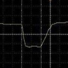
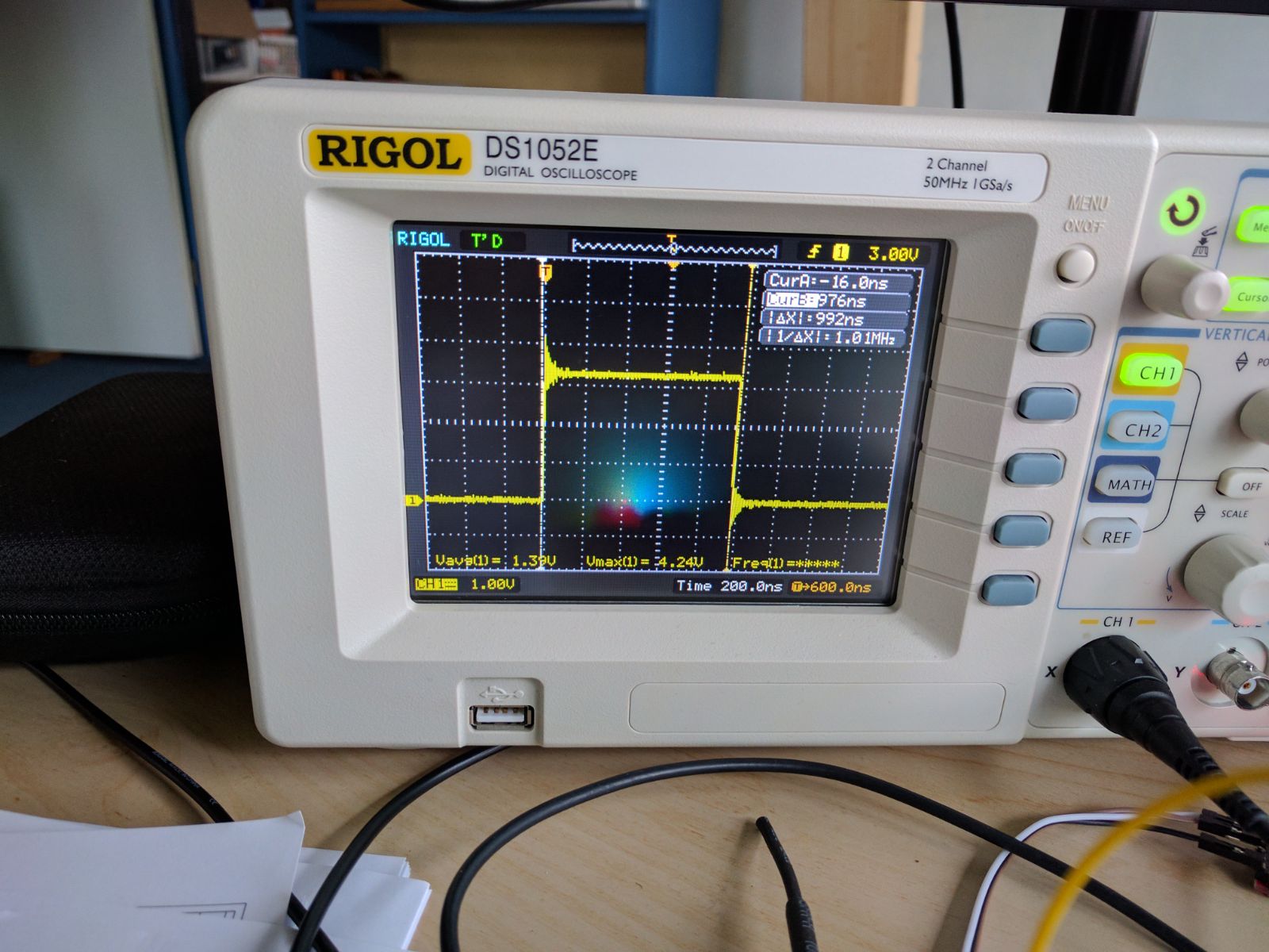
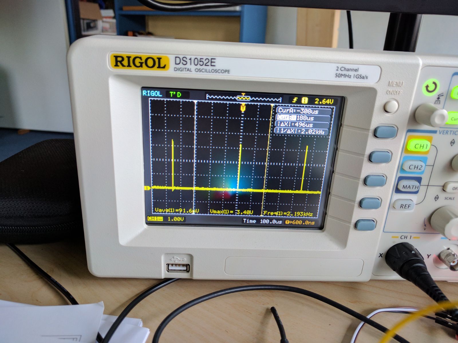
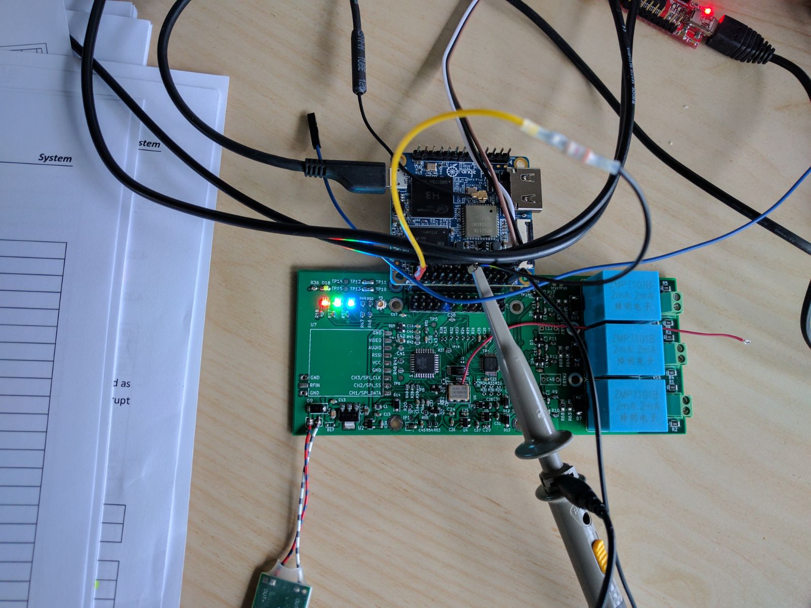
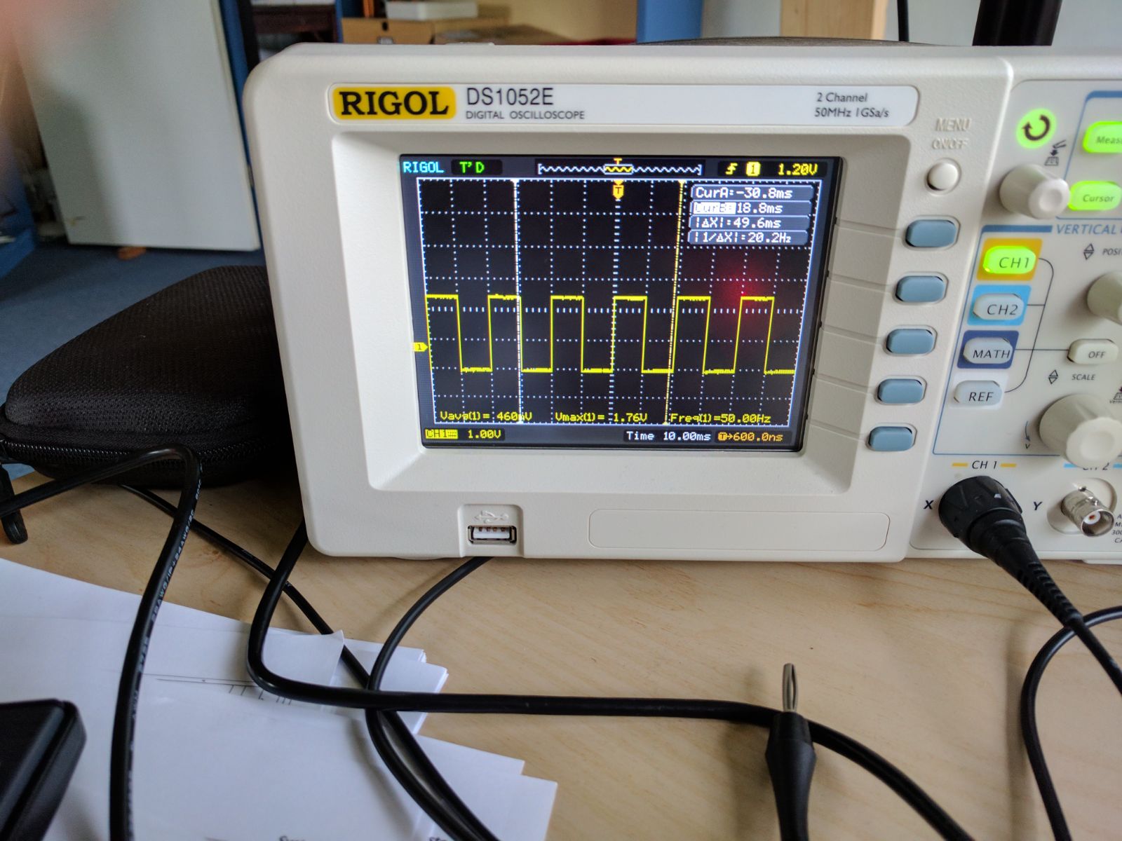
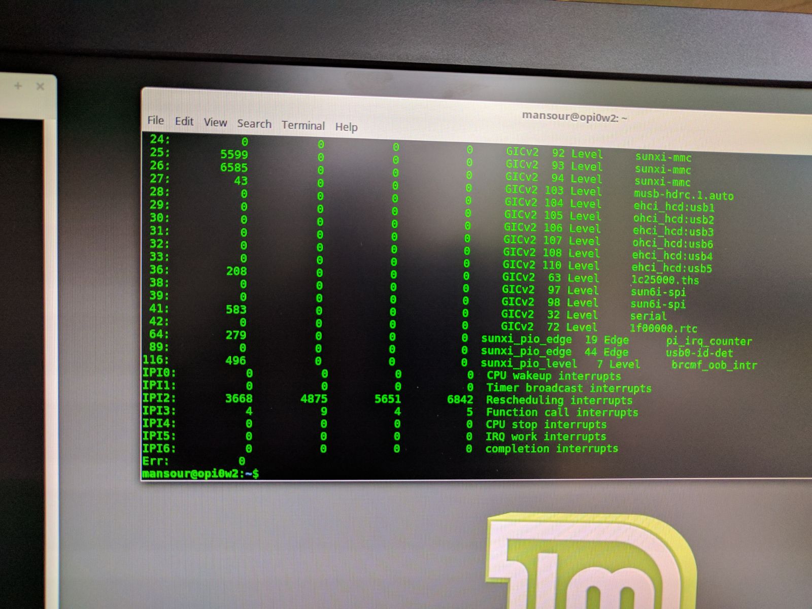
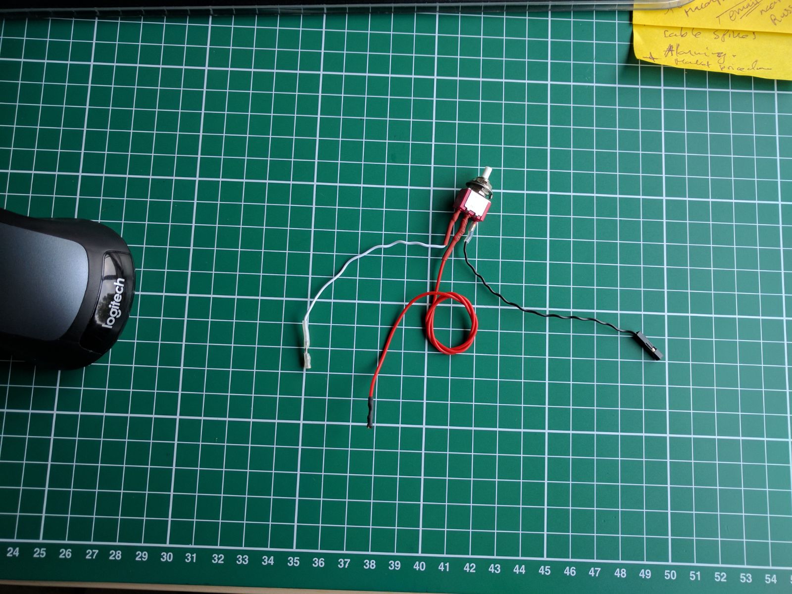
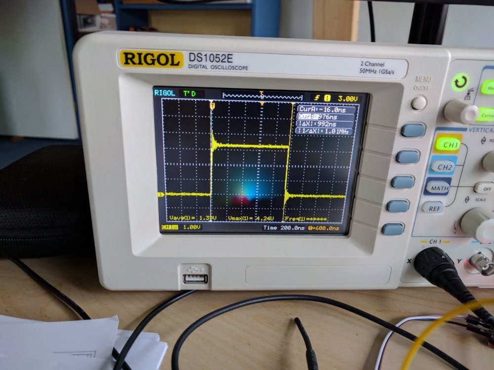
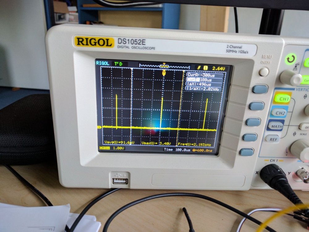
Recently i have been experimenting with interrupts on orange pi zero plus2-H3 trying to capture data-ready pulses from an external adc on gpio PA19. The aim is to synchronize spi-read-data transactions with the incoming adc data-ready signal. First I tried to get it to work on legacy kernel 3.4 by adding the following section in to /boot/script.fex and compile the .fex file to .bin file using fex2bin: [gpio_para] gpio_used = 1 gpio_num = 6 .... gpio_pin_6 = port:PA19<0><default><default><1> This configured the pin properly as i had tested on other pins with some leds and it works. The driver code for capturing the interrupt was based on an example i found at https://github.com/tomxue/Kernel_GPIO_interrupt/blob/master/m_test.c and is as follows: ... #define GPIO_PIN 19 #define GPIO_PIN_DESC "GPIO PA19 interrupt test" static irqreturn_t r_irq_handler(int irq, void *dev_id, struct pt_regs *regs) { unsigned long flags; local_irq_save(flags); printk("Interrupt [%d] on device [%s] was triggered!!\n", irq, (char *) dev_id); local_irq_restore(flags); return IRQ_HANDLED; } void config_interrupt (void) { int err; int gpio_irq; err = setup_pinmux(); if (err < 0) { printk("GPIO setup pinmux failure: %s\n", GPIO_PIN_DESC); return; } if (gpio_request(GPIO_PIN, GPIO_PIN_DESC)) { printk("GPIO request failure: %s\n", GPIO_PIN_DESC); return; } if (gpio_direction_input(GPIO_PIN)) { printk("GPIO set direction input failure %s\n", GPIO_PIN_DESC); return; } if ( (gpio_irq = gpio_to_irq(GPIO_PIN)) < 0 ) { printk("GPIO to IRQ mapping failure %s\n", GPIO_PIN_DESC); return; } printk(KERN_NOTICE "Mapped int %d\n", gpio_irq); if (request_irq(gpio_irq, (irq_handler_t ) r_irq_handler, IRQF_TRIGGER_RISING, // IRQF_TRIGGER_LOW, GPIO_PIN_DESC, GPIO_PIN_DEVICE_DESC)) { printk("Irq Request failure\n"); return; } return; } Unfortunately i could only get it to work if i replace IRQF_TRIGGER_RISING with IRQF_TRIGGER_LOW. This was tested by issuing dmesg to obtain the irq number and then cat /proc/interrupts to monitor interrupt events on the allocated irq. At first, this gave me the impression that interrupts in the kernel are polling the pin instead of actual hardware triggering. Based on the data sheets of the sunxi H3 chipset (http://dl.linux-sunxi.org/H3/Allwinner_H3_Datasheet_V1.0.pdf, page 74) PA19 is interrupt capable by the setting the pinmux to PA_EINT19, function code 0x6. So i decided to do low level configuration of the pinmux by adding the following section to the module and test accordingly: /** * Low level configuration of GPIO pin mode */ #ifdef KERNEL_34 #define IOMEM(x) ((void __force __iomem *)(x)) #ifndef IO_ADDRESS #define IO_ADDRESS(x) ((x) + 0xf0000000) #endif #ifndef __io_address #define __io_address(n) IOMEM(IO_ADDRESS(n)) #endif // IO memory map base address, discovered by searching through Armbian sources #define SUNXI_IOMEM(n) (0xf0000000 + (n)) #define PIO_BASE SUNXI_IOMEM(0x01C20800) // gpio banks of the ALLWINNER H3 #define GPIO_BANK_A 0 //#define GPIO_BANK_B 1 // not a valid bank on H3 #define GPIO_BANK_C 2 #define GPIO_BANK_D 3 #define GPIO_BANK_E 4 #define GPIO_BANK_F 5 #define GPIO_BANK_G 6 // PORT configuration registers #define Pn_CFG0_REG(n) (PIO_BASE + (n*0x24) + (0x00)) // 32bits[0..31] see data sheet #define Pn_CFG1_REG(n) (PIO_BASE + (n*0x24) + (0x04)) #define Pn_CFG2_REG(n) (PIO_BASE + (n*0x24) + (0x08)) #define Pn_CFG3_REG(n) (PIO_BASE + (n*0x24) + (0x0c)) #define PA_DAT (PIO_BASE + 0x10) #define PA_PULL (PIO_BASE + 0x1C) #define PA_EINT_CFG_REG(n) (PIO_BASE + 0x200 + (4*n)) #define PA_EINT_CTL_REG (PIO_BASE + 0x210) #define PA_EINT_STATUS_REG (PIO_BASE + 0x214) #define PA_EINT_DEB_REG (PIO_BASE + 0x218) #define readb(addr) (*((volatile unsigned char *)(addr))) #define readw(addr) (*((volatile unsigned short *)(addr))) #define readl(addr) (*((volatile unsigned long *)(addr))) #define writeb(v, addr) (*((volatile unsigned char *)(addr)) = (unsigned char)(v)) #define writew(v, addr) (*((volatile unsigned short *)(addr)) = (unsigned short)(v)) #define writel(v, addr) (*((volatile unsigned long *)(addr)) = (unsigned long)(v)) #endif #ifdef KERNEL_34 static int setup_pinmux(void) { int cfg; int shift; unsigned int val = 0x6 ; // function 0x6 = PA_EINT mode unsigned int reg, mask; //writel(0x00711112, Pn_CFG2_REG(GPIO_BANK_A)); // default register value void __iomem *base = __io_address(0x01c28000); printk("GPIO: base = 0x%lx, %s \n", (long unsigned int)base, GPIO_PIN_DESC); printk("GPIO: PIO_BASE = 0x%lx, %s \n", (long unsigned int)PIO_BASE, GPIO_PIN_DESC); // display CFG registers of GPIO_BANK_A printk("GPIO: Pn_CFG0_REG(GPIO_BANK_A) = 0x%.8lx, %s \n", readl(Pn_CFG0_REG(GPIO_BANK_A)), GPIO_PIN_DESC); printk("GPIO: Pn_CFG1_REG(GPIO_BANK_A) = 0x%.8lx, %s \n", readl(Pn_CFG1_REG(GPIO_BANK_A)), GPIO_PIN_DESC); printk("GPIO: Pn_CFG2_REG(GPIO_BANK_A) = 0x%.8lx, %s \n", readl(Pn_CFG2_REG(GPIO_BANK_A)), GPIO_PIN_DESC); printk("GPIO: Pn_CFG3_REG(GPIO_BANK_A) = 0x%.8lx, %s \n", readl(Pn_CFG3_REG(GPIO_BANK_A)), GPIO_PIN_DESC); // printk("GPIO: PA_DAT = 0x%.8lx, %s \n", readl(PA_DAT), GPIO_PIN_DESC); printk("GPIO: PA_PULL = 0x%.8lx, %s \n", readl(PA_PULL), GPIO_PIN_DESC); printk("GPIO: PA_EINT_STATUS = 0x%.8lx, %s \n", readl(PA_EINT_STATUS_REG), GPIO_PIN_DESC); printk("GPIO: PA_EINT_DEB_REG = 0x%.8lx, %s \n", readl(PA_EINT_DEB_REG), GPIO_PIN_DESC); printk("GPIO: PA_EINT_CFG_REG(0) = 0x%.8lx, %s \n", readl(PA_EINT_CFG_REG(0)),GPIO_PIN_DESC); printk("GPIO: PA_EINT_CTL_REG = 0x%.8lx, %s \n", readl(PA_EINT_CTL_REG), GPIO_PIN_DESC); printk("GPIO: writing to registers, %s \n", GPIO_PIN_DESC); //set PA19_SELECT to PA_EIN19 // PAn_SELECT(GPIO_BANK_A, 19, 0x6); // bank = (19*4)/32 = 2 = PA_CFG2 // shift = (19*4)-(bank*32)/4 cfg = (GPIO_PIN * 4) / 32; shift = ((GPIO_PIN * 4) - (cfg * 32)) ; mask = ~(0x0000000f << shift); val = val << shift; printk("GPIO: cfg=%d, shift=%d, mask=0x%.8lx, %s \n", cfg, shift, mask, GPIO_PIN_DESC); switch (cfg){ case 0: reg = readl(Pn_CFG0_REG(GPIO_BANK_A)); reg &= mask; reg |= val; writel(reg, Pn_CFG0_REG(GPIO_BANK_A)); break; case 1: reg = readl(Pn_CFG1_REG(GPIO_BANK_A)); reg &= mask; reg |= val; writel(reg, Pn_CFG1_REG(GPIO_BANK_A)); break; case 2: reg = readl(Pn_CFG2_REG(GPIO_BANK_A)); reg &= mask; reg |= val; writel(reg, Pn_CFG2_REG(GPIO_BANK_A)); break; case 3: reg = readl(Pn_CFG3_REG(GPIO_BANK_A)); reg &= mask; reg |= val; writel(reg, Pn_CFG3_REG(GPIO_BANK_A)); break; } printk("GPIO: Pn_CFG0_REG(GPIO_BANK_A) = 0x%.8lx, %s \n", readl(Pn_CFG0_REG(GPIO_BANK_A)), GPIO_PIN_DESC); printk("GPIO: Pn_CFG1_REG(GPIO_BANK_A) = 0x%.8lx, %s \n", readl(Pn_CFG1_REG(GPIO_BANK_A)), GPIO_PIN_DESC); printk("GPIO: Pn_CFG2_REG(GPIO_BANK_A) = 0x%.8lx, %s \n", readl(Pn_CFG2_REG(GPIO_BANK_A)), GPIO_PIN_DESC); printk("GPIO: Pn_CFG3_REG(GPIO_BANK_A) = 0x%.8lx, %s \n", readl(Pn_CFG3_REG(GPIO_BANK_A)), GPIO_PIN_DESC); the // enable interrupt on PA19 reg = readl(PA_EINT_CTL_REG); reg |= 1 << GPIO_PIN; writel(reg, PA_EINT_CTL_REG); printk("GPIO: PA_EINT_CTL_REG = 0x%.8lx, %s \n", readl(PA_EINT_CTL_REG), GPIO_PIN_DESC); printk("GPIO: PA_EINT_STATUS = 0x%.8lx, %s \n", readl(PA_EINT_STATUS_REG), GPIO_PIN_DESC); return 0; } #endif I could see in the dmesg printouts that the PA19-pin was configured properly but still i could only get interrupts to work if i use IRQF_TRIGGER_LOW. After some reading on the Internet and instability issues with WiFi i decided to go with the latest mainline development kernel which uses device trees. Executing the kernel module with low-level register programming on the mainline kernel resulted in Kernel-oops and segmentation faults. I modified /boot/dtb/sun8i-h3-orangepi-zeroplus.dts based on an example i found at http://geek-mag.com/posts/265668/ as follows and tested using the pulse-counter module presented at the same site: /dts-v1/; / { interrupt-parent = <0x1>; #address-cells = <0x1>; #size-cells = <0x1>; model = "Xunlong Orange Pi Zero Plus"; compatible = "xunlong,orangepi-zeroplus", "allwinner,sun8i-h3"; sst: pulse_counter { compatible = "gpio-pulse-counter"; pi_irq_counter@0 { label = "sst_PA19_pulse_counter"; pinctrl-names = "default"; pinctrl-0 = <&ext_counter_PA19>; /* bank: 0, pin 19, function 6 */ gpios = <&pio 0 19 6>; /* interrupt properties may be omitted if used gpios property */ interrupt-parent = <&pio>; interrupt-names = "counter-edge-rising"; interrupts = <19 0>; /* PA19 / EINT19 / rising edge*/ }; }; .... pio: pinctrl@01c20800 { reg = <0x1c20800 0x400>; interrupts = <0x0 0xb 0x4 0x0 0x11 0x4>; clocks = <0x2 0x36 0x3 0x5>; clock-names = "apb", "hosc", "losc"; gpio-controller; #gpio-cells = <0x3>; interrupt-controller; #interrupt-cells = <0x3>; compatible = "allwinner,sun8i-h3-pinctrl"; linux,phandle = <0xd>; phandle = <0xd>; .... ext_counter_PA19: sst_pins@0 { allwinner,pins = "PA19"; allwinner,function = "gpio_in"; drive = <0>; pull = <1>; }; }; }; Still the same issues, I could only get interrupts if i set IRQF_TRIGGER_LOW. After three weeks of reading, digging and diving on the Internet i had decided to test gpio-PA19 using a switch connected with a pull-up resistor to 3.3v. pressing the switch will result in grounding PA19 and hence a rising edge pulse will be generated when the switch is released. To my surprise i got rising edge interrupts to work. Now y thaughts are shifting towards hardware issues so i grabbed a scope and function generator to monitor the activities on the gpio-pin PA19. Here are some of my findings: Picture 1: adc_drdy_pulse_width.jpeg, pulse width 1us, frequency 2KHz - 128Khz depending on sampling frequency setup, no-interrupts detected Picture 2: adc-pulse-frequency.jpeg Picture 3: function-generator-pulse-50percent-duty.jpeg, frequency 50Hz, interrupts visible if i increase generator voltage to 4.3 volts. It seems that the gpio input load reduces the function-generator voltage from 3.3V to 2.7V and hence logic level voltages are not detected correctly. Conclusions: interrupt activity detection is lowered as the frequency increases @10KHz no more interrupts visible @1% pulse duty cycle of 400Hz no more interrupts visible Questions: 1) How do i activate hardware irq sampling on PA19 in mainline kernel? 2) How do i set irq-pin sampling debounce to 24MHz on mainline kernel? 3) Can the kernel handle high speed irq's 4) Why does are irqs not triggering when i increase the pulse frequency or lower pwm duty. 5) How can i do low level register programming in mainline kernel? Any help would be appreciated


-
I tried to build the armbian on my Orange Pi Zero Plus 2 to work on my astro project. I'm planning to connect the board to the camera module, which I'd assemble with a small scope (120mm focal length), and with a small TFT screen to make it a electronic finder scope. When I build and install the stretch server I've encounter several instability. There were some random crashes and finally I was able to get it stable. I'd like to share it here in case anyone is encountering the same. Here's the info: First I was experiencing random crashes and the exception message shows there's a problem at the high resolution timer. I simply disable the hr timer on the build. That solved the problem. Then I still experiencing random crashes, saying "Insufficient stack space to handle exception". Appearing the default stack of 8Mb was not enough. I make it 16Mb and now it's running stable. Tried running stress for 1 hr and the board is still running fine. So appearing everything is stable now. And I struggle a little bit to make the spidev & tft driver to work with the OrangePi. Here's a very useful guide here: http://eessential.blogspot.hk/2017/12/18-128-x-160-tft-lcd.html?m=1 Description: Debian GNU/Linux 9.3 (stretch) Release: 9.3 Codename: stretch Kernel: 4.14.18
-
It seems that the latest Nano Pi Neo Air Boards and the relatively new Orange Pi Zero Plus 2 both use a modified version of the AP6212 WiFi+Bluetooth module, which is physically labelled as AP6212A. This new module apparently requires different drivers to operate. From my own experience, I was unable to get the internal WiFi module to work on a Nano Pi Neo Air (with AP6212A) using any of the Armbian distributions. However, I was able to get WiFi to work on that board with the Friendly Arm distribution at from https://www.mediafire.com/folder/sr5d0qpz774cs/NanoPi-NEO_Air#oc15bwqbuxgxe. I just received a second Nano Pi Neo Air from a different vendor, and this one was apparently one of the older boards because it came without a wifi antenna, and the WiFi module was labeled AP6212. The internal WiFi on this board worked perfectly with the legacy Armbian distribution for the Nano Pi Neo Air. I've seen elsewhere that there has been some trouble getting WiFi to work with the Orange Pi Zero Plus 2, and I suspect it is because of the change in the WiFi module. I personally know nothing of how to change or compile WiFi drivers, but would comparing the drivers in the Friendly Arm distribution help?
-
Hi, I would like to share an issue concerning the OPI Zero 2+ with the camera module. I was not able to work with it and I got usual error : [ISP] isp platform_id = 5! [CSI_ERR][GC2035]sensor_read err at sensor_detect! [CSI_ERR][GC2035]chip found is not an target chip. I finally found that the FEX was incorrect. On line 384, the port definition was wrong and should be PA08 : vip_dev0_power_en = port:PA08<1><default><default><default> Then the camera is recognized : [ 8652.370168] [ISP] isp platform_id = 5! [ 8652.447812] [CSI][GC2035]V4L2_IDENT_SENSOR=2035[CSI][GC2035]disalbe oe! And worked properly with fswebcam : fswebcam -r 1600x1200 -p YUV420P - > cam1600x1200.jpg Maybe someone can tell me where to report the bug ? Hope my post may help. I attached the corrected FEX file (note that I did not check other parameters). Use fex2bin to create script.bin and put it in /boot. script.fex
-
I run into problems trying to get application distributed via snaps installed. Mount snap "core" (3751) [ 1691.207676] squashfs: SQUASHFS error: Filesystem uses "xz" compression. This is not supported error: cannot perform the following tasks: - Mount snap "core" (3751) ([start snap-core-3751.mount] failed with exit status 1: Job for snap-core-3751.mount failed. See "systemctl status snap-core-3751.mount" and "journalctl -xe" for details. Found out kernel module would need to enable CONFIG_SQUASHFS_XZ. Could someone help me by adding the module to Kernel or support me in doing so or with a much appreciated workaround. Thanks!
-
A couple of weeks ago I took delivery of an Orange Pi Zero Plus 2 H3 it has the form factor I wanted, eMMC support and HDMI which implied I could run a desktop; the H3 was also the variant that seemed to have the best support. Since then I have been trying to get a stable usable desktop environment working. I tried the latest version of Armbian legacy server specifically for this board and that works fine as far as the server version goes so then I tried to add a basic desktop but that didn't work the xOrg driver said there were no screens present and everything I tried after going to Google University failed. Then I tried a couple of distros from the Orange Pi website but none of them were really usable. Next I returned to Armbian and tried the legacy desktop image for an Orange Pi Lite and the desktop worked but obviously the AP62612 and the eMMC were not found. Finally I tried the desktop image for the Orange Pi PC Plus. The desktop works well and I can copy the image to eMMC using the Armbian script but still the AP6212 could not be initialized. Finally I tried a Realtek USB/Ethernet dongle with this image and it worked "out of the box" all I had to do was put in my SSID & WPA password. That is the setup I am working with now, but I really would like an Armbian desktop image for this board. Actually don't care if it is H3 or H5 and also don't care if it is legacy or mainline; so the simple question is are there any plan to release a desktop image for the Zero +2 or does anyone know how to install a simple desktop on top of the Armbian legacy server image? One other observation with the current arrangement the eMMC seems slower than the MicroSD I originally copied the image to but I suspect (hope) this is because I I am not using the correct image for this board. Thanks in advance. BTW you may have gathered I am not a Linux guru and think that recompiling kernels is a bit beyond my capabilities at the moment. Horty