Search the Community
Showing results for tags 'tutorial'.
-
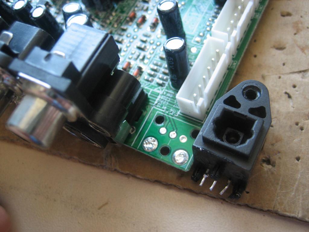
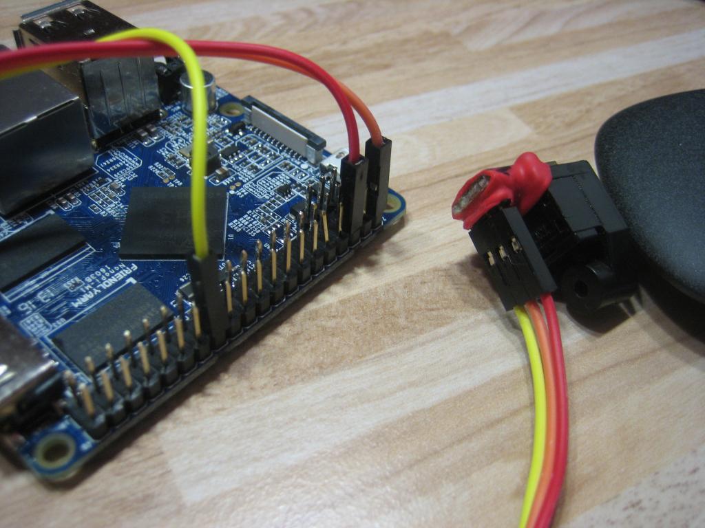
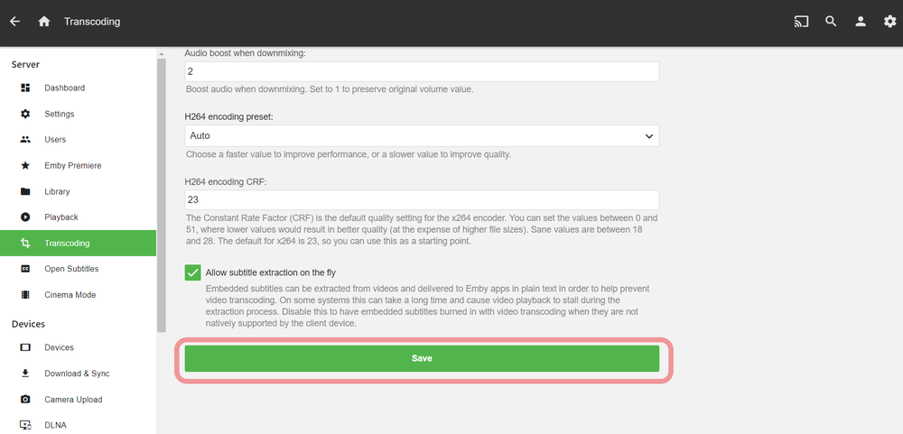
 As a result of all the work that Armbian developers put into the upgrade to kernel 4.14 for the XU4 board family, now we can enjoy many new features. One of them is the access to the SoC video encoding capabilities. Emby Media Server can take advantage of the Exynos 5422 MFC video engine for transcoding. That means lower CPU usage, lower temperatures, and the possibility of encoding in real time higher resolutions or more simultaneous streams. In my tests, I've been able to transcode one HEVC 1080p and one 480p at the same time, or five 480p (though it will depend on the bitrate of the source material). However, the ffmpeg version shipped with official Emby is quite unstable when using this feature. For that reason, I compiled a better and more stable version from @memeka's repo. I've been using it for over a month without a single crash. So this is a step-by step guide on how to make everything work: 0. [PREREQUISITE]: You must be running an Armbian Strech XU4 "Next" image, like the one you can download here. >> DOWNLOAD the emby and ffmpeg packages from this link << Install them (Note: this will install Emby Server version 3.5.3, which is the last at the writing of this tutorial. It has been tested to work with this version, and may or may not work with any other): $ tar xvf emby-server-stretch-xu4_1.0.tar.xz $ sudo dpkg -i ffmpeg/*.deb $ sudo dpkg -i emby-server/*.deb $ sudo apt -f install Hold the ffmpeg packages, so they don't get upgraded: $ sudo apt-mark hold ffmpeg-doc ffmpeg libavcodec-dev libavcodec-extra libavdevice-dev libavfilter-dev libavfilter-extra libavformat-dev libavresample-dev libavutil-dev libmysofa-dev libmysofa-utils libmysofa0 libpostproc-dev libswresample-dev libswscale-dev Add the user "emby" to the video group, so it can have access to the transcoding engine: $ sudo usermod -aG video emby Modify the emby executable, to use our custom ffmpeg (Note: you will need to repeat this step every time you update the emby deb package): $ sudo nano /opt/emby-server/bin/emby-server # Change the following line: ffmpeg $APP_DIR/bin/ffmpeg \ # to: ffmpeg /usr/bin/ffmpeg \ Restart the service: $ sudo service emby-server restart Now, you can open the web browser, point to your Emby server (e.g. http://odroidxu4.local:8096), and configure it as described in the official tutorial (https://github.com/MediaBrowser/Wiki/wiki/Installation). For last, you need to enable Hardware video transcoding in the web interface. The option is under the "Transcoding" submenu. Don't forget to click on "Save" when you are done: And that's it! As an additional tip, I recommend disabling UPnP in Emby, because it causes the program to crash frequently when enabled (this is just a general recommendation, it has nothing to do with hardware encoding). Enjoy! And please, share your experiences and comments here.
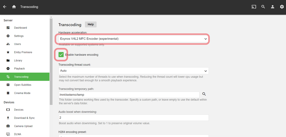
-
 There is no official sdcard image but the attached script will create a image for the OrangePi Zero/R1. It uses daily generated files from Debian daily-images and considered testing/unstable. SDcard image creation: You will need basic Linux/Debian and dosfs utils. No su/root needed. Run the script to generate sdcard image for writing to sdcard. Optionally, if you want ssh network-console access, add preseed.cfg to same directory as script. See attached preseed.cfg and example-preseed.txt . Basic installation: Once the installer is started, it runs completely in RAM and no longer needs files from the sdcard. You can delete all partitions on the sdcard and install Debian. Guided partitioning is recommended. When using ssh network-console installer, allow time for the installer to download files before logging in using ssh installer@IPAddress. Basic SDcard image script guide: Two parts are needed, the device-specific firmware.img.gz and partition.img.gz. Concatenate both to get full sdcard image. There is no firmware for the Zero/R1 but can easily be created by using gen-hd-image and extracted u-boot binary from deb file. For more info, see attached opz-sd-gen.sh script and wiki.debian.org. Notice: Posted for anyone interested in testing and experimental purposes. opz-sd-gen.sh preseed.cfg Edit: To use buster u-boot version instead of stretch, edit script with: sed -i 's/^UBOOTDEB.*/UBOOTDEB="u-boot-sunxi_2018.05+dfsg-1_armhf.deb"/' opz-sd-gen.sh
 -
hi all, as documented here, i did some minor experiments with small heatsinks on an orange pi one sbc (allwinner H3) among the things i used a small matrix multiplication program which multiplies a 1000x1000 matrix single precision floating point matrix main.cpp the command to build is c++ -O2 -std=gnu++11 -pthread -o mat main.cpp then run ./mat the last documented results on an orange pi one H3 running at 1.2ghz is 2389.49Mflops ~ 2.39Gflops the sources attached is 'optimised', the means of optimization is unrolling of the innermost loop to take advantage of platforms that could do quad sp fp simultaneous execute i think those neon enabled platforms would be able to do that. the other optimization is that it spawn off 4 threads so that it could utilise 4 simultaneous threads for the matrix multiplication could try to run this and let us know what is the 'mflops' you get on your sbc? what is the sbc , the soc and the frequency it is running at? note that this is not necessarily the most optimised for your sbc / soc the parameters you could try to tune includes the THREADS_NUMBER for the number of concurrent threads in the source code in addition those who have more powerful soc could try to unroll the loops further, e.g. try to compile with additional options like -funroll-loops or even -funroll-all-loops you could also manually update the codes e.g. to double the set of manually unrolled codes in the loop so that it become 8 sets of computations instead of 4, but you would need to review the codes such as using MATRIX_SIZE/8; i+= 8 in in the loop if you unroll the loop into 8 sets of variables, you'd need to update the summation after the loop as well result.elements[row][col] = r1+r2+r3+r4; to add the other r variables that you unrolled into the original 'unoptimised' codes can be found in references in the original post. strictly speaking this is not really a good test of computational prowess unlike those of linpack etc. linpack actually solves a matrix, and this is purely a square matrix multiply. in addition, this does not explicitly use neon etc and those usage depends on the compiler optimization (i think gcc / g++ has a build in vectorizer, hence you may like to experiment with the options) but nevertheless seeing mflops, gflops is fun, mflops, gflops is also normally a function of the frequency the core executes at, hence you could try to overclock your soc to get more gflops
-
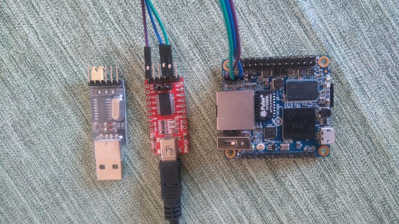
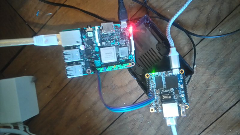
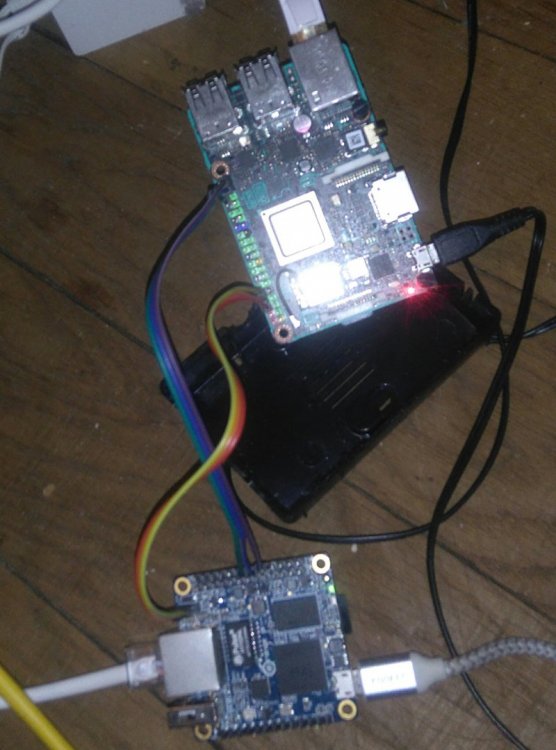
 Access to a console can be mandatory when you SBC doesn't work as expected (e.g Network or HDMI output doesn't work). When SSH/Display access isn't possible access to console via UART is the best way to get a clue where your SBC hangs. This short tutorial should give you an introduction how this works. For some boards, armbian implements an USB gadget mode (a 'fake' serial console over microUSB) describen below. As a reminder an USB-UART bridge is always prefered over USB gadget mode whenever possible (UART get's initialized before the gadget driver and also before HDMI, means even if you don't get a proper output from HDMI or gadget mode console, it is possible that UART will give you the needed information). Prerequisites: We need an Terminal program to access the console. If you use Linux on your host system I prefer picocom (something like minicom will also do the job) which can be installed: on debian a like systems: sudo apt-get install picocom from arch community repo: https://www.archlinux.org/packages/community/x86_64/picocom/ on fedora systems: yum install picocom on Mac OS X: brew install picocom on Widows we use PuTTY: https://www.chiark.greenend.org.uk/~sgtatham/putty/latest.html UART USB Adapter: There are various USB-UART bridges e.g FT232 (and fakes of them, cause FDTI is expensive ), CH340/1,PL2303 or CP2102 Normally it doesn't matter which one you use. I prefer the (probably fake) FDTI on the right side, but the CH341 does also a good job: The only thing which is needed is that the signal-level matches with your SBCs needs (this is mostly 3.3V expect some Odroids e.g HC1 which has only 1.8V!). Most of these USB-UART bridges have jumpers for 5V and 3.3V, make sure that you use the 3.3V. You've to figure out which pins on your SBC are debug UART (they've mostly a own 3 pin header, sometimes it's on the large pin header e.g. Tinkerboard) and then connect: GND --> GND RX --> TX TX --> RX You've to check dmesg (linux) or run devmgmt.msc (windows) to know which device you use. Linux: [256597.311207] usb 3-2: Product: USB2.0-Serial [256597.402283] usbcore: registered new interface driver ch341 [256597.402341] usbserial: USB Serial support registered for ch341-uart [256597.402392] ch341 3-2:1.0: ch341-uart converter detected [256597.404012] usb 3-2: ch341-uart converter now attached to ttyUSB0 --> Device will be /dev/ttyUSB0 Windows: for windows 10 (https://www.google.ch/search?client=opera&q=find+arduino+port+windows+10&sourceid=opera&ie=UTF-8&oe=UTF-8) Something like the picture in USB Gadget Mode part of the tutorial should show up) Armbians default settings are (expect some RK devices): For Picocom: picocom -b 115200 -r -l /dev/ttyUSB0 and for some RK devices: picocom -b 1500000 -r -l /dev/ttyUSB0 For PuTTY: You've to set configuration in 'Serial'. COM11 is just an example and needs to be checked first, Speed (baud) needs to be changed when you deal with the few RK boards which need 1500000. OS X: TBD should be similar to Linux whereas the naming differs a bit. See: https://forum.odroid.com/viewtopic.php?f=53&t=841 as an example with minicom. Normally you connect the USB-UART bridge to your host computer (and the SBC) and start picocom/putty before you power the board to ensure you get the full bootlog and not only parts of it. USB Gadget Mode Several board (see list) for which official armbian images exist (or csc images can be built) have no HDMI display. On those boards there's USB gadget mode driver activated so that you can have console access to them via USB connection. The following short tutorial describes how you can access to console from Linux (don't have a windows machine here at the moment, I may check it later): install picocom connect your board via USB to your host computer (it should be one which is able to power an SBC via its USB port) check dmesg for the device showing up: [184372.603816] usb 3-2: Product: Gadget Serial v2.4 [184372.603818] usb 3-2: Manufacturer: Linux 4.14.65-sunxi with musb-hdrc [184372.660041] cdc_acm 3-2:2.0: ttyACM0: USB ACM device [184372.660402] usbcore: registered new interface driver cdc_acm [184372.660403] cdc_acm: USB Abstract Control Model driver for USB modems and ISDN adapters connect to it via picocom (in this case 'picocom /dev/ttyACM0'): chwe@chwe-acer:~$ picocom /dev/ttyACM0 picocom v2.2 port is : /dev/ttyACM0 flowcontrol : none baudrate is : 9600 parity is : none databits are : 8 stopbits are : 1 escape is : C-a local echo is : no noinit is : no noreset is : no nolock is : no send_cmd is : sz -vv receive_cmd is : rz -vv -E imap is : omap is : emap is : crcrlf,delbs, Type [C-a] [C-h] to see available commands Terminal ready Debian GNU/Linux 9 orangepizero ttyGS0 orangepizero login: root Password: You are required to change your password immediately (root enforced) Changing password for root. (current) UNIX password: I assume if you use the same settings in something like putty on windows and you check which 'serial' device shows up in *where windows shows connected devices - I forgot it* you should be able to access it from windows (someone motivated may confirm this). For Windows: run devmgmt.msc and search for the serial device (in this case COM3) and connect to it via PuTTY (thanks to @hjc): for windows 10 (https://www.google.ch/search?client=opera&q=find+arduino+port+windows+10&sourceid=opera&ie=UTF-8&oe=UTF-8): (even the tutorial is for arduinos, it should be similar for every 'COM device') Currently boards with USB gadget mode: bananapim2plus bananapim2zero nanopifire3 nanopim3 nanopineo2 nanopineocore2 nanopineoplus2 orangepizeroplus nanopiair nanopiduo nanopineo olimex-som204-a20 orangepilite orangepi-r1 orangepizero orangepizeroplus2-h3 orangepizeroplus2-h5 tritium-h3 The silly approach For those, who want to save 1$ for an USB-UART bridge, you can spend 10$ for an OrangePi Zero and use its spare UARTs to log into an other SBC... SSH --> opi, ttl --> Tinkerboard For those loving text more than videos: SSH to your SBC sudo armbian-config --> system --> hardware to activate an spare UART (in this case it was UART2, will give you ttyS2) reboot picocom -b 115200 -r -l /dev/ttyS2 See: https://asciinema.org/a/B87EOGhc0gx9oikMAGEG94lXR
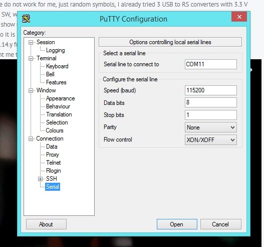
-
 (disclaimer) No itention to make a Frankendebian (https://wiki.debian.org/DontBreakDebian) but ubuntu package "zram-config" works perfectly. I tested it for two weeks in a: Orange PI Zero 512MB Armbian Stretch 5.40 4.14.18, Orange PI PC2 Armbian Stretch 5.40 4.14.18, AMD Sempron microserver Debian Stretch 9.4 4.9.0-6-amd64. A short tutorial: 1. Download zram-config package (it's a universal package, it does not matter the architecture in use) wget http://de.archive.ubuntu.com/ubuntu/pool/universe/z/zram-config/zram-config_0.5_all.deb 2. Install it sudo dpkg -i zram-config_0.5_all.deb 3. Remove the installer rm zram-config_0.5_all.deb 4. Check vm.swappiness cat /proc/sys/vm/swappiness (must be 60, default) 5. If not (i.e. "cat /proc/sys/vm/swappiness" return "1" ) change it to "60" sudo nano /etc/sysctl.conf and add "vm.swappiness=60" at the end of file ... and reboot 6. check zRAM service sudo zramctl NAME ALGORITHM DISKSIZE DATA COMPR TOTAL STREAMS MOUNTPOINT /dev/zram0 lzo 437,8M 5,2M 1,4M 1,9M 2 [SWAP] /dev/zram1 lzo 437,8M 5,2M 1,4M 1,9M 2 [SWAP] 7. (optional) change lzo compression to lz4 sudo nano /usr/bin/init-zram-swapping # initialize the devices for i in $(seq ${NRDEVICES}); do DEVNUMBER=$((i - 1)) echo $mem > /sys/block/zram${DEVNUMBER}/disksize mkswap /dev/zram${DEVNUMBER} swapon -p 5 /dev/zram${DEVNUMBER} done to... # initialize the devices for i in $(seq ${NRDEVICES}); do DEVNUMBER=$((i - 1)) echo lz4 > /sys/block/zram${DEVNUMBER}/comp_algorithm echo $mem > /sys/block/zram${DEVNUMBER}/disksize mkswap /dev/zram${DEVNUMBER} swapon -p 5 /dev/zram${DEVNUMBER} done 8. restart the service sudo systemctl restart zram-config.service 9. check new compression algorithm sudo zramctl NAME ALGORITHM DISKSIZE DATA COMPR TOTAL STREAMS MOUNTPOINT /dev/zram0 lz4 437,8M 5,2M 1,4M 1,9M 2 [SWAP] /dev/zram1 lz4 437,8M 5,2M 1,4M 1,9M 2 [SWAP] 10. check the zRAM priority over file swap cat /proc/swaps zRAM devices must be at priority "5", swap file at "-1" or "-2" 11. finish :-)
 -
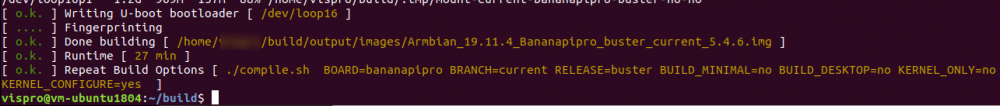
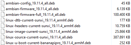
 EDIT: 04.01.2020 - Fixed patches to work with latest armbian sources. (references have changed) Hi everybody, Here is a tutorial to enable the Lemaker 7" Touchscreen on BananaPi Pro with Debian Buster and Mainline-Kernel 5.XX.XX. Kernel: Mainline 5.4.6 / Buster Board: BananaPi Pro WebLinks: • https://forum.armbian.com/topic/1905-enabling-lcd-in-u-boot-kernel-472/ • https://forum.armbian.com/topic/1849-touch-driver-banana-pi/ • http://www.atakansarioglu.com/getting-started-bananapi-linux/ • http://forum.lemaker.org/thread-15482-1-1.html • http://linux-sunxi.org/LCD To make the 7"LCD and the Touchscreen working with BananaPi Pro we need to patch some files and change the kernel config to build the driver for the touchscreen. To do this we need a working setup of the Armbian build tool chain (https://docs.armbian.com/Developer-Guide_Build-Preparation/) /home/<USER>/build/cache/sources/u-boot/v201X.XX/configs/Bananapro_defconfig /home/<USER>/build/cache/sources/u-boot/v201X.XX/arch/arm/dts/sun7i-a20-bananapro.dts /home/<USER>/build/cache/sources/linux-mainline/linux-4.XX.y/arch/arm/boot/dts/sun7i-a20-bananapro.dts 1. U-Boot ( u-boot version that supports the LCD - must be compiled) Start the build process with ./compile.sh CREATE_PATCHES=yes When asked for: [ warn ] Applying existing u-boot patch [ /home/[USER]/build/output/patch/u-boot-sunxi-current.patch ] [ warn ] Make your changes in this directory: [ /home/[USER]/build/cache/sources/u-boot/v201X.XX ] [ warn ] Press <Enter> after you are done [ waiting ] a) edit /home/<USER>/build/cache/sources/u-boot/v201X.XX/configs/Bananapro_defconfig add the following: #7" LVDS LCD CONFIG_VIDEO_LCD_MODE="x:1024,y:600,depth:24,pclk_khz:55000,le:100,ri:170,up:10,lo:15,hs:50,vs:10,sync:3,vmode:0" CONFIG_VIDEO_LCD_PANEL_LVDS=y CONFIG_VIDEO_LCD_POWER="PH12" CONFIG_VIDEO_LCD_BL_EN="PH8" CONFIG_VIDEO_LCD_BL_PWM="PB2" b) edit /home/<user>/build/cache/sources/u-boot/v201X.XX/arch/arm/dts/sun7i-a20-bananapro.dts add after: &i2c2 { ... }; the following: &i2c3 { status = "okay"; pinctrl-names = "default"; pinctrl-0 = <&i2c3_pins>; edt: edt-ft5x06@38 { compatible = "edt,edt-ft5x06", "edt,edt-ft5206"; reg = <0x38>; pinctrl-names = "default"; pinctrl-0 = <&edt_ft5x06_pins_a &edt_ft5x06_pins_b>; interrupt-parent = <&pio>; interrupts = <7 9 IRQ_TYPE_EDGE_FALLING>; touchscreen-size-x = <1024>; touchscreen-size-y = <600>; }; }; Add these two new sections to the end of the file: &pio { edt_ft5x06_pins_a: ft5@0 { pins = "PH9"; function = "irq"; drive-strength = <20>; bias-pull-up; }; edt_ft5x06_pins_b: ft5@1 { pins = "PH7"; function = "gpio_out"; drive-strength = <20>; bias-pull-up; output-high; }; }; &pwm { pinctrl-names = "default"; pinctrl-0 = <&pwm0_pin>, <&pwm1_pin>; status = "okay"; }; Then save and press <Enter> to continue. 2. Kernel patches - DTB (Device Tree Blob) file that fits to your Kernel and supports pwm When asked for: [ warn ] Applying existing kernel patch [ /home/<USER>/build/output/patch/kernel-sunxi-current.patch ] [ warn ] Make your changes in this directory: [ /home/<USER>/build/cache/sources/linux-mainline/orange-pi-5.XX ] [ warn ] Press <Enter> after you are done [ waiting ] c) edit /home/<USER>/build/cache/sources/linux-mainline/orange-pi-5.XX/arch/arm/boot/dts/sun7i-a20-bananapro.dts add the same lines like section b) Then save and press <Enter> to continue. 3. Compile Touchdriver menuconfig > Device Drivers > Input Device Support > Touchscreens > EDT FocalTech FT5x06 I2C Touchscreen support Exit and save the Kernel configuration. This is the outcome. You probably have a newer version than 19.11.4: Now you can flash the image to a SD-Card or you have to install the new DEBs. dpkg -i linux-u-boot-current-bananapipro_19.11.4_armhf.deb dpkg -i linux-dtb-current-sunxi_19.11.4_armhf.deb dpkg -i linux-image-current-sunxi_19.11.4_armhf.deb reboot The result: The LCD and the touchscreen are working. Attention! There is still the problem with the shutdown. When the patches were made for the LCD, the board did not shut down completely during a shutdown (LCD still had voltage and the red LED on the board did not go out). Workaround: We need to disable the LCD before the shutdown is finished. Therfore we have to create a script in the folder /lib/systemd/system-shutdown e.g. (as root) touch /lib/systemd/system-shutdown/lcd_off.sh chmod +x /lib/systemd/system-shutdown/lcd_off.sh nano /lib/systemd/system-shutdown/lcd_off.sh add these lines: #!/bin/bash # LCD Power PH12 H=8 (8-1)*32+12 = 236 # Backlight enable PH8 H=8 (8-1)*32+8 = 232 # Backlight PWM PB2 B=2 (2-1)*32+2 = 34 if [ ! -d "/sys/class/gpio/gpio34" ] then sudo sh -c 'echo "34" > /sys/class/gpio/export' sudo sh -c 'echo "out" > /sys/class/gpio/gpio34/direction' sudo sh -c 'echo "1" > /sys/class/gpio/gpio34/value' fi if [ ! -d "/sys/class/gpio/gpio232" ] then sudo sh -c 'echo "232" > /sys/class/gpio/export' sudo sh -c 'echo "out" > /sys/class/gpio/gpio232/direction' sudo sh -c 'echo "1" > /sys/class/gpio/gpio232/value' fi if [ ! -d "/sys/class/gpio/gpio236" ] then sudo sh -c 'echo "236" > /sys/class/gpio/export' sudo sh -c 'echo "out" > /sys/class/gpio/gpio236/direction' sudo sh -c 'echo "1" > /sys/class/gpio/gpio236/value' fi # LCD on/off sudo sh -c 'echo "0" > /sys/class/gpio/gpio34/value' sudo sh -c 'echo "0" > /sys/class/gpio/gpio232/value' sudo sh -c 'echo "0" > /sys/class/gpio/gpio236/value' The script will be executed right before the board powers off. Measured power consumption: PowerON (booting / lcd still off) = 0.4A - 0.5A LCD turns on (still booting) = 0.85A - 1.05A Boot process ended (LCD on) = 0.75A Board on, LCD off = 0.35A - 0.45A ( -> LCD needs around 0.4A power ) shutdown -h now = 0.00A 4. Control the Power of the Backlight: The backlight PWM is on PIN CON2 PB2. Following the instructions on http://linux-sunxi.org/GPIO#Accessing_the_GPIO_pins_through_sysfs_with_mainline_kernel http://forum.lemaker.org/thread-10852-1-1.html we have to export GPIO-PIN 34. (position of letter in alphabet - 1) * 32 + pin number position of letter in alphabet: B = 2 pin number: 2 ( 2 - 1 ) * 32 + 2 = 34 echo 34 > /sys/class/gpio/export echo "out" > /sys/class/gpio/gpio34/direction Power on the Backlight: echo "1" > /sys/class/gpio/gpio34/value Power off the Backlight: echo "0" > /sys/class/gpio/gpio34/value Now we could use a switch connected to a GPIO-IN to control the backlight. Steffen
-
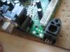
 Hi, This topic was a initially a question and become a tutorial to use push buttons on orange pi PC. This tutorial has been made with an Orange PI PC running on "Armbian_5.35_Orangepipc_Debian_jessie_default_3.4.113.img". With this example you will be able to launch 3 different scripts for each push button : /usr/local/bin/run<Wpi GPIO number>short.sh -> immediately launched when a button is pressed /usr/local/bin/run<Wpi GPIO number>long.sh -> launched after a long pression /usr/local/bin/run<Wpi GPIO number>release.sh -> launched when a button is released (but not after a long pression) I've made this image to know easily see the correspondence between WiringOP and physical Orange PI PC connector : Mhhh if you want to modify it, you'll find the excel source file here. Sources : http://orangepi.club/showthread.php?tid=2173 -> excellent tutorial for beginners ! https://github.com/zhaolei/WiringOP -> a modified WiringPi for OrangePi http://nix.zeya.org/wiki/разработка_средств_аппаратного_управления_для_orange_pi_pc -> a very good example of program in C to use Orange PI GPIO with push buttons To install and compile the WiringOP library : mkdir downloads cd downloads git clone https://github.com/zhaolei/WiringOP.git -b h3 cd WiringOP/ sudo ./build Make a test : gpio readall You should obtain something like that : +-----+-----+----------+------+---+-Orange Pi+---+---+------+---------+-----+--+ | BCM | wPi | Name | Mode | V | Physical | V | Mode | Name | wPi | BCM | +-----+-----+----------+------+---+----++----+---+------+----------+-----+-----+ | | | 3.3v | | | 1 || 2 | | | 5v | | | | 12 | 8 | SDA.0 | ALT5 | 0 | 3 || 4 | | | 5V | | | | 11 | 9 | SCL.0 | ALT5 | 0 | 5 || 6 | | | 0v | | | | 6 | 7 | GPIO.7 | ALT3 | 0 | 7 || 8 | 0 | ALT3 | TxD3 | 15 | 13 | | | | 0v | | | 9 || 10 | 0 | ALT3 | RxD3 | 16 | 14 | | 1 | 0 | RxD2 | ALT3 | 0 | 11 || 12 | 0 | ALT3 | GPIO.1 | 1 | 110 | | 0 | 2 | TxD2 | ALT3 | 1 | 13 || 14 | | | 0v | | | | 3 | 3 | CTS2 | IN | 1 | 15 || 16 | 0 | ALT3 | GPIO.4 | 4 | 68 | | | | 3.3v | | | 17 || 18 | 0 | ALT3 | GPIO.5 | 5 | 71 | | 64 | 12 | MOSI | ALT4 | 0 | 19 || 20 | | | 0v | | | | 65 | 13 | MISO | ALT4 | 0 | 21 || 22 | 0 | ALT3 | RTS2 | 6 | 2 | | 66 | 14 | SCLK | ALT4 | 0 | 23 || 24 | 0 | ALT4 | CE0 | 10 | 67 | | | | 0v | | | 25 || 26 | 0 | ALT5 | GPIO.11 | 11 | 21 | | 19 | 30 | SDA.1 | ALT5 | 0 | 27 || 28 | 0 | ALT5 | SCL.1 | 31 | 18 | | 7 | 21 | GPIO.21 | IN | 1 | 29 || 30 | | | 0v | | | | 8 | 22 | GPIO.22 | IN | 1 | 31 || 32 | 0 | ALT3 | RTS1 | 26 | 200 | | 9 | 23 | GPIO.23 | IN | 1 | 33 || 34 | | | 0v | | | | 10 | 24 | GPIO.24 | IN | 1 | 35 || 36 | 0 | ALT3 | CTS1 | 27 | 201 | | 20 | 25 | GPIO.25 | ALT5 | 0 | 37 || 38 | 0 | ALT3 | TxD1 | 28 | 198 | | | | 0v | | | 39 || 40 | 0 | ALT3 | RxD1 | 29 | 199 | +-----+-----+----------+------+---+----++----+---+------+----------+-----+-----+ | BCM | wPi | Name | Mode | V | Physical | V | Mode | Name | wPi | BCM | +-----+-----+----------+------+---+-Orange Pi+---+------+----------+-----+-----+ Now we are going to write a program in C to detects pushes on buttons : nano pushbuttons.c The copy / paste the C program below : (you should modify the numbers of buttons that you use, the WiringOP pins that you use, you can create scripts later) OK now compile it and run it : gcc -lwiringPi -lwiringPiDev -o pushbuttons pushbuttons.c ./pushbuttons Press a button and you're done FYI : To use the native button on the motherboard of the orange PI PC you can use "acpid" to make working for reboot I hope it will be useful to some of you.
-
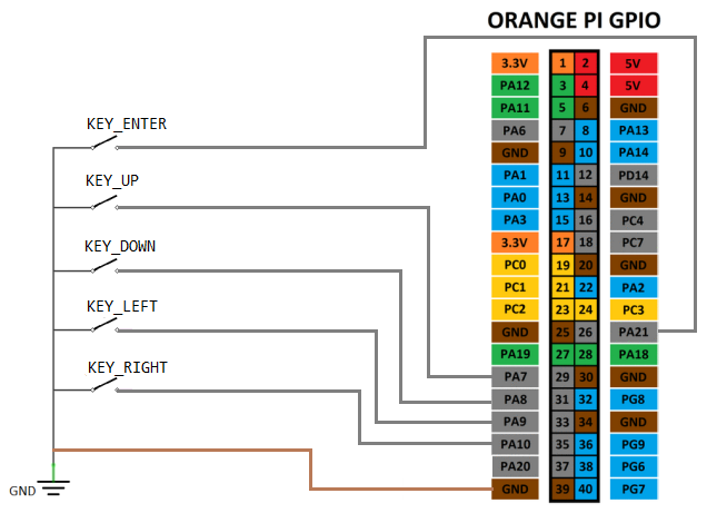
overlay examples: GPIO keys Mainline Linux OrangePi gpio-keys.dts /dts-v1/; /plugin/; / { compatible = "allwinner,sun4i-a10", "allwinner,sun7i-a20", "allwinner,sun8i-h3", "allwinner,sun50i-a64", "allwinner,sun50i-h5"; fragment@0 { target = <&pio>; __overlay__ { gpio_keys: gpio_keys { pins = "PA7","PA8","PA9","PA10","PA21"; function = "gpio_in"; bias-pull-up; }; }; }; fragment@1 { target-path = "/"; __overlay__ { gpio-keys-user { compatible = "gpio-keys"; pinctrl-names = "default"; pinctrl-0 = <&gpio_keys>; g-keys_up { label = "GPIO KEY_UP"; linux,code = <103>; /* KEY_UP, see /usr/include/linux/input-event-codes.h */ gpios = <&pio 0 7 1>; /* PA7 GPIO_ACTIVE_LOW */ }; g-keys_down { label = "GPIO KEY_DOWN"; linux,code = <108>; /* KEY_DOWN, see /usr/include/linux/input-event-codes.h */ gpios = <&pio 0 8 1>; /* PA8 GPIO_ACTIVE_LOW */ }; g-keys_left { label = "GPIO KEY_LEFT"; linux,code = <105>; /* KEY_LEFT, see /usr/include/linux/input-event-codes.h */ gpios = <&pio 0 9 1>; /* PA9 GPIO_ACTIVE_LOW */ }; g-keys_right { label = "GPIO KEY_RIGHT"; linux,code = <106>; /* KEY_RIGHT, see /usr/include/linux/input-event-codes.h */ gpios = <&pio 0 10 1>; /* PA10 GPIO_ACTIVE_LOW */ }; g-keys_enter { label = "GPIO KEY_ENTER"; linux,code = <28>; /* KEY_ENTER, see /usr/include/linux/input-event-codes.h */ gpios = <&pio 0 21 1>; /* PA21 GPIO_ACTIVE_LOW */ }; }; }; }; }; https://github.com/ua3nbw-cf/gpio-keys
-
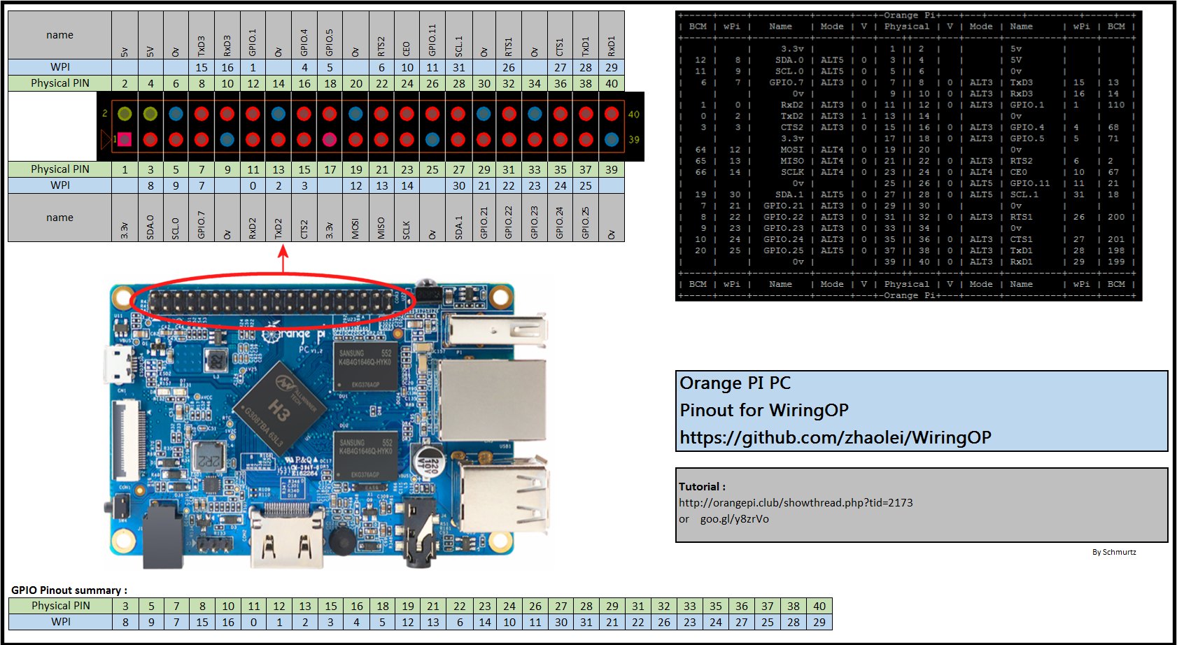
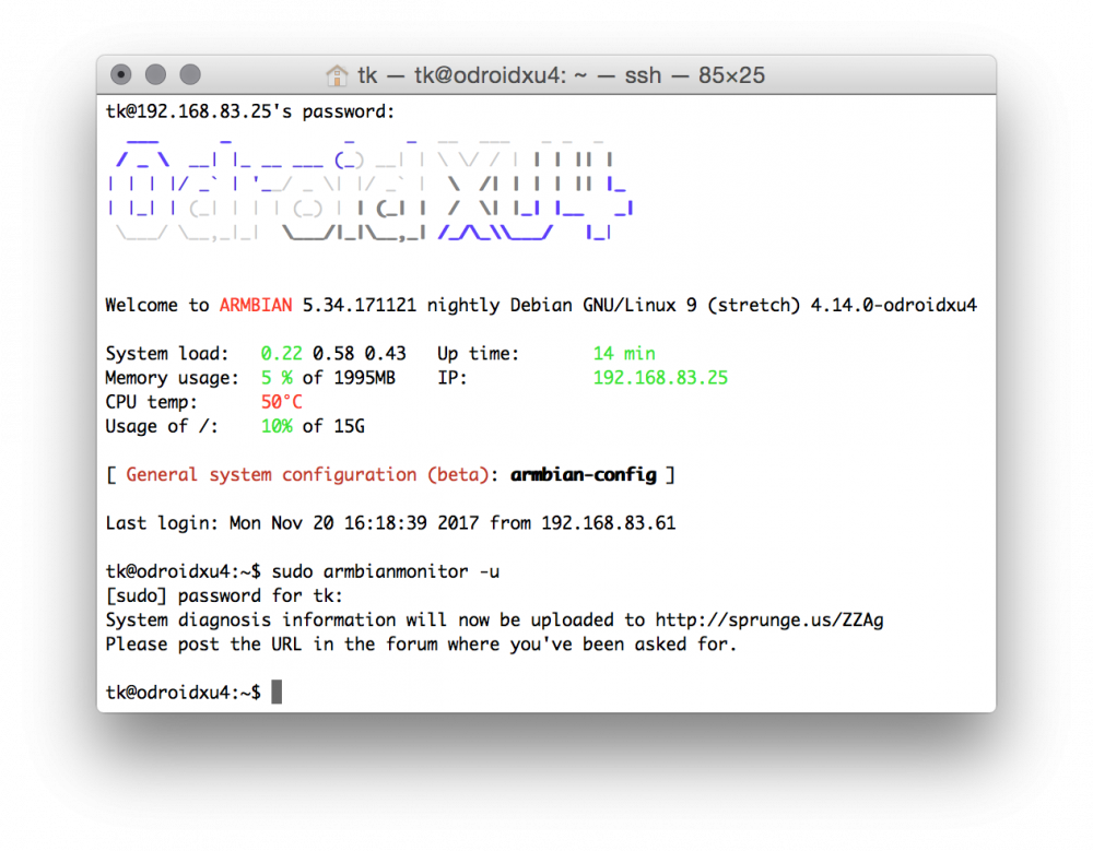
Armbian implements some basic 'system logging' at every startup and shutdown and contains a little utility to provide this collected information combined with some more useful debug info from user installations. All that's needed is executing 'sudo armbianmonitor -u' (or armbian-config --> Software --> Diagnostics) and then all this support related information is uploaded to an online pasteboard service automagically (see example output) How to interpret this wall of text? The output is best read from bottom to top since the most important information is collected during upload: At the bottom /proc/interrupts contents to check for IRQ affinity problems (interrupt collissions on some CPU cores negatively affecting performance) Then last 250 lines dmesg output are included. Here you might find important information wrt the last (kernel) events that happened on the machine uptime output including average load statistics (1, 5 and 15 min) free output telling how much physical memory is available and how much swap and/or zram is used (you need to look directly above whether zram is active or not to interpret the 'Swap:' line) vmstat output contains virtual memory usage information since last reboot iostat output contains the same but allows for a 'per device' view since all devices are listed with individual statistics (so it's easy to spot IO bottlenecks by looking at these numbers and also looking at %iowait value) 'Current system health' displays what the system is actually doing while uploading the debug log (on systems where DC-IN monitoring is available also allowing for underpowering diagnosis -- if you read here numbers below 5.0V stop reading the log and tell the user to fix his underpowering issues first) In case the installation has been moved from SD card to other storage nand-sata-install.log will be included in the output 'Loaded modules' allow to look for module related problems If it's an Allwinner board running legacy kernel the whole script.bin contents are included 'Installed packages' shows version numbers of relevant Armbian packages 'Group membership of' should list all groups the user is member of. If this line is missing ignore the whole contents and ask the user to re-submit debug info, this time doing it correctly not as root but using 'sudo armbianmonitor -u' (group memberships are important to understand certain problems, eg. users not being member of audio group won't have success getting noise out of their devices) If the board is PCIe capable list of attached PCIe devices is included The lsusb output lists all connected USB devices and also information about speed (12M, 480M, 5000M) and protocol/connection details (mass-storage vs uas for example) If the user installed the lshw utility and verbosity is set to 4 or above in /boot/armbianEnv.txt some more disk related information will be included Important: The debug output also contains all collected support files that follow this naming scheme: /tmp/armbianmonitor_checks_* -- so if a user complains about 'transmission so slow' or 'latest files are always missing' ask him to run 'armbianmonitor -c /path/to/torrent-storage' and afterwards 'sudo armbianmonitor -u' without a reboot in between since then the checking results will also be contained. Everything above of this information at the output's bottom is result of regular logging at startup and shutdown (the contents of /var/log/armhwinfo.log). At startup the following items are logged: dmesg output, /etc/armbian-release and /boot/armbianEnv.txt contents, lsusb and lscpu output, /proc/cpuinfo and /proc/meminfo contents, network interface information, available partitions and filesystems, on Allwinner boards where /boot/script.bin points to, some metadata information for all MMC media connected to the host (eg. SD card and/or eMMC) and some system health information. At shutdown iostat, vmstat and free output are added to /var/log/armhwinfo.log as well as the last 100 lines from dmesg output. If these '### shutdown' entries are missing after reboots the system crashed while shutting down.
-
 Hi there, this very short tutorial is a solution when you need to backup/clone/save as small *.img file as possible of your whole fully bootable system (e.g. you have 8GB card but you want to make smaller system image for 2GB card). And another reason why I created this tutorial - I need to burn the same image to many microsd cards. I am using Windows (yup, hate me know) and Debian in these steps: Put your microsd card to Windows machine and make image of card with Win32diskimager. If your card is e.g. 8GB, you get *.img file with the same size (my name backup.img). Now in linux maxine (in my case Debian virtual machine) we are going to work with backup.img file. Run these commands in terminal (if you are not root use sudo at the start of each line) modprobe loop losetup -f losetup /dev/loop0 backup.img partprobe /dev/loop0 Run gparted with this command and move slider of main partition to the left to make partition smaller (leave some space, e.g. I left 400MB free space) gparted /dev/loop0 Click on Apply once you are happy with it. We can unload loopback device now losetup -d /dev/loop0 With fdisk find out end of last block fdisk -l backup.img In my case last block is 3571711 so I run command truncate --size=$[(3571711+1)*512] backup.img Done! Size of your backup.img file should be now about 1.5GB. You can burn this new backup.img file to another (or the same) card/s now. In my case I dramatically reduced time needed for burning data to many many cards (it saves hours/days when you need to burn a lot of microsd cards). Enjoy! P.S. this can be done also with just Debian, so no need for Windows, in this case you just need to make first step with backup.img with linux command (e.g. dd). And of course you can set up a script on your newly burned card to expand system partition to the whole microsd size during first boot, if needed.
 -
 Hello everyone, today I would like to show you how to compile CoovaChilli and Freeradius for a Wifi Hotspot with captive portal on an Orange Pi PC (or PC Plus). I'm writing this because I couldn't find anything related to this topic on the internet, so I wrote this not very detailed guide. wget https://raw.githubusercontent.com/ua3nbw/opihotspot/master/opihotspot_debian.sh chmod +x opihotspot_debian.sh ./opihotspot_debian.sh Russian version https://ua3nbw.ru/all/orangepi-coovachilli-and-freeradius-for-a-wifi-hotspot-with-capt/
 -
For those of you who're interested in running a CMS on Armbian I've a small tutorial how to get django CMS working. If you're not interested in the 'story' just want a step by step installation guide, scroll to the end of this post, there you find it. Story: Following their installation guide it fails during creation of a django project with 'djangocms -f -p . mysite'. The error looks something like: After a brief google search I found that other also had similar problems. It seemed that pillow is the problem while the whole installation failed. Unfortunately pip pillow also failed, and this one helped me to install pillow. After installation of libpq-dev python-dev libjpeg8-dev, pillow could be installed without any issues and 'djangocms -f -p . mysite' too. Starting the CMS with 'python manage.py runserver' worked too but unfortunately wasn't accessible over local network (since all of my armbian devices are running headless, I need access over network to the CMS). Inspired by a next google result, I found out that I should run the CMS on the SBCs network IP not on localhost by using 'python manage.py runserver 192.168.0.44:8000'. Which led in a next error. ... DisallowedHost: Invalid HTTP_HOST header: '192.168.x.xx:8000'. You may need to add u'192.168.x.xx' to ALLOWED_HOSTS. Some housekeeping in the settings.py and restart of the CMS led than to a working system. # SECURITY WARNING: don't run with debug turned on in production! DEBUG = True ALLOWED_HOSTS = ['192.168.x:xx'] Lessons learned: Even if you're not a dev and your background is limited, it is possible to get something like this CMS to work if you're able to use google. By reading through google results and have a look on the output errors during installation you learn much more about your project/SBC than just following the step by step procedure I'll show at the end of this post. The 'tarzan approach' - Tarzan/me swings from tree/error to tree/error holding on to elastic lianas/error logs works but it makes sense to repeat this installation after get a straight forward approach for the next time you'll use it. Step by step procedure: Installing package dependencies sudo apt-get install libpq-dev python-dev virtualenv libjpeg8-dev Make your virtualenv folder for all your CMS projects (since django cms is capable to run multiple cms at once it might make sense to have a 'parent folder' where all of them are placed): mkdir CMS --> cd CMS Create and activate a virtual env: virtualenv env --> source env/bin/activate Update pip: pip install --upgrade pip Use the django CMS installer: pip install djangocms-installer Create a new directory to work in: mkdir tutorial-project --> cd tutorial-project Run it to create a new Django project: djangocms -f -p . mysite Setup for access via LAN: nano mysite/settings.py --> ALLOWED_HOSTS = ['192.168.x:xx'] (IP of yor SBC) Start up the runserver: python manage.py runserver 192.168.x.xx:8000 Your CMS will be accessible via browser on your SBCs IP port 8000. Tested on: OPi 0: ARMBIAN 5.31 stable Ubuntu 16.04.2 LTS 3.4.113-sun8i Odroid HC1: ARMBIAN 5.33 user-built Debian GNU/Linux 8 (jessie) 4.9.46-odroidxu4
-
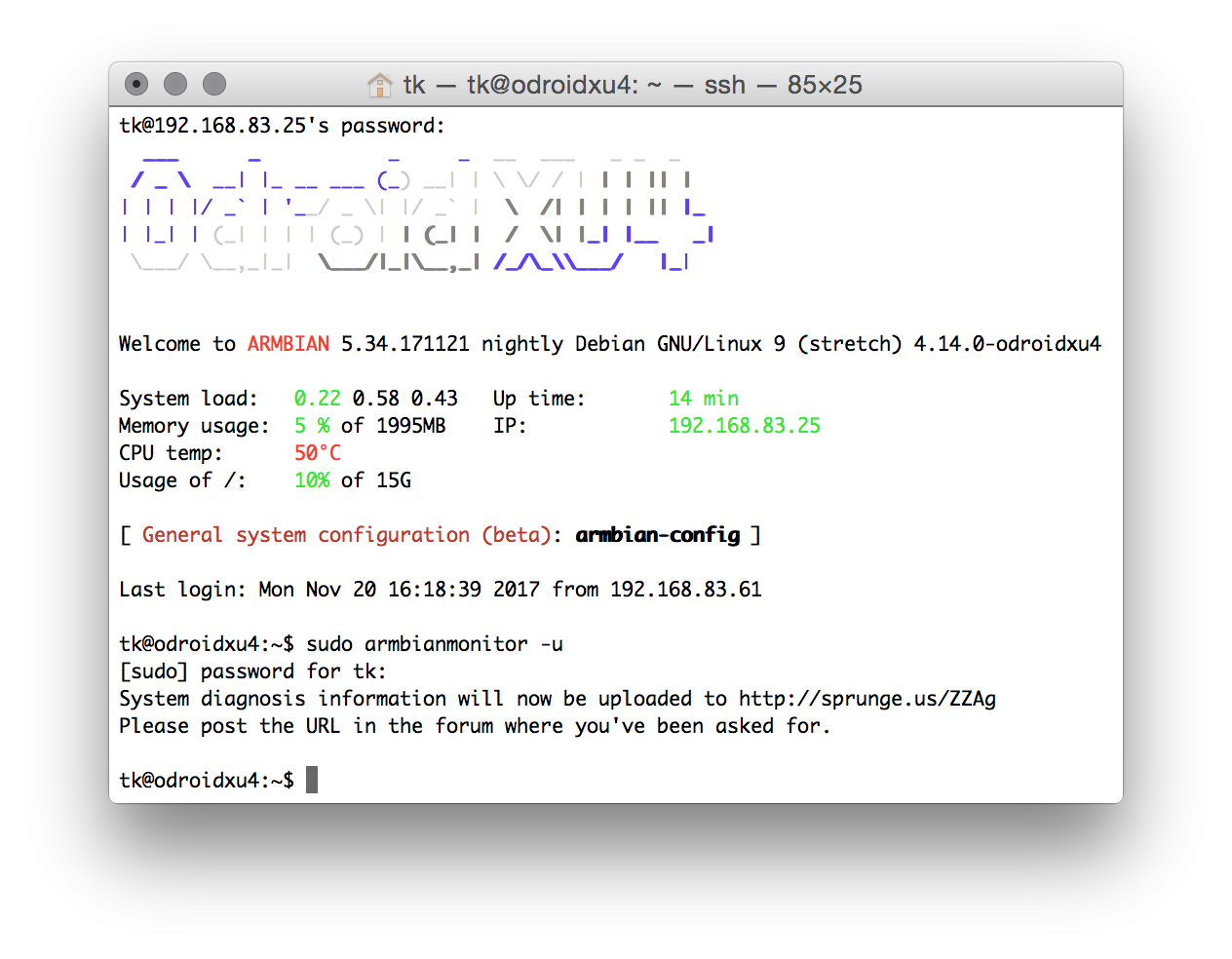
I use the OrangePi Zero. But it is similar to other model. It's very simple: 1) use the mainline 4.11.x kernel 2) enable the uart1 and pps-gpio in /boot/armbianEnv.txt like this : overlays=uart1 pps-gpio param_pps_pin=PA7 3) edit /etc/default/gpsd to use ttyS1 as gps device # Devices gpsd should collect to at boot time. # They need to be read/writeable, either by user gpsd or the group dialout. DEVICES="/dev/ttyS1" # Other options you want to pass to gpsd GPSD_OPTIONS="-G -n " 4) If you use ntpd, edit /etc/ntpd.conf like this: # GPS Serial data reference server 127.127.28.0 minpoll 4 maxpoll 4 prefer fudge 127.127.28.0 time1 0.135 refid GPS server 127.127.22.0 maxpoll 4 # ATOM(PPS) fudge 127.127.22.0 flag3 1 # enable PPS API 5) Or if you prefer crony rather than ntp, install chrony instead of ntp, edit /etc/chrony/chrony.conf , add this to end of it: refclock SHM 0 refid GPS precision 1e-1 offset 0.134 delay 0.2 noselect refclock PPS /dev/pps0 lock GPS 6) connect GPS module to UART1 GPS Zero --------------------- TXD UART1_RX PIN10 RXD UART1_TX PIN8 PPS IO-1 PIN12 7) use ntpq -p or chrony sources. to check it.
-
 Now that there are an increasing number of boards running in 64 bit mode (Aarch64) it might happen that you want/need to run a 32 bit application on a 64 bit OS. I suspect that there is more than one way to do this, but here's what I've been using: dpkg --add-architecture armhf apt-get update apt-get install libc6:armhf libstdc++6:armhf Some applications need the following step to run: cd /lib ln -s arm-linux-gnueabihf/ld-2.23.so ld-linux.so.3 There is a downside to this approach - after adding armhf you have to be careful when installing new packages that you get the right version and don't end up installing 32bit packages that you don't need.
 -
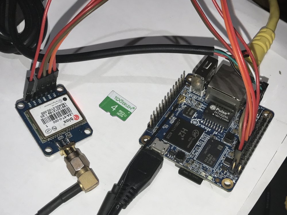
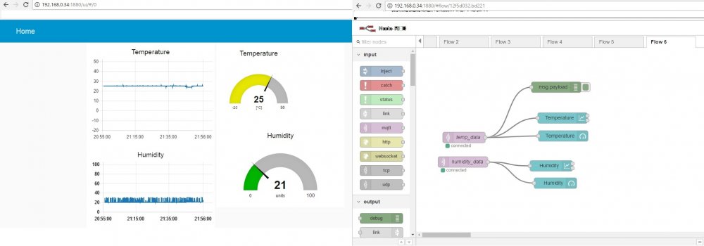
For those of you who are interested in using a OPI zero as a small IoT-Server. I have some hints to get it working. It's more or less a lmgtfy How To plus some arduino code to test if it works. Hardware: OrangePi 0 with Armbian 5.25 connected over lan to my router DHT11 Module on a Wemos D1 mini (a small cheap wlan MCU for ~3$ which can be programmed via the Arduino IDE) Installation: First of all we install node-red on the OPI. Instead of rewrite how to do that again I just give you the link who to do that: Node-Red on armbian Second we install Mosquitto as a mqtt broker. If I have it right in mind I followed this instructable (I'm not shure, it's more than 2 weeks ago and I didn't save the link then): Mosquitto To represent the data of our DHT sensor-node graphically we install the node red dashboard module in: /usr/lib/node_modules/ with npm i node-red-dashboard If everything goes right you should have access to node-red via browser on port 1880: 192.168.1.xx:1880 and to the UI of dashboard: 192.168.1.xx:1880/ui/ Setting up everything: Now we're setting up the Wemos D1 mini. DHT11 wiring (DHT-->Wemos): VCC -->3.3V Signal --> D4 GND -->GND Some of the Wemos pins are capable for 5V (A0 definitly not!) but the DHT readings gets noisier when the device is powered through 5V (don't ask me why, I'm not en electronic engineer...) For the testprogramm we need two libraries which can be installed via the arduino IDE lib manager (+ ESP8266WiFi.h which comes when adding the generic ESP8266 board via Boardmanager): PubSubClient.h (PubSubClient by Nick O'Leary) DHT.h (DHT sensor library by Adafruit) And here comes the simplyfied code publishing to the mqtt broker: The code is more or less a combination of the examples which comes with the PubSubClient & DHT libraries + throw away all the stuff that we don't need (I had also a version of code where the Wemos D1 mini subscribe to the mqtt broker and gets a timestamp injected from node-red which was then added to the published sensor data). Humidity data is stored in the "hum" topic, temperature in "temp". Keep in mind that if you plan use more than one senor-node, you should name the topics properly (see: MQTT topics best practices for more information about proper topic nameing) We can now generate our test-flow on the node-red webpage (See printscreen). Subscribe to the mqtt topics and publish it on the chart and gauge (more information about Dashboard can be found on: Node-Red & Dashboard). Powering the Wemos and deploy the created flow shoud show us the graphs on 192.168.1.xx:1880/ui/ (see picture) To call me an IoT expert is like someone calling tkaiser a fan of micro USB powered SBCs. According to the MIT licence this HowTo is provided "as is", without warranty etc.
-
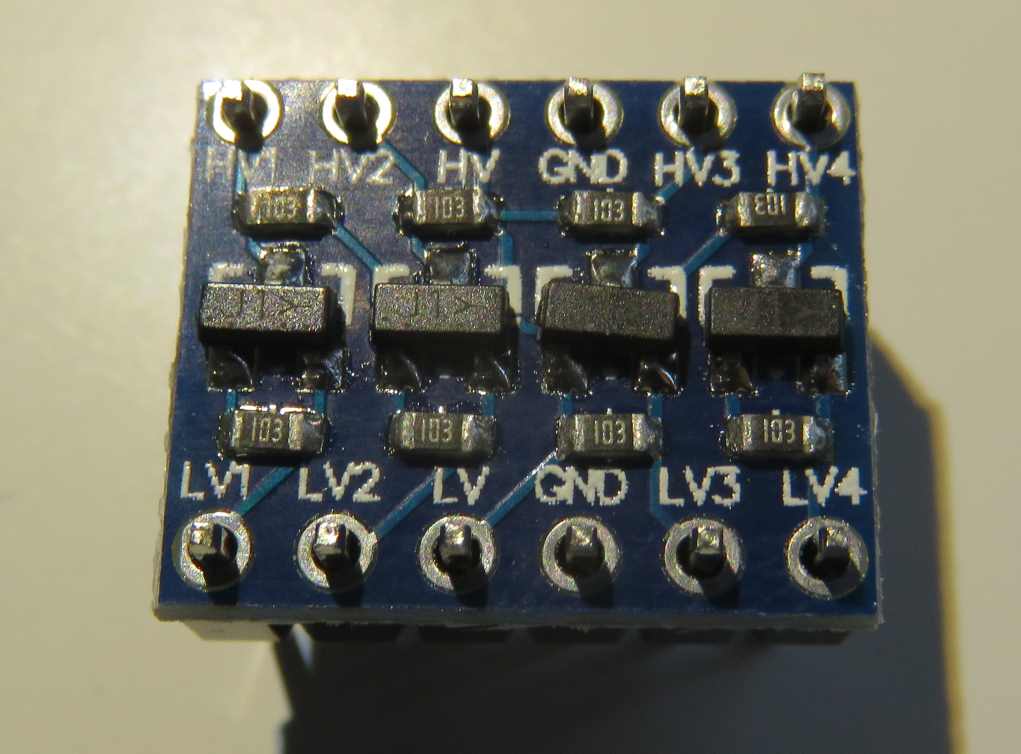
 Hi All, I recently bought a cheap 16 character, 2 row LCD display from aliexpress.com for use with my Orange Pi PC. I got it to work without too much pain, but I thought I would document it here for the benefit of others. Some good instructions are already available on the internet, but there are some tweaks required for the Orange PI. Armbian I believe already has the I2C module compiled into the kernel directly. So no Linux Kernal insmod work required, unlike what many Raspberry PI guides seem to imply. Step 1) Buy the things you will need. 1. You obviously need a 1602 LCD module which also comes with the the I2C converter. You can buy a 1602 LCD and wire it directly to the 16 GPIO pins required if you want, but that isn't the point of this guide. 2. You will need a level shifter. The LCD display works on +5volts. The OrangePI/H3 GPIO pins are 3.3 volts. I have seen guides stating that you don't need a level shifter, but I'm sure you're slowly frying some transistors in your OrangePI over time. 3. You will need a bunch of jumper cables etc. Like these, female to female only required really. Step 2) Wire things up accordingly. Thanks to this fantastic guide, the instructions on wiring the Orange PI to the Level Shifter LV ('low voltage') pins, and then the Level Shifter HV ('high voltage') pins to the 1602 I2C module is pretty clear: http://www.raspberrypi-spy.co.uk/2015/05/using-an-i2c-enabled-lcd-screen-with-the-raspberry-pi/ Level Shifter OrangePI 1602 I2C Backpack LV 3.3V (pin 1) – LV1 SDA (pin 3) – LV2 SCL (pin 5) – GND GND (pin 6) GND HV 5V (pin 2) VCC HV1 SDA HV2 SCL Note, you connect the 1602 I2C module/backpack directly to the 5Volt Pin on the PI (Pin 2 or 4) and Ground (Pin 6) respectively. Note: For some strange reason the level shifter works if you don't connect the ground pins to either side of it (i.e. Use the LV, LV1, LV2, HV, HV1 and HV2 pins only). No idea why - electrical engineering degree required I think. If all works well, you should see the LCD module light-up with the top row being a bunch of white bars (you might need to check the contrast setting of the module as well). White bars = uninitialised LCD screen. Step 3) Install the required packages int Armbian Reference: https://www.abelectronics.co.uk/kb/article/1061/i2c--smbus-and-armbian-linux sudo apt-get install -y python-smbus i2c-tools Step 4) Check to see what the address of the LCD Screen is: Reference: http://www.raspberrypi-spy.co.uk/2014/11/enabling-the-i2c-interface-on-the-raspberry-pi/ user@orangepipc:~/Downloads/i2c$ sudo i2cdetect -y 0 [sudo] password for userpi: 0 1 2 3 4 5 6 7 8 9 a b c d e f 00: -- -- -- -- -- -- -- -- -- -- -- -- -- 10: -- -- -- -- -- -- -- -- -- -- -- -- -- -- -- -- 20: -- -- -- -- -- -- -- -- -- -- -- -- -- -- -- -- 30: -- -- -- -- -- -- -- -- -- -- -- -- -- -- -- 3f 40: -- -- -- -- -- -- -- -- UU -- -- -- -- -- -- -- 50: -- -- -- -- -- -- -- -- -- -- -- -- -- -- -- -- 60: -- -- -- -- -- -- -- -- -- -- -- -- -- -- -- -- 70: -- -- -- -- -- -- -- -- user@orangepipc:~/Downloads/i2c$ sudo i2cdetect -y 1 0 1 2 3 4 5 6 7 8 9 a b c d e f 00: -- -- -- -- -- -- -- -- -- -- -- -- -- 10: -- -- -- -- -- -- -- -- -- -- -- -- -- -- -- -- 20: -- -- -- -- -- -- -- -- -- -- -- -- -- -- -- -- 30: -- -- -- -- -- -- -- -- -- -- -- -- -- -- -- -- 40: -- -- -- -- -- -- -- -- -- -- -- -- -- -- -- -- 50: -- -- -- -- -- -- -- -- -- -- -- -- -- -- -- -- 60: -- -- -- -- -- -- -- -- -- -- -- -- -- -- -- -- 70: -- -- -- -- -- -- -- -- Looks like it's 0x3f as the address on I2C bus 0 (which is apparently right according to the aliexpress buyer feedback comments) Step 5) Download Example Script Reference: http://www.raspberrypi-spy.co.uk/2015/05/using-an-i2c-enabled-lcd-screen-with-the-raspberry-pi/ The example script will allow you to send text to the screen via I2C. It is very similar to my scripts for the normal 16×2 screen. To download the script directly to your Pi you can use : wget https://bitbucket.org/MattHawkinsUK/rpispy-misc/raw/master/python/lcd_i2c.py Step 6) Adjust the Sample Script I need to adjust the script to reference a 1602 LCD device with address 0x3f, on Orange Pi PC I2C Bus, 0. The script as it is references a device of 0x27 on Bus 1 - it won't work. You might have a LCD device of address 0x27 (you'll know from the previous step), but it seems many of the cheap LCD modules from aliexpress are 0x3f for some reason. Adjusted script below: #!/usr/bin/python #-------------------------------------- # ___ ___ _ ____ # / _ \/ _ \(_) __/__ __ __ # / , _/ ___/ /\ \/ _ \/ // / # /_/|_/_/ /_/___/ .__/\_, / # /_/ /___/ # # lcd_i2c.py # LCD test script using I2C backpack. # Supports 16x2 and 20x4 screens. # # Author : Matt Hawkins # Date : 20/09/2015 # # http://www.raspberrypi-spy.co.uk/ # # Copyright 2015 Matt Hawkins # # This program is free software: you can redistribute it and/or modify # it under the terms of the GNU General Public License as published by # the Free Software Foundation, either version 3 of the License, or # (at your option) any later version. # # This program is distributed in the hope that it will be useful, # but WITHOUT ANY WARRANTY; without even the implied warranty of # MERCHANTABILITY or FITNESS FOR A PARTICULAR PURPOSE. See the # GNU General Public License for more details. # # You should have received a copy of the GNU General Public License # along with this program. If not, see <http://www.gnu.org/licenses/>. # #-------------------------------------- import smbus import time # Define some device parameters I2C_ADDR = 0x3f # I2C device address LCD_WIDTH = 16 # Maximum characters per line # Define some device constants LCD_CHR = 1 # Mode - Sending data LCD_CMD = 0 # Mode - Sending command LCD_LINE_1 = 0x80 # LCD RAM address for the 1st line LCD_LINE_2 = 0xC0 # LCD RAM address for the 2nd line LCD_LINE_3 = 0x94 # LCD RAM address for the 3rd line LCD_LINE_4 = 0xD4 # LCD RAM address for the 4th line LCD_BACKLIGHT = 0x08 # On #LCD_BACKLIGHT = 0x00 # Off ENABLE = 0b00000100 # Enable bit # Timing constants E_PULSE = 0.0005 E_DELAY = 0.0005 #Open I2C interface bus = smbus.SMBus(0) # Rev 1 Pi uses 0 (and Orange PI PC, for pins 3 and 5) #bus = smbus.SMBus(1) # Rev 2 Pi uses 1 def lcd_init(): # Initialise display lcd_byte(0x33,LCD_CMD) # 110011 Initialise lcd_byte(0x32,LCD_CMD) # 110010 Initialise lcd_byte(0x06,LCD_CMD) # 000110 Cursor move direction lcd_byte(0x0C,LCD_CMD) # 001100 Display On,Cursor Off, Blink Off lcd_byte(0x28,LCD_CMD) # 101000 Data length, number of lines, font size lcd_byte(0x01,LCD_CMD) # 000001 Clear display time.sleep(E_DELAY) def lcd_byte(bits, mode): # Send byte to data pins # bits = the data # mode = 1 for data # 0 for command bits_high = mode | (bits & 0xF0) | LCD_BACKLIGHT bits_low = mode | ((bits<<4) & 0xF0) | LCD_BACKLIGHT # High bits bus.write_byte(I2C_ADDR, bits_high) lcd_toggle_enable(bits_high) # Low bits bus.write_byte(I2C_ADDR, bits_low) lcd_toggle_enable(bits_low) def lcd_toggle_enable(bits): # Toggle enable time.sleep(E_DELAY) bus.write_byte(I2C_ADDR, (bits | ENABLE)) time.sleep(E_PULSE) bus.write_byte(I2C_ADDR,(bits & ~ENABLE)) time.sleep(E_DELAY) def lcd_string(message,line): # Send string to display message = message.ljust(LCD_WIDTH," ") lcd_byte(line, LCD_CMD) for i in range(LCD_WIDTH): lcd_byte(ord(message[i]),LCD_CHR) def main(): # Main program block # Initialise display lcd_init() while True: # Send some test lcd_string("RPiSpy <",LCD_LINE_1) lcd_string("I2C LCD <",LCD_LINE_2) time.sleep(3) # Send some more text lcd_string("> RPiSpy",LCD_LINE_1) lcd_string("> I2C LCD",LCD_LINE_2) time.sleep(3) if __name__ == '__main__': try: main() except KeyboardInterrupt: pass finally: lcd_byte(0x01, LCD_CMD) Step 7) ADD YOUR USER ACCOUNT TO 'i2c' GROUP This is a really useful thing to do, otherwise you'll need to run the python script as ROOT (via. sudo etc.) every time. No good if you want to write a python script that runs using your normal user account and sends messages over I2C to the LCD. Reference: https://www.abelectronics.co.uk/kb/article/1061/i2c--smbus-and-armbian-linux sudo adduser <YOUR_USER_ID> i2c eg: sudo adduser johnsmith i2c Step 8) Run your script! python lcd_i2c.py Amazing! Please note: You can probably use a more advanced library to output data to the LCD, but for now, it probably isn't required: https://gist.github.com/DenisFromHR (you will need to adjust the code in 'RPi_I2C_driver.py' to refer to port=0, not port=1 to get this to work. Also change the address of the LCD device if required) http://www.circuitbasics.com/raspberry-pi-i2c-lcd-set-up-and-programming/ What a level shifter looks like:
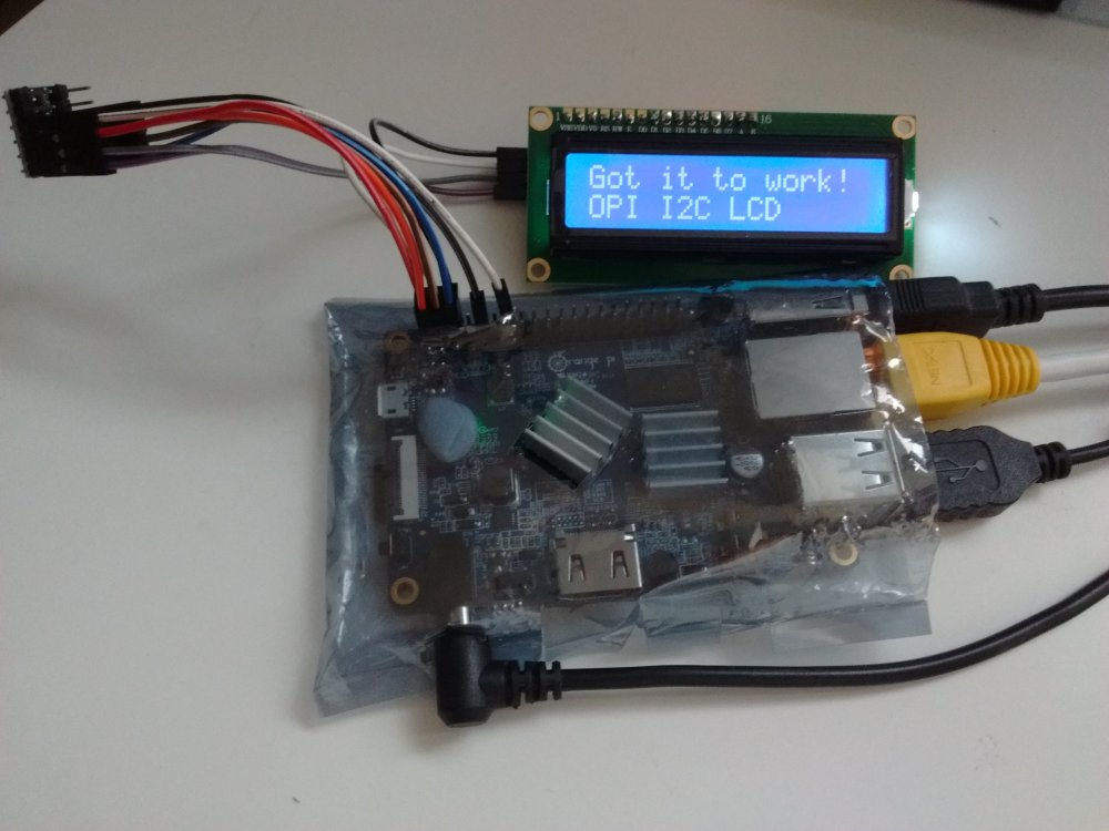
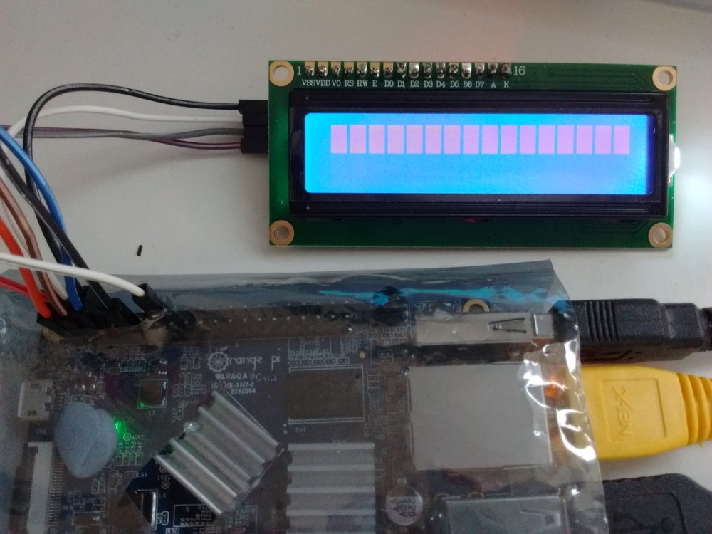

-
 Full root filesystem encryption on an Armbian/Orange Pi PC 2 system MMGen (https://github.com/mmgen) WARNING: This tutorial has been obsoleted by Full root filesystem encryption on an Armbian system. In addition, an automated script is available, which can be downloaded here or by cloning the following repository: git clone https://github.com/mmgen/mmgen-geek-tools This tutorial provides detailed, step-by-step instructions for setting up full root filesystem encryption on an Armbian/Orange Pi PC2 system. With minor changes, it can be adapted to other Armbian-supported boards. The disk is unlocked remotely via ssh, permitting unattended bootup. Requirements: Linux host system One Orange Pi PC 2 Two blank Micro-SD cards (or a working Armbian system for your board + one blank SD card) USB Micro-SD card reader Ability to edit text files and do simple administrative tasks on the Linux command line Part 1 - Get, unpack and copy an Armbian image for your board Create your build directory: $ mkdir armbenc-build && cd armbenc-build Download and unpack an Armbian image for your board and place it in this directory. If you have two blank SD cards, the first will hold an ordinary unencrypted Armbian system used for the setup process, while the second will hold the target encrypted system. Alternatively, if you already have a working Armbian system for your board, you can use it for the setup process. In that case, your one blank SD card will be considered the “second” card, and you can ignore all instructions hereafter pertaining to the first card. Note that for the remainder of this section, the first SD card will be referred to as '/dev/sdX' and the second as '/dev/sdY'. You'll replace these with the SD cards' true device filenames. The device names can be discovered using the command 'dmesg' or 'lsblk'. If you remove the first card before inserting the second, it's possible (but not guaranteed) that the cards will have the same device name. Insert the first blank SD card and copy the image to it: $ sudo dd if=$(echo *.img) of=/dev/sdX bs=4M After the command exits, you may remove the first card. Now insert the second SD card, which will hold a small unencrypted boot partition plus your encrypted Armbian system. Copy the image's boot loader to it: $ sudo dd if=$(echo *.img) of=/dev/sdY bs=512 count=32768 Now partition the card: $ sudo fdisk /dev/sdY Within fdisk, create a new DOS disklabel with the 'o' command. Use the 'n' command to create a primary partition of size +200M beginning at sector 32768. Type 'p' to view the partition table. Note the end sector. Now create a second primary partition beginning one sector after the first partition's end sector and filling the remainder of the card. When you're finished, your partition table will look something like this: Device Boot Start End Sectors Size Id Type /dev/sdY1 32768 442367 409600 200M 83 Linux /dev/sdY2 442368 123596799 123154432 58.7G 83 Linux Double-check that the second partition begins one sector after the end of the first one. If you mess something up, use 'd' to delete partitions or 'q' to exit fdisk and try again. Once everything looks correct, type 'w' to write the partition table. Now you'll begin the process of copying the system to the second card. First you'll associate the image file with a loop device and mount the device: $ losetup -f # displays the name of the loop device; remember this $ sudo losetup -Pf *.img # associate image file with the above loop device $ mkdir mnt boot root $ sudo mount /dev/loopXp1 mnt # replace '/dev/loopX' with the above loop device Create a filesystem on the SD card's boot partition and copy the boot partition data from the image file to it: $ sudo mkfs.ext4 /dev/sdY1 $ sudo e2label /dev/sdY1 OPI_PC2_BOOT # don't omit this step! $ sudo mount /dev/sdY1 boot $ sudo cp -av mnt/boot/* boot $ (cd boot; sudo ln -s . boot) Create the encrypted root partition (for this the 'cryptsetup-bin' package must be installed on the host). You'll be prompted for a passphrase. It's recommended to choose an easy one like 'abc' for now. The passphrase can easily be changed later (consult the 'cryptsetup' man page for details): $ sudo cryptsetup --pbkdf argon2i --pbkdf-memory 600000 luksFormat /dev/sdY2 Note that the --pbkdf-memory argument must be less than the available free memory in kilobytes at bootup time. Otherwise you’ll get an out-of-memory error and your disk will fail to unlock. 600000 is a safe value for the Orange Pi PC2 with its 1GB of RAM. Activate the encrypted root partition, create a filesystem on it and mount it: $ sudo cryptsetup luksOpen /dev/sdY2 foo # enter your passphrase from above $ sudo mkfs.ext4 /dev/mapper/foo $ sudo mount /dev/mapper/foo root Copy the system to the encrypted root partition: $ (cd mnt && sudo rsync -av --exclude=boot * ../root) $ sync # be patient, this could take a while $ sudo mkdir root/boot $ sudo touch root/root/.no_rootfs_resize Unmount the mounted image and second SD card, and free the loop device and encrypted mapping: $ sudo umount mnt boot root $ sudo losetup -d /dev/loopX $ sudo cryptsetup luksClose foo From here on, all your work will be done on the Orange Pi. Part 2 - boot into the unencrypted Armbian system If applicable, insert the first (unencrypted) SD card into the Pi's Micro-SD card slot. Insert a USB card reader holding the second SD card into a USB port on the Pi. Boot the Pi. If applicable, log in as root with password '1234', follow the password update instructions, and stay logged in as root. The following steps will be performed from a root shell. Part 3 - set up the unencrypted Armbian system Update the APT package index and install cryptsetup: # apt-get update # apt-get install cryptsetup Part 4 - set up the encrypted Armbian system Prepare the encrypted system chroot: # BOOT_PART=($(lsblk -l -o NAME,LABEL | grep OPI_PC2_BOOT)) # ROOT_PART=${BOOT_PART%1}2 # cryptsetup luksOpen /dev/$ROOT_PART foo # mkdir /mnt/enc_root # mount /dev/mapper/foo /mnt/enc_root # mount /dev/$BOOT_PART /mnt/enc_root/boot # cd /mnt/enc_root # mount -o rbind /dev dev # mount -t proc proc proc # mount -t sysfs sys sys Copy some key files so you'll have a working Internet connection within the chroot: # cat /etc/resolv.conf > etc/resolv.conf # cat /etc/hosts > etc/hosts Now chroot into the encrypted system. From this point on, all work will be done inside the chroot: # chroot . # apt-get update # echo 'export CRYPTSETUP=y' > /etc/initramfs-tools/conf.d/cryptsetup # apt-get install cryptsetup-initramfs dropbear-initramfs # for focal and buster # apt-get install cryptsetup dropbear-initramfs # for bionic Check to see that the cryptsetup scripts are present in the initramfs (command should produce output): # gunzip -c /boot/initrd.img* | cpio --quiet -t | grep cryptsetup Edit '/etc/fstab' to look exactly like this: /dev/mapper/rootfs / ext4 defaults,noatime,nodiratime,commit=600,errors=remount-ro 0 1 /dev/mmcblk0p1 /boot ext4 defaults,noatime,nodiratime,commit=600,errors=remount-ro 0 2 tmpfs /tmp tmpfs defaults,nosuid 0 0 Add the following lines to '/etc/initramfs-tools/initramfs.conf'. If the Orange Pi's IP address will be statically configured, substitute the correct static IP address after 'IP='. If it will be configured via DHCP, omit the IP line entirely: DEVICE=eth0 IP=192.168.0.88:::255.255.255.0::eth0:off Add the following parameters to the quoted bootargs line in '/boot/boot.cmd'. Note that the 'root' parameter replaces the existing one: root=/dev/mapper/rootfs cryptopts=source=/dev/mmcblk0p2,target=rootfs If you want to be able to unlock the disk from the virtual console (which you probably do) as well as via ssh, then comment out the following line: # if test "${console}" = "serial" || test "${console}" = "both"; then setenv consoleargs "${consoleargs} console=ttyS0,115200"; fi In case you're wondering, 'setenv console "display"' doesn't work. Don't ask me why. Compile the boot menu: # mkimage -C none -A arm -T script -d /boot/boot.cmd /boot/boot.scr Copy the SSH public key from the machine you'll be unlocking the disk from to the Armbian machine: # rsync yourusername@remote_machine:.ssh/id_*.pub /etc/dropbear-initramfs/authorized_keys If you'll be unlocking the disk from more than one host, then edit the authorized_keys file by hand and add the additional SSH public keys. Edit '/etc/dropbear-initramfs/config', adding the following lines: DROPBEAR_OPTIONS="-p 2222" DROPBEAR=y Reconfigure dropbear: # dpkg-reconfigure dropbear-initramfs Make sure everything was included in the initramfs (both commands should produce output): # gunzip -c /boot/initrd.img* | cpio --quiet -t | grep dropbear # gunzip -c /boot/initrd.img* | cpio --quiet -t | grep authorized_keys Your work is finished! Exit the chroot and shut down the Orange Pi: # exit # halt -p Swap the SD cards and restart the Pi. Unlock the disk by executing the following command on your remote machine. Substitute the Pi's correct static or DHCP-configured IP address for the one below. If necessary, also substitute the correct disk password in place of 'abc': $ ssh -p 2222 -x root@192.168.0.88 'echo -n abc > /lib/cryptsetup/passfifo' If you choose to unlock the disk from the tty, just enter your disk password and hit ENTER. If all went well, your root-filesystem encrypted Armbian system is now up and running!
 -
 Requirements Fresh enough nighly or manually built image Latest kernel and dtb packages (26.03.2017 or newer) Limitations As stated in other PWM related threads, hardware PWM output is supported only on pin PA5 which is also UART0 ("debug" serial console) RX pin, so enabling PWM will disable this console. Activation Add "pwm" to "overlays" line in /boot/armbianEnv.txt Example: overlays=pwm Reboot is required to apply the changes Armbian overlays documentation: https://docs.armbian.com/User-Guide_Allwinner_overlays/ PWM sysfs interface Official documentation: https://git.kernel.org/pub/scm/linux/kernel/git/stable/linux-stable.git/tree/Documentation/ABI/testing/sysfs-class-pwm?h=v4.10 Please note that this ABI is considered "testing" so it may change in the future. Sysfs interface example # activate the PWM. On H3 only 1 PWM is supported, so exporting PWM 0 echo 0 > /sys/class/pwm/pwmchip0/export # set period to 10ms echo 10000000 > /sys/class/pwm/pwmchip0/pwm0/period # set normal polarity. needs to be reset explicitly. Bug? echo "inversed" > /sys/class/pwm/pwmchip0/pwm0/polarity echo "normal" > /sys/class/pwm/pwmchip0/pwm0/polarity # enable the PWM echo 1 > /sys/class/pwm/pwmchip0/pwm0/enable # set duty cycle to 1ms echo 1000000 > /sys/class/pwm/pwmchip0/pwm0/duty_cycle Result: # set duty cycle to 2ms echo 2000000 > /sys/class/pwm/pwmchip0/pwm0/duty_cycle Result: # set duty cycle to 1us, period to 2us echo 1000 > /sys/class/pwm/pwmchip0/pwm0/duty_cycle echo 2000 > /sys/class/pwm/pwmchip0/pwm0/period Result: Please note that some settings needs to be changed in a correct sequence, i.e. you can't set duty cycle higher than period root@orangepiplus2e:~# echo 1000 > /sys/class/pwm/pwmchip0/pwm0/duty_cycle root@orangepiplus2e:~# echo 500 > /sys/class/pwm/pwmchip0/pwm0/period -bash: echo: write error: Invalid argument root@orangepiplus2e:~#
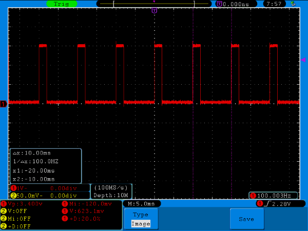
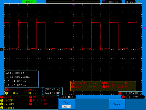
-
 UPDATE 11-FEB-2017: Version 2.2.0 is released: now including video recording in stead of only images and also a privacy option to black out areas that may not be filmed. UPDATE 09-FEB-2017: Version 2.2.1 is released: memory leak(s) fixed and in some cases video stopped recording. This should be fixed now. Download via this page. Kerberos.io (link) is a relative new video surveillance program focusing mainly on the Raspberry Pi. In collaboration with the owner of the github project I managed to get it working on my Orange Pi Plus and PCDuino3 nano using Armbian (Debian Jessie) and a Logitech UVC compatible USB webcam. It consists of 2 modules: the Machinery module and Web module. The machinery module was very Raspberry Pi specific, but is now updated and can also run with very little extra effort on Armbian. The Web module runs without any modification. Follow the instructions below and you should be able to install or compile it. Kerberos.io is very fast and has a modern interface. Furthermore it is (IMHO) a very nice alternative for zoneminder and motion.It also provides a videostream on a webpage. Follow the instructions below and share your comments, ideas etc. Method 1 (easy) - Install on Armbian Debian Jessie. Follow the instructions on the dedicated Armbian page (link). Here you will find an Armbian precompiled .deb armhf package. Further installation / configuration options can be found on the Kerberios.io webpages. Method 2 (advanced) - Compiling the machinery and web module on Armbian Debian Jessie. Install the following packages: sudo apt-get install pkg-config libavcodec-dev libavformat-dev libswscale-dev Follow the instructions on this page (link). Further installation / configuration options can be found on the Kerberios.io webpages. In all cases: please note that you must alter the camera configuration: default it comes with the Raspberry Pi camera that you probably won't have!
 -
 If you follow https://github.com/ejurgensen/forked-daapd you will get a lot of error-messages. Here is guide to install it on your Orange Pi Pc (Debian Jessie), sudo apt-get install build-essential git autotools-dev autoconf libtool gettext gawk gperf \ antlr3 libantlr3c-dev libconfuse-dev libunistring-dev libsqlite3-dev \ libavcodec-dev libavformat-dev libavfilter-dev libswscale-dev libavutil-dev \ libasound2-dev libmxml-dev libgcrypt11-dev libavahi-client-dev zlib1g-dev \ libevent-dev for Armbian you need some little extras installed sudo apt-get install libcurl4-gnutls-dev sudo apt-get install libjson0 libjson0-dev sudo apt-get install avahi-daemon avahi-discover libnss-mdns then you run git clone https://github.com/ejurgensen/forked-daapd.git cd forked-daapd autoreconf -i ./configure --prefix=/usr --sysconfdir=/etc --localstatedir=/var make sudo make install create the new user sudo adduser daapd adjust the settings for your music-path in /etc/forked-daapd.conf on my Orange Pi, the file /etc/init.d/forked-daapd was missing. If yours is missing, too, just add it: sudo nano /etc/init.d/forked-daapd and copy this text inside: #! /bin/sh ### BEGIN INIT INFO # Provides: forked-daapd # Required-Start: $local_fs $remote_fs $network $time avahi # Required-Stop: $local_fs $remote_fs $network $time # Default-Start: 2 3 4 5 # Default-Stop: 0 1 6 # Short-Description: media server with support for RSP, DAAP, DACP and AirTunes # Description: forked-daapd is an iTunes-compatible media server for # sharing your music library over the local network with RSP # clients like the SoundBridge from Roku and DAAP clients like # iTunes. It can also stream music to AirTunes devices. ### END INIT INFO PATH=/usr/local/sbin:/usr/local/bin:/sbin:/bin:/usr/sbin:/usr/bin DAEMON=/usr/sbin/forked-daapd NAME=forked-daapd DESC="RSP and DAAP media server" test -x $DAEMON || exit 0 PIDFILE=/var/run/$NAME.pid set -e running_pid() { # Check if a given process pid's cmdline matches a given name pid=$1 name=$2 [ -z "$pid" ] && return 1 [ ! -d /proc/$pid ] && return 1 cmd=`cat /proc/$pid/cmdline | tr "\000" "\n"|head -n 1 |cut -d : -f 1` # Is this the expected child? [ "$cmd" != "$name" ] && return 1 return 0 } running() { # Check if the process is running looking at /proc # (works for all users) # No pidfile, probably no daemon present [ ! -f "$PIDFILE" ] && return 1 # Obtain the pid and check it against the binary name pid=`cat $PIDFILE` running_pid $pid $DAEMON || return 1 return 0 } force_stop() { # Forcefully kill the process [ ! -f "$PIDFILE" ] && return if running ; then kill -15 $pid # Is it really dead? if running ; then kill -9 $pid if running ; then echo "Cannot kill $NAME (pid=$pid)!" exit 1 fi fi fi rm -f $PIDFILE return 0 } case "$1" in start) echo -n "Starting $DESC: " start-stop-daemon --start --quiet --pidfile $PIDFILE \ --exec $DAEMON -- $DAEMON_OPTS if running ; then echo "$NAME." else echo " ERROR." fi ;; stop) echo -n "Stopping $DESC: " start-stop-daemon --oknodo --stop --quiet --pidfile $PIDFILE \ --exec $DAEMON echo "$NAME." ;; force-reload) start-stop-daemon --stop --test --quiet --pidfile \ /var/run/$NAME.pid --exec $DAEMON \ && $0 restart \ || exit 0 ;; restart) PID=$(cat $PIDFILE 2> /dev/null || true) echo -n "Restarting $DESC: " start-stop-daemon --stop --quiet --oknodo --pidfile \ /var/run/$NAME.pid --exec $DAEMON if [ -n "$PID" ]; then while running_pid $PID $DAEMON; do echo -n "."; sleep 1; done fi start-stop-daemon --start --quiet --pidfile \ /var/run/$NAME.pid --exec $DAEMON -- $DAEMON_OPTS echo "$NAME." ;; status) echo -n "$NAME is " if running ; then echo "running" else echo " not running." exit 1 fi ;; *) N=/etc/init.d/$NAME echo "Usage: $N {start|stop|restart|force-reload|status}" >&2 exit 1 ;; esac exit 0 Save it. Now we need to allow the service access to it´s own database: sudo chown -R daapd /var/cache/forked-daapd Start the service: sudo /etc/init.d/forked-daapd restart tail -f /var/log/forked-daapd.log you should see some activity on the log-file. After the scanning is complete, you can see your Orange Pi music-server in iTunes. Automatic updates for the music-server (e.g. at 4am in the morning, necessary if you use a network-share for the data): sudo crontab -e and add the line 0 4 * * * touch /{path to your music}/trigger.init-rescan
 -
Questions and answers about powering the Orange Pi Zero using the "Power over Ethernet" option. The aim is to answer community questions about Power Over Ethernet options (both official 802.3af/at and unofficial "PoE" solutions) and to improve the wiki page with these answers: http://linux-sunxi.org/Xunlong_Orange_Pi_Zero Helpful links: http://linux-sunxi.org/Xunlong_Orange_Pi_Zero#Powering_the_board https://en.wikipedia.org/wiki/Power_over_Ethernet https://forum.armbian.com/index.php/topic/1762-new-oranges-with-h5-and-h2/page-2#entry19054 Examples of standards-compliant PoE hardware: 802.3af switch: https://www.amazon.com/TP-Link-8-Port-Ethernet-Desktop-TL-SF1008P/dp/B003CFATT2/ 100MBit 802.3af to 5V power supply (10W max): https://www.aliexpress.com/item/1PCS-Micro-USB-Active-POE-Splitter-Power-48V-to-5V-2-4A-for-Raspberry-pi-3/32741378583.html Gigabit 802.3af to 12/9/5V power supply (12W max): http://www.tp-link.com/en/products/details/cat-4794_TL-POE10R.html Examples of non-standards-compliant PoE hardware: 8 port "PoE" injector (you pick the input voltage): https://www.aliexpress.com/item/Cameye-8-Channel-CCTV-POE-Injector-for-Surveillance-IP-Cameras-Power-over-Ethernet-Adapter-with-Shell/32745669802.html "PoE" splitter: https://www.aliexpress.com/item/POE-Adapter-cable-Tape-Screened-Passive-Power-Over-Ethernet-RJ45-Injector-Splitter-Kit-12-48v-Synthesizer/32516398486.html https://www.aliexpress.com/item/10cm-3-9-5-5mm-x-2-1mm-DC-Female-to-Micro-USB-Male-Charging-Cable/32319957922.html (Zero soldering option!) Solder to pads on Orange Pi Zero and use a DC-DC step down converter to get 5V: https://www.aliexpress.com/item/5-pcs-Ultra-Small-Size-DC-DC-Step-Down-Power-Supply-Module-3A-Adjustable-Step-Down/32261885063.html https://www.aliexpress.com/item/15924-Free-shipping-DC-DC-Step-Down-Converter-Module-LM2596-DC-4-0-40-to-1/32354635261.html https://www.aliexpress.com/item/24V-12V-To-5V-5A-DC-DC-Buck-Step-Down-Power-Supply-Module-Synchronous-Rectification-Power/32689938167.html Q&A: 1. The Orange Pi Zero says it supports "PoE" how is this implemented? The Ethernet port on the Orange Pi Zero exposes pins 4/5 and 7/8 via pads on the bottom of the board. Photo here. Note that this is 802.3af mode B, which is not fully standards compliant (802.3af/at specifies mode A and mode B, it is not allowed to have a device which only accepts one mode). Out of the box, there is NO way to power the board from Ethernet, either with an 802.3af/at switch or with passive "PoE" injectors. More effort is needed. 2. What are the options to power the Orange Pi with "PoE" ? Option 1: Solder 0 Ohm resistors across the pads and use a PoE injector with 5V. Pro: + No additional power supply needed Con: - 5V cannot travel long distances without voltage sag. You can put in a higher voltage (e.g. 7V DC) but then all the cables would need to be the same length and you risk destroying the Orange Pi if the voltage spikes. Option 2: Solder a step-down converter and use a PoE injector with a higher voltage (e.g. 24V). Pro: + 24V will travel much farther than 5V in a CAT5/6 cable. Cons: - You will need to purchase and solder an additional voltage regulator to take the input voltage and drop it down to 5V. Option 3: Buy/use a PoE switch implementing 802.3af/at. Pro: + Standards compliant + 802.3af/at operate at ~48V, which can power devices up to 100m away from the switch + Plugging in a non-PoE device will not result in fireworks + Cable faults will not result in short circuits because the switch will shut down the port Con: - Power electronics to turn 48V into 5V may consume more power than the Orange Pi itself - More expensive
-
There have been several disjointed tutorials on making a raspberrypi or orangepi into a surveillance camera. So I threw this together to maybe help someone out there with any issues. I used the orangepipc+ but any orangepi board should work as long as it has the basics, internet connectivity, storage, and a camera. (I highly suggest heatsinks as well) any feedback or enhancements to this tutorial are greatly appreciated. ------------------------------------------------------------------ ORANGEPI IPCAMERA ------------------------------------------------------------------ su root apt-get update apt-get upgrade apt-get install wget https://github.com/ccrisan/motioneye/wiki/precompiled/ffmpeg_3.1.1-1_armhf.deb dpkg -i ffmpeg_3.1.1-1_armhf.deb apt-get remove libavcodec-extra-56 libavformat56 libavresample2 libavutil54 apt-get install python-pip python-dev curl libssl-dev libcurl4-openssl-dev libjpeg-dev libx264-142 libavcodec56 libavformat56 libmysqlclient18 libswscale3 libpq5 wget https://github.com/Motion-Project/motion/releases/download/release-4.0.1/pi_jessie_motion_4.0.1-1_armhf.deb dpkg -i pi_jessie_motion_4.0.1-1_armhf.deb pip install motioneye mkdir -p /etc/motioneye cp /usr/local/share/motioneye/extra/motioneye.conf.sample /etc/motioneye/motioneye.conf mkdir -p /var/lib/motioneye cp /usr/local/share/motioneye/extra/motioneye.systemd-unit-local /etc/systemd/system/motioneye.service systemctl daemon-reload systemctl enable motioneye systemctl start motioneye sudo modprobe gc2035 sudo modprobe vfe_v4l2 systemctl restart motioneye Accessing The Frontend After having successfully followed the installation instructions, the motionEye server should be running on your system and listening on port 8765. Fire up your favorite web browser and visit the following URL (replacing [your_ip] with... well, your system's IP address): http://[your_ip]:8765/ Use admin with empty password when prompted for credentials. For further details on how to configure motionEye, see Configuration. ------------------------------------------------------------------ FOR UPDATES; ------------------------------------------------------------------ pip install motioneye --upgrade systemctl restart motioneye sudo nano /etc/motioneye/motioneye.conf ctrl+x then y (nano) Modifiy the motion.config file to turnoff localhost; stream_localhost off change the port to 80 from 8765 if desired by; systemctl enable motion systemctl start motion Tutorial sources; https://github.com/ccrisan/motioneye/wiki/Install-On-Raspbian http://www.orangepi.org/orangepibbsen/forum.php?mod=viewthread&tid=941 http://www.orangepi.org/orangepibbsen/forum.php?mod=viewthread&tid=1988 (some resources for motion) http://www.cnx-software.com/2015/09/26/how-to-use-orange-pi-camera-in-linux-with-motion/(VERY OLD) WIP tutorial, I want to add a version with facial recognition using openface and a version using ALPR (automatic license plate recognition, as the orangepi systems can have 2GB of ram) Update 1 09/30/16; seems there is a issue with motioneye and being unable to find the csi camera. I'm trying to find a work around, any help is appreciated. Update 2 11/05/2016 Updated motioneye installation added information on motion and basic setup (incomplete) the editor seems to be breaking my wget addresses I forgot to add the login information and frontend... *DOH*
-
Hi All, After I accomplished my IR Red Key Rick Rolling experiment the other day with much success, and from general end-luser use with Armbian, there were two things which irritated me, which are namely due to the default ALSA configuration that comes with stock Debian and that Armbian inherits. These were: Update: 11 September 2017. This guide will not work for newer Armbiam (Debian) installations which comes with Pulseaudio by default. If you really want what this tutorial provides, you will need to uninstall pulseaudio first: sudo apt-get remove pulseaudio 1) You can't have simultaneous applications using an Audio device. So, how about if I want to stream Internet Radio with 'Radio Tray' but also get system alert sounds, or anything else? Out of luck, you'll get (for example): [ao/alsa] Playback open error: Device or resource busy 2) I want to actually have audio going out of the 3.5mm jack (don't really care about video out), better still if it's the same/simultaneous to what is going out via. HDMI. That means if I have a HDMI TV connected then I can get the sound from the TV, if I don't, then I can just use the 3.5mm jack (i.e. If I'm using my Pi to play Rick Astley headless/without a TV). No need to keep editing /etc/asound.conf every time. Solution? Step 1) Fix the mute on the analog Line-Out in alsamixer (for a start) There's a lot of noise out there about people not being able to get any sound our of the analog Line-Out jack even when having changed /etc/asound.conf. The reason for this is likely due to a mute by default on the analog audio line-out (i.e. the 3.5mm headphone jack) in alsa that you would unlikely to be aware of. I only found this out thanks to a comment here, otherwise I would have thrown by Pi PC out the window today. So to fix, you need to type in the console: sudo alsamixer Then F6 select the 'audiocodec', then tap the right arrow key to select the 'Audio lineout [Off]' item. Press 'm' and you'll get the green 'OO', which means it's now active. Exit alsamixer, and when you're back at the console type: sudo alsactl store 0 ... to store you mixer settings. For your information, the mixer settings are stored to the file: /var/lib/alsa/asound.state ... and if you do a diff of this file after having made the changes in alsamixer, this is what is changed in the alsa asound.state file: control.9 { control.9 { iface MIXER iface MIXER name 'Audio lineout' name 'Audio lineout' value false | value true comment { comment { access 'read write' access 'read write' type BOOLEAN type BOOLEAN count 1 count 1 } } } } Step 2) Change the /etc/asound.conf file As you might or might not be aware, the default /etc/asound.conf file looks something like this: pcm.!default { type hw card 1 } ctl.!default { type hw card 1 } All it is configured to do is give applications direct access to the hardware audio device, and pump the sound either out to the analogue line-out ('card 0') or via HDMI ('card 1'). Pretty basic, but does the job. However, what I wanted was two things: Software mixing before the resulting PCM/Sound is sent to the hardware audio device - This enables me to listen to Internet Radio and Youtube at the same time... Simultaneous Output to both HDMI and analog line-out. If you want only (1) above, and only via HDMI, then the /etc/asound.conf file is this: pcm.!default { type plug slave.pcm "dmixer" } pcm.dmixer { type dmix ipc_key 1024 slave { pcm "hw:1,0" # "hw:1,0" means HDMI change to "hw:0,0" for analog lineout jack output period_time 0 period_size 1024 buffer_size 4096 rate 44100 } bindings { 0 0 1 1 } } ctl.dmixer { type hw card 0 } ctl.!default { type hw card 0 } If you want (1) and (2) (which of course you do), then the /etc/asound.conf file is this: # Thanks to: http://alsa.opensrc.org/Asoundrc#Dupe_output_to_multiple_cards # https://sourceforge.net/p/alsa/mailman/message/33476395/ # Check that a MUTE doesn't exist on the Audio Line Out for Orange PI PC # or you'll get no sound other than via HDMI pcm.!default { type plug slave.pcm "duplicate" } ctl.!default { type hw card 0 } # Create the Software Mixer for HDMI and then link to hardware pcm.hdmi-dmixer { type dmix ipc_key 1024 slave { #pcm "hw:0,0" # pcm "duplicate" pcm "hdmi-hw" # pcm "analog-hw" period_time 0 period_size 1024 buffer_size 4096 rate 44100 } bindings { 0 0 1 1 } } ctl.hdmi-dmixer { type hw card 0 } # Create the Software Mixer for Analogue Out and then link to hardware pcm.analog-dmixer { type dmix ipc_key 2048 slave { #pcm "hw:0,0" # pcm "duplicate" # pcm "hdmi-hw" pcm "analog-hw" period_time 0 period_size 1024 buffer_size 4096 rate 44100 } bindings { 0 0 1 1 } } ctl.analog-dmixer { type hw card 0 } # Route the audio requests to both hardware devices via the mixer. # For some reason we can't have one mixer and then route to two hardware # devices (would be more efficient). pcm.duplicate { type route slave.pcm { type multi slaves { a { pcm "analog-dmixer" channels 2 } h { pcm "hdmi-dmixer" channels 2 } } bindings [ { slave a channel 0 } { slave a channel 1 } { slave h channel 0 } { slave h channel 1 } ] } ttable [ [ 1 0 1 0 ] [ 0 1 0 1 ] ] } ctl.duplicate { type hw; card 0; } # Physical Output Device Mappings - Analogue and HDMI for Orange PI PC pcm.analog-hw { type hw card 0 } pcm.hdmi-hw { type hw card 1 } There you have it. The only downside is that CPU usage for playing music will increase a bit as ALSA will essentially route inputs from applications to two Software Mixers, which are connected to the HDMI and Analog Line-Out hardware devices separately. For some reason you can't have a single Software Mixer route to two hardware devices (or I couldn't get it to work), but whatever. We're talking 20% CPU usage vs. 10% on one core, to play music.
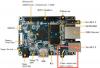
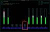

-
Note: Guide Updated May 2017, as I realise that /dev/input/event3 may not always be the IR receiver device on your armbian installation. Hi All, I recently bought an Orange PI PC and the best thing I ever did was install Armbian straight away (and donate). Now that I have a bit of spare time, I wanted to configure my Orange PI PC to do something ridiculous like play Rick Ashley 'Never going to give you up' upon pressing the 'red button' on some generic Chinese IR remote for an LED light strip I have in my living room. Thanks to Armbian, most of the pieces are in place (such as the SunXI IR package) with the distribution, you just need to glue it all together. However there are few configuration issues with the default Armbian install on the Orange PI PC that need to be adjusted, otherwise you'll encounter infuriating issues such as: No IR device existing or being detected (root cause: sunxi-cir module not loaded) No LIRC 'irw' output even after successfully using irrecord (root cause: DRIVER=devinput doesn't work, though it could be my remote), like this poor sod was experiencing. I should also note that this guide on the terrible Orange PI forums, helped me with my issues. Step 1) Adjust /etc/lirc/hardware.conf Updated: This guide was originally written for Armbian based on Debian 'Jessie'. The latest Armbian (as at September 2017) is now based on Ubuntu Xenial. This introduces a new lirc package which yet again comes with a broken hardware.conf For Ubuntu Xenial (September 2017): The default hardware.conf that comes with Armbian is broken. It's assigning the 'remote' and 'transmitter' to the same device, this breaks everything. Ensure the TRANSMITTER_MODULES="" and TRANSMITTER_DEVICE = "" # /etc/lirc/hardware.conf # #Chosen Remote Control REMOTE="None" REMOTE_MODULES="sunxi_cir" REMOTE_DRIVER="default" REMOTE_DEVICE="/dev/lirc0" REMOTE_SOCKET="" # FYI - /run/lirc/lircd will probably be the socket that the system uses REMOTE_LIRCD_CONF="" REMOTE_LIRCD_ARGS="" #Chosen IR Transmitter TRANSMITTER="None" TRANSMITTER_MODULES="" TRANSMITTER_DRIVER="" TRANSMITTER_DEVICE="/dev/null" TRANSMITTER_SOCKET="" TRANSMITTER_LIRCD_CONF="" TRANSMITTER_LIRCD_ARGS="" #Disable kernel support. #Typically, lirc will disable in-kernel support for ir devices in order to #handle them internally. Set to false to prevent lirc from disabling this #in-kernel support. #DISABLE_KERNEL_SUPPORT="true" #Enable lircd START_LIRCD="true" #Don't start lircmd even if there seems to be a good config file #START_LIRCMD="false" #Try to load appropriate kernel modules LOAD_MODULES="true" # Default configuration files for your hardware if any LIRCMD_CONF="" #Forcing noninteractive reconfiguration #If lirc is to be reconfigured by an external application #that doesn't have a debconf frontend available, the noninteractive #frontend can be invoked and set to parse REMOTE and TRANSMITTER #It will then populate all other variables without any user input #If you would like to configure lirc via standard methods, be sure #to leave this set to "false" FORCE_NONINTERACTIVE_RECONFIGURATION="false" START_LIRCMD="" For Debian Jessie (~year 2016): By default Armbian doesn't have the suxi-cir module enabled at boot-up, but it is available, so you will need to edit hardware.conf to enable this, as well as correct the DRIVER= line and the DEVICE= line, as the defaults in there are WRONG. Also I suggest commenting out Igor's code in the top five lines. A hardware.conf that works: # Cubietruck automatic lirc device detection by Igor Pecovnik #str=$(cat /proc/bus/input/devices | grep "H: Handlers=sysrq rfkill kbd event" | awk '{print $(NF)}') #sed -i 's/DEVICE="\/dev\/input.*/DEVICE="\/dev\/input\/'$str'"/g' /etc/lirc/hardware.conf # /etc/lirc/hardware.conf # # Arguments which will be used when launching lircd LIRCD_ARGS="" #Don't start lircmd even if there seems to be a good config file #START_LIRCMD=false #Don't start irexec, even if a good config file seems to exist. #START_IREXEC=false #Try to load appropriate kernel modules LOAD_MODULES=true # Run "lircd --driver=help" for a list of supported drivers. # 'devinput' driver on Orange PI PC causes NO EVENTS TO OCCUR # via irw for some reason. DRIVER="default" # usually /dev/lirc0 is the correct setting for systems using udev DEVICE="/dev/lirc0" MODULES="sunxi-cir" # Default configuration files for your hardware if any LIRCD_CONF="" LIRCMD_CONF="" Step 2) Restart lircd service As lirc is actually already running and installed in Armbian, do the following: root@orangepipc:/etc# /etc/init.d/lirc stop root@orangepipc:/etc# /etc/init.d/lirc start To reboot the service. Then perform an 'lsmod' to see if it loaded the sunxi_cir module (because otherwise nothing will work): user@orangepipc:~$ lsmod Module Size Used by mali_drm 2732 1 drm 178255 2 mali_drm mali 123208 0 ump 29379 3 mali sunxi_cir 1601 0 8189es 1076034 0 Step 3) Find out what '/dev/input/eventX' device is your IR receiver If you do a: ls /dev/input/event* You will most likely get a bunch of possible event devices to choose from, for example: anonymouspi@orangepipc:~$ ls /dev/input/event* /dev/input/event0 /dev/input/event2 /dev/input/event4 /dev/input/event1 /dev/input/event3 /dev/input/event5 For my installation, /dev/input/event3 is the IR receiver, but if you have other devices installed (i.e. USB cameras, keyboards etc.) then the number could be different. For example, executing 'evtest /dev/input/event3' reveals: Input driver version is 1.0.1 Input device ID: bus 0x19 vendor 0x1 product 0x1 version 0x100 Input device name: "sunxi-ir" A device name of 'sunxi-ir' means that we are using the right device for the purposes of evtest Step 4) Do a quick test with with 'evtest' (OrangePI PC armbian seems to use /dev/input/event3 for IR input ) Armbian has the 'evtest' program installed, point the IR remote (in my case a LED colour remote) at your Orange PI PC and as root 'evtest /dev/input/event3'. root@orangepipc:/etc# evtest /dev/input/event3 Input driver version is 1.0.1 Input device ID: bus 0x19 vendor 0x1 product 0x1 version 0x100 Input device name: "sunxi-ir" Supported events: Event type 0 (EV_SYN) Event type 1 (EV_KEY) Event code 152 (KEY_SCREENLOCK) Event type 4 (EV_MSC) Event code 4 (MSC_SCAN) Key repeat handling: Repeat type 20 (EV_REP) Repeat code 0 (REP_DELAY) Value 500 Repeat code 1 (REP_PERIOD) Value 125 Properties: Testing ... (interrupt to exit) Pressing the remote reveals events like: Testing ... (interrupt to exit) Event: time 1472917554.113967, type 4 (EV_MSC), code 4 (MSC_SCAN), value 58 Event: time 1472917554.113981, -------------- EV_SYN ------------ Event: time 1472917554.464390, type 4 (EV_MSC), code 4 (MSC_SCAN), value 59 Event: time 1472917554.464398, -------------- EV_SYN ------------ Event: time 1472917554.842832, type 4 (EV_MSC), code 4 (MSC_SCAN), value 45 Event: time 1472917554.842839, -------------- EV_SYN ------------ Event: time 1472917555.345584, type 4 (EV_MSC), code 4 (MSC_SCAN), value 58 That was the red, green, blue and white buttons being pressed. This is a good news. Step 5) Configure lirc to map IR input to key presses or events. Again, Armbian has irrecord installed (great work Igor), but given I'm re-using this remote to configure the output of a LED strip I have, I'll need to map the IR data sent, to something more meaningful. In other use-cases this isn't generally required as lircs provides a database of media remotes which is pre-mapped to Linux commands/keyboard keys. There's plenty of information on how to use irrecord, command I used was: /etc/init.d/lirc stop ...to first stop the service, then: irrecord -H default -d /dev/lirc0 /etc/lirc/lircd.conf ... to record my remote and bind to 'keys'. Step 6) Test with irw Now that I recorded my configuration file with irrecord: /etc/init.d/lirc start .. to start lird service again then type 'irw' and check that the key mapping works when I point the remote at the Orange PI PC and press a button: root@orangepipc:/etc# irw 0000000000ff1ae5 00 KEY_R /etc/lirc/lircd.conf 0000000000ff1ae5 01 KEY_R /etc/lirc/lircd.conf 0000000000ff9a65 00 KEY_G /etc/lirc/lircd.conf 0000000000ff9a65 01 KEY_G /etc/lirc/lircd.conf 0000000000ffa25d 00 KEY_B /etc/lirc/lircd.conf 0000000000ffa25d 01 KEY_B /etc/lirc/lircd.conf 0000000000ff22dd 00 KEY_W /etc/lirc/lircd.conf 0000000000ff22dd 01 KEY_W /etc/lirc/lircd.conf Hoo Ray! Step 7) Create a /etc/lirc/lircrc file to run commands sudo vi /etc/lirc/lircrc I'd actually call mpv here and call the player: # http://www.lirc.org/html/configure.html begin button = KEY_R prog = irexec config = mpv /home/root/Rick\\ Astley\\ -\\ Never\\ Gonna\\ Give\\ You\\ Up.m4a & echo "COMMENT RICK ROLLING" & end begin button = KEY_W prog = irexec config = killall mpv & echo "SADFACE!" & end begin button = KEY_B prog = irexec config = mpv http://sj256.hnux.com & end You could also create a file for each user of the system if you want, eg: /root/.lircrc, /home/userXXX/.lircrc However if you do this, you will need to start the irexec service manually. If you have a /etc/lirc/lircrc file, the irexec service will start automatically at boot - this service is what actually converts the key press to the command. So there you go, Rickrolling with a simple press of the red (KEY_R) button :-) Additional References: [Guide] Android + InfraRed (IR) + Kodi How to setup Remote Control for Linux

-
Here is a short instruction how to enable S/PDIF digital audio output on NanoPI M1 board running Debian Jessie with legacy kernel. This instruction can be applied to other H3 based boards but connect S/PDIF output hardware to GPIOA17 can be tricky (soldering miniature camera connector pins). Operations can be done over serial console or ssh. Login as root Get a .fex file and open it in editor: bin2fex /boot/script.bin /tmp/script.fex nano /tmp/script.fex Search a csi0 (camera) section an disable it: [csi0] vip_used = 0 Search a S/PDIF section and enable it: [spdif0] spdif_used = 1 Get the name of the file pointed by the /boot/script.bin link and convert modified .fex to it: ls -la /boot/script.bin ----- /boot/script.bin -> bin/nanopim1.bin fex2bin /tmp/script.fex /boot/bin/nanopim1.bin Open /etc/modules to instruct Jessie to load S/PDIF modules at boot: nano /etc/modules Add module names near the end of file: sunxi_spdif sunxi_spdma sndspdif sunxi_sndspdif Reboot system: sync reboot After reboot login as root again Get the list of ALSA devices available: aplay -l **** List of PLAYBACK Hardware Devices **** card 0: audiocodec [audiocodec], device 0: SUNXI-CODEC sndcodec-0 [] Subdevices: 1/1 Subdevice #0: subdevice #0 card 1: sndhdmi [sndhdmi], device 0: SUNXI-HDMIAUDIO sndhdmi-0 [] Subdevices: 1/1 Subdevice #0: subdevice #0 card 2: sndspdif [sndspdif], device 0: SUNXI-SPDIF sndspdif-0 [] Subdevices: 0/1 Subdevice #0: subdevice #0 To connect board S/PDIF output to my favorite DAC i use an optical S/PDIF module soldered out from dead DVD player: There are 3 wires connected to board 40-pin connector: GND (pin 6), VDD_5V (pin 2) and SPDIF-OUT/GPIOA17 (pin 26) Module pinout can be found in datasheet http://www.mouser.com/catalog/specsheets/totx177(f,t).pdf Modules come in 2 types: 6-MBit (up to 24 bit / 96KHz) and 15-MBit (up to 24 bit / 192KHz). Most likely from DVD or SAT receiver You get the 6-MBit module. 15-MBit modules can be purchased at Digikey, etc. When listening to music, I faced with spontaneous fadings. This is due to some problem of the CPU speed switching. To this do not happen, I banned the clock frequency of 240 MHz in the /etc/default/cpufrequtils: MIN_SPEED=480000