

李松錡
-
Posts
7 -
Joined
-
Last visited
-
 I think it depends on what you want. If you want to have some fun, then building this one is interesting actually, and there is more extensibility, and since radxa zero GPIO pin is compatible with Raspberry pi's, you can also get a DAC Mini Hat raspberry pi module, so there is more you can play or customize. But, if you just want to solve the problem and don't want to have these hassle, buying an existing product is a better option, so you have the warranty, customer support, and everything should work out of the box. I don't have Fosi Audio DS1 or Fiio Ka13, so every information I get is from the google search and cannot guarantee the correctness. From what I saw, Fiio Ka13 seems to be unable to work with PS5, and Fosi Audio DS1 can. This project only handles digital audio data, so I do not need to pay attention to the audio electronic properties when outputting (because that's the job of that USB speaker), and I do not know the sound quality of Fosi Audio DS1. One last word, if your original plan is to use this converter to connect to Hiby R3II, then to your headphone, that should work, but that is kind of redundant; there is more latency introduced, and the robustness could be wore because you have a longer output chain (from the engineering perspective). It would be easier to just get a high quality UAC 1.0 Amp.
 -
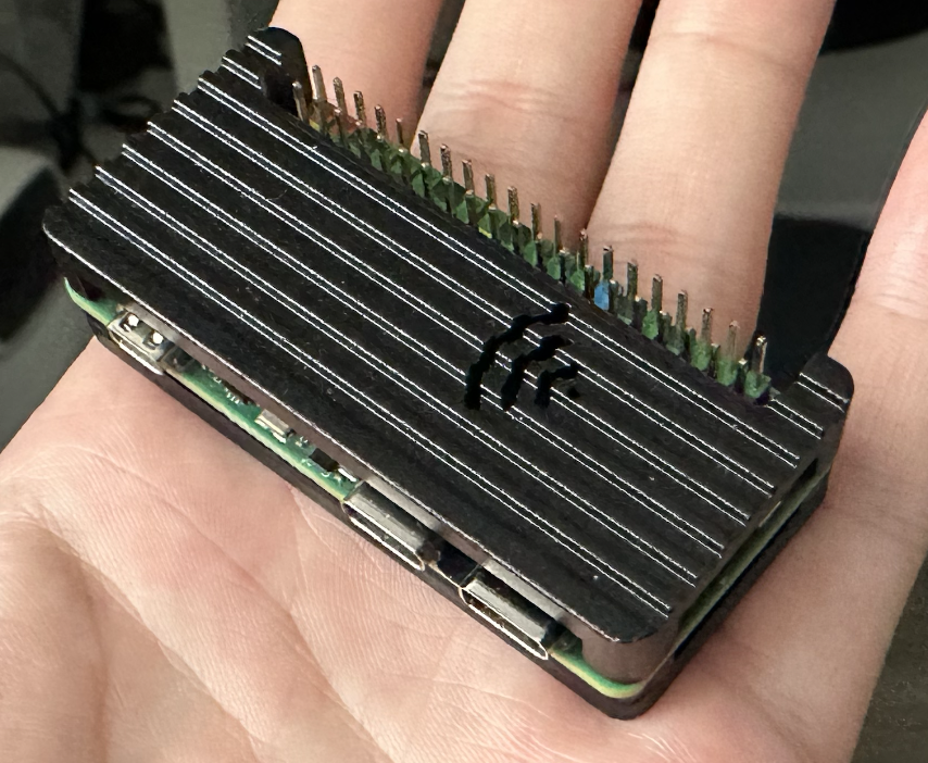
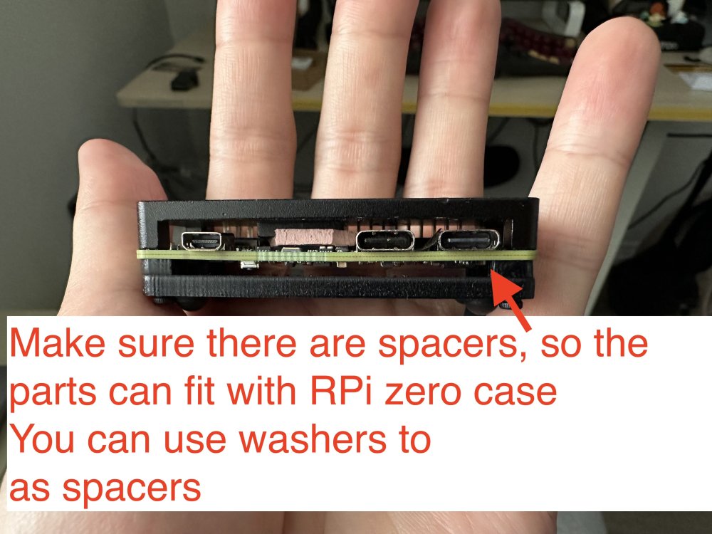
Oh, I do not have a nanopi r3s, and I do not plan to buy it. The image is for the radxa zero 3w, but as I provided the source of building it, you can customize it to build with nanopi, too. The reason I mentioned nanopi r3s is because it has a dedicated case for it. I ended up using raspberry pi zero case for it, with some custom modifications, which is also nice. Raspberry Pi 1/2/3, zero/zero w/zero w2 won't work, because they only have 1 USB controller. The trick here is to have at least 2 USB controllers: 1 in host mode to connect to the UAC2.0 speakers, and 1 in gadget mode as a UAC1.0 USB device. Raspberry Pi 4/5 should work, but you need to make sure the power supply is strong enough, which is a big issue here, because with the official image, you can only connect the USB C port for power and as a USB gadget port, yet PS5 probably won't support that much power for RPi 4/5, so you ended up needing a USB power and data splitter for that, and connect the data port to PS5, then a separate power supply for the power port (simliar things happened in PiKVM).
-
Hi, I learnt how to customize the image, and also found a simpler way to achieve the bootstrapping alsaloop. Here is the forked repository and a pre-built image for you to try. Supposedly, you just need to flash the image, and it should work out of the box. As the radxa zero 3w does not have the Ethernet port, so you will not accenditally connect it to some networking, I think it is fine to leave the root password as the default. However, if you plan to connect the device to some networking, remember to set up the root password. The Wifi is also working with the latest kernel release (my wifi module is broken, but I do see dmesg is trying to interact with that module).
-
I am thinking about getting a Nanopi R3S, which could be a better option, for it has a dedicated designed case for it. The CPU on it is the same one, so computation wise should be feasible.
-
Yes, absolutely works with the front USB. I do not know the regular price, that depends on the spec you choose (how much RAM, is eMMC included). I got the similar price for that board including shipping, but do note that it was shipped from China to Taiwan. Hmm, that's true for Hiby R3II, checking from the manual, it actually says:
-
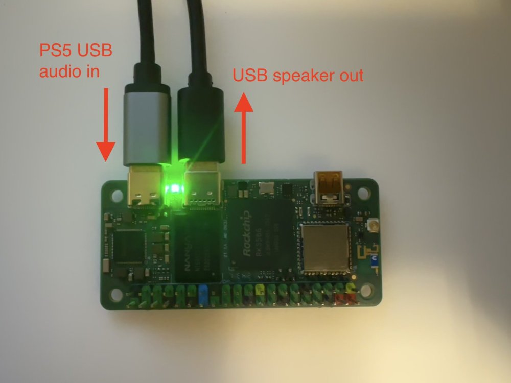
Hi, I would like to share my recent work: a cheap USB Audio Class 1.0 (UAC) input to UAC 2.0 output converter. For folks that may not understand why I have this crazy idea, here is the background: For some shitty reasons, PS5 does not support outputting audio through certain USB sound card, and that is because PS5 only supports very old USB sound card (UAC 1.0), and usually high end speakers or sound cards would use newer, better UAC 2.0 protocol. So, this shitty thing happens to me, when I thought my EDIFIER S880 speaker would be a plus for my gaming experience. EDIFIER S880 has a UAC 2.0 in input source, so my PS5 does not support that. So, what I can do is to use another 3.5 jack to connect the speaker to my PS5. Unfortunately, there is a staticky buzz sound throughout this channel. What's even worse is that EDIFIER S880 has 6 input source selection, but I can only switch to the next source, wait for 2 seconds, and repeat this process 5 times every time I want to switch the audio from my computer to the PS5. After lots of trials and flashing my custom kernel, I finally did it! The idea is to use a board that has 1 USB otg port to act as a UAC 1.0 sound card, and has another 1 USB host port to connect to the UAC 2.0 speakers, then run programs on that board to redirect sound from USB otg port to USB host port. It is even a plus that the board consumes less power, so we do not need an extra or special power supply for it; this becomes crucial, especially when sharing the same USB connection with the USB otg port (SBC boards are more power-hungry these days!). The standard USB 2.0 protocol only allows 5V 0.5A to the device connected. I actually built one with an Orange Pi One board, but it turns out that the CPU is not fast enough, and there are sound glitches sometimes. With some research, I found this board that perfectly fits my needs: Radxa zero 3W. Here is the advantage: - It is cheap, and the one I used is the nearly minimum SKU (1 GB ram with 8 GB onboard eMMC, they also have no onboard eMMC SKU). - The otg port could handle USB PD protocol, meaning no special hacks are needed, you could get at most 30W of power, if needed (and turns out the normal USB 2.0 port on my PS5 works perfectly, so I guess it consumes less than 5V 1A = 5W) - It is tiny. However, things don't work right out of the box. At the beginning, I flashed the official, latest Radxa OS, modprobe the g_audio. It is running as a UAC 2.0 device, so it is not the one I want. As a result, I grabbed their kernel source, changed the config to UAC 1.0 gadget, and flashed onto the board, but there seems to be some issues in their kernel fork for UAC 1.0 driver: there was no /dev/snd/controlC0, so the g_audio failed to run. As a result, I turned to use the Armbian build. This time, the /dev/snd/pcmC0D0c is missing, so g_audio failed to run again. I then compiled my own kernel, flashed it onto the board. The Armbian build is with kernel 6.1, and the kernel I built is kernel 6.12, then the board failed to boot to the kernel due to U-Boot thought there were some errors. Luckily, I found that building the whole Armbian image with kernel 6.12 can boot without issues, so I built a custom kernel 6.12 with UAC 1.0 enabled image, modeprobe the g_audio module, and it finally worked! After that, I crafted a simple golang SystemV daemon for bootstrapping and terminating the alsaloop program for redirecting the sound, and used a udev rule to notify that daemon of the attachment/detachment of the USB speaker out event. The converter is finally working! Here is the pre-built image for folks who want a quick test. It is based on the commit b27c86e620dcd9f55daadf52ccc85643dba2a381 from the armbian build repo with the following config modification: diff --git a/config/kernel/linux-rockchip64-current.config b/config/kernel/linux-rockchip64-current.config index d053d0997..6e360bba7 100644 --- a/config/kernel/linux-rockchip64-current.config +++ b/config/kernel/linux-rockchip64-current.config @@ -3507,3 +3507,8 @@ CONFIG_RATIONAL_KUNIT_TEST=m CONFIG_MEMCPY_KUNIT_TEST=m CONFIG_TEST_MEMCAT_P=m CONFIG_MEMTEST=y + +CONFIG_USB_CONFIGFS_F_UAC1=y +CONFIG_USB_CONFIGFS_F_UAC2=n +CONFIG_USB_F_UAC2=n +CONFIG_GADGET_UAC1=y Currently, the "current" build does not detect the Wi-Fi interface, but as it does not affect the audio converting feature, I may not put too much effort into this.
-
Hi all, I am new to kernel development, and I found an old ASUS tinkerboard. I want to give it a second life with some fun projects. The project I am building is another IP KVM, so I bought an HDMI to CSI module. After tinkering around for a while, I found I supplied the wrong clock for that module: [ 8.469299] tc358743 2-000f: unsupported refclk rate: 50000000 Hz [ 8.483069] kernel BUG at drivers/media/i2c/tc358743.c:593! I have no idea about the clock value to put in the dts file, so I just copied some values from the ASUS kernel source. From the driver code drivers/media/i2c/tc358743.c, it shows that there are only 3 valid clocks: switch (state->pdata.refclk_hz) { case 26000000: case 27000000: case 42000000: ... default: dev_err(dev, "unsupported refclk rate: %u Hz\n", state->pdata.refclk_hz); ... However, the clock values used in the dts file are some pre-defined macros: # dts configuration clocks = <&cru SCLK_VIP_OUT>; # include/dt-bindings/clock/rk3288-cru.h that contains the `SCLK_VIP_OUT` ... #define SCLK_CRYPTO 125 #define SCLK_MIPIDSI_24M 126 #define SCLK_VIP_OUT 127 ... I wonder if some folks have experience with the clock setting and can help me pick the correct value. Thank you.

