


SomeArmbianForumUser
-
Posts
28 -
Joined
-
Last visited
Content Type
Forums
Store
Crowdfunding
Applications
Events
Raffles
Community Map
Posts posted by SomeArmbianForumUser
-
-
The link to the krescue image on Armbian's Khadas-VIM3 page does not work (anymore). It needs to be replaced with https://dl.khadas.com/firmware/Krescue/dump/ (note the lower-case f in "/firmware/"). Confusingly, other firmware images are still available below https://dl.khadas.com/Firmware with upper-case F.
To prevent the image from getting lost again, I've asked the internet archive to archive the latest krescue sd card image for VIM3: https://web.archive.org/web/20240426161033/https://dl.khadas.com/firmware/Krescue/system/versions/VIM3.krescue.sd.220110_266.img.gz
-
MPD as installed by Armbian needs this audio_output configuration in /etc/mpd.conf in order to use the volume control of the on-board sound with Armbian mainline kernel 5.x on the BananaPi M1 (and maybe other A20 boards):
audio_output { type "alsa" name "BananaPi BuiltIn" device "hw:0,0" mixer_type "hardware" mixer_device "default" mixer_control "Power Amplifier" } -
BananaPi M1 with Armbian 21.02: How to Enable TV Output through the Composite Connector
A Banana Pi M1 set up as in the previous post, when connected to a display via
the composite connector, will display only early boot messages.When the linux kernel is started, the display at the composite connector will
go dark, and video will only be output through HDMI.To prevent this, blacklist the HDMI output module:
echo blacklist sun4i_drm_hdmi | sudo tee /etc/modprobe.d/composite.conf
However, in the current kernel, the HDMI output not compiled as a module, and therefore cannot be effectively blocked in this way.But it was compiled as a module in Armbian kernel version 5.8.6. Use
sudo armbian-config
to install this kernel version (under System -> Other) and reboot. The screen (console) will now show on the screen attached to the composite output.
Security-wise, changing to an older kernel is probably a bad move. For devices that need to access the internet, it may be better to recompile the current kernel instead after configuring that the above driver is compiled as a module. As this is not a concern for me, I have not tried this.
-
BananaPi M1 with Armbian 21.02: How to Enable Dallas One-Wire Temperature Sensor
The following step-by-step guide may be too detailed:
1) Write the Armbian image for Banana Pi to SD card.
xzcat <~/Downloads/Armbian_21.02.3_Bananapi_buster_current_5.10.21.img.xz | sudo dd of=/dev/mmcblk0 bs=1M
2) Set host name of the Banana Pi
Pop out SD card out of the laptop / PC and push back in.
# Replace occurrences of bananapi with desired hostname.sudo sed -i s/bananapi/test-w1/ /media/*/*f*/etc/host{s,name}
# umount sdcard, put in banana pi, Connect banana pi to network, power on3) SSH to Banana Pi and Configure 1Wire
ssh root@test-w1 # Follow instructions to change password and create user. Reconnect as user. sudo armbian-config # Navigate: System -> Hardware. Select w1-gpio. Save. Back. Reboot. # Reconnect after reboot as user. dmesg | grep wire [ 8.560693] Driver for 1-wire Dallas network protocol. [ 8.581436] gpio-271 (onewire@0): enforced open drain please flag it properly in DT/ACPI DSDT/board file [ 60.628063] w1_master_driver w1_bus_master1: Attaching one wire slave 00.800000000000 crc 8c cat /sys/kernel/debug/pinctrl/*/pinmux-pins Pinmux settings per pin Format: pin (name): ... ... pin 259 (PI3): (MUX UNCLAIMED) (GPIO UNCLAIMED) ... pin 271 (PI15): onewire@0 1c20800.pinctrl:271 function gpio_in group PI15 ...
GPIO 271 does not seem to be available on the GPIO header of the BananaPi.
For Linux, GPIO seem to either have a (high) number, or a name like PH8 or PI15.
I have only found one source that shows the location of these type of pin names on the
Banana Pi's GPIO Header: The table at the bottom of this page: http://www.elektronik-kompendium.de/sites/raspberry-pi/1907101.htmIf gives this mapping for the Banana Pi M1 GPIO Header to these names:
3V3 1 2 5V PB21 3 4 5V PB20 5 6 GND PI03 7 8 PH00 GND 9 10 PH01 PI19 11 12 PH02 PI18 13 14 GND PI17 15 16 PH20 3V3 17 18 PH21 PI12 19 20 GND PI13 21 22 PI16 PI11 23 24 PI10 GND 25 26 PI14
This shows that PI3 (which is the same as PI03) is available at pin 7.
In order to use this pin for one-wire, edit file /boot/armbianEnv.txt
on the banana pi. Add a line:param_w1_pin=PI3
Save and reboot. Connect a temperature sensor to 3V3, GND, pin 7, and a
suitable resistor. Then the temperature can be read bycat /sys/bus/w1/devices/w1_bus_master*/28-*/temperature -
I found that it is not easy to use the Dallas one-wire temperature sensors
and the composite TV-Out on the Banana Pi with the current Armbian version.I have searched for posts on these topics in the forum.
The posts that I have found in this forum describe solutions
for outdated Armbian versions or do not give enough detail. The
following posts in this thread will describe how to solve these problems for the current
Armbian version for the Banana Pi M1. -
Same problem here. Armbian Jessie on BananaPi
-
For more aggressive log rotation, I have now changed /etc/logrotate.d/rsyslog like this:
root@micro:~# diff /etc/logrotate.d/rsyslog{~,} -u --- /etc/logrotate.d/rsyslog~ 2017-01-18 23:14:38.000000000 +0100 +++ /etc/logrotate.d/rsyslog 2018-01-23 13:25:45.141409984 +0100 @@ -1,10 +1,9 @@ /var/log/syslog { - rotate 7 + rotate 4 daily missingok - notifempty - delaycompress + ifempty compress postrotate invoke-rc.d rsyslog rotate > /dev/null @@ -25,11 +24,10 @@ /var/log/messages { rotate 4 - weekly + daily missingok - notifempty + ifempty compress - delaycompress sharedscripts postrotate invoke-rc.d rsyslog rotate > /dev/nullAnd created a new logrotate file for openhab2:
root@micro:~# cat /etc/logrotate.d/openhab2 /var/log/openhab2/*.log { rotate 4 daily missingok ifempty compress postrotate service openhab2 restart endscript }Invoking these files with logrotate --force --verbose <filename> produces no error, and performs the expected operations.
If this works out in the long run, I can probably reduce the ramlog size back to 50MB.
-
I have now found
root@micro:~# find / -name log2ram* /etc/default/log2ramWhere I can increase the size of that file system.
I can still not upload armbianmonitor - seems like the armbian server has trouble:
root@micro:~# armbianmonitor -u System diagnosis information will now be uploaded to curl: (56) Recv failure: Connection reset by peer Please post the URL in the forum where you've been asked for. root@micro:~# armbianmonitor -u System diagnosis information will now be uploaded to <html> <head> <title>500 Internal Server Error</title> </head> <body> <h1>500 Internal Server Error</h1> The server has either erred or is incapable of performing the requested operation.<br /><br /> </body> </html>Please post the URL in the forum where you've been asked for. root@micro:~# armbianmonitor -u System diagnosis information will now be uploaded to <html> <head> <title>500 Internal Server Error</title> </head> <body> <h1>500 Internal Server Error</h1> The server has either erred or is incapable of performing the requested operation.<br /><br /> </body> </html>Please post the URL in the forum where you've been asked for.
I would still like advice how to increase the logrotate aggressiveness - delete old logs earlier, so they do not take as much space in ramlog.
-
Apparently, I can't:
root@micro:~# armbianmonitor -u System diagnosis information will now be uploaded to /usr/bin/armbianmonitor: line 374: [: -gt: unary operator expected /usr/bin/armbianmonitor: line 374: [: -gt: unary operator expected /usr/bin/armbianmonitor: line 374: [: -gt: unary operator expected /usr/bin/armbianmonitor: line 374: [: -gt: unary operator expected <html> <head> <title>500 Internal Server Error</title> </head> <body> <h1>500 Internal Server Error</h1> The server has either erred or is incapable of performing the requested operation.<br /><br /> </body> </html>Please post the URL in the forum where you've been asked for.
Interesting.
In the meantime I had deleted the largest file in /var/log, but this is not reflected in the output of df for the log2ram filesystem.
After the armbianmonitor error, I tried rebooting and manually unmounting /var/log in an attempt to maybe get armbianmonitor -u to work, but no success.
My openhab2 continues to run just fine on that device.
-
Thanks for Ramlog.
I have installed Armbian_5.35_Micro_Debian_stretch_next_4.13.16 and not done anything in terms of Ramlog setup.
What should I do when it is full? Or to avoid that it gets full?
Symptoms:
* Aptitude complained about "no space left on device" on exit.
* df:
root@micro:~# df -h Filesystem Size Used Avail Use% Mounted on udev 432M 0 432M 0% /dev tmpfs 100M 12M 89M 12% /run /dev/mmcblk0p1 29G 3.0G 26G 11% / tmpfs 499M 0 499M 0% /dev/shm tmpfs 5.0M 4.0K 5.0M 1% /run/lock tmpfs 499M 0 499M 0% /sys/fs/cgroup tmpfs 499M 36K 499M 1% /tmp log2ram 50M 50M 0 100% /var/log tmpfs 100M 0 100M 0% /run/user/0* usage:
root@micro:~# du /var/log/* | sort -n 0 /var/log/armhwinfo.log 0 /var/log/debug 0 /var/log/influxdb 0 /var/log/ntpstats 0 /var/log/sysstat 0 /var/log/user.log 4 /var/log/btmp 4 /var/log/debug.1 4 /var/log/kern.log 4 /var/log/messages 8 /var/log/aptitude 8 /var/log/auth.log 8 /var/log/unattended-upgrades 24 /var/log/faillog 28 /var/log/wtmp 36 /var/log/user.log.1 44 /var/log/alternatives.log 48 /var/log/armhwinfo.log.1.gz 52 /var/log/syslog.3.gz 60 /var/log/bootstrap.log 136 /var/log/auth.log.1 140 /var/log/apt 160 /var/log/kern.log.1 192 /var/log/messages.1 248 /var/log/syslog.2.gz 288 /var/log/lastlog 348 /var/log/dpkg.log 3060 /var/log/daemon.log 3092 /var/log/syslog 10208 /var/log/openhab2 14912 /var/log/syslog.1 18084 /var/log/daemon.log.1I know that openHAB2 is causing the majority of the log messages. That's the purpose of that computer.
How can I increase the amount of RAM used for Ramlog, or make the log rotation more aggressive?
-
Why are you messing with wpa_supplicant when you were already "able to connect to [your] wifi AP using nmtui, and now [you're] trying to share the internet with any device that is connected in eth0 ...".
In the simplest realization this would just need a static private IP address for eth0, ip forwarding, a NAT iptables rule, static addresses, routes, and dns settings on the connected devices.
You say you are tired from trying out so many things but you do not describe what went wrong in even a single try.
-
I needed small devices able to run a linux daemon and control a bluetooth LE device. They are used as antennas in a bluetooth mesh network. The orange pi zero seemed to be a good choice.
Why choose the orange pi zero for this? It does not have bluetooth on board.
-
Perhaps this reddit post will help you: https://www.reddit.com/r/linux4noobs/comments/32cx8b/linux_entropy_hostapd/
That link says "an encrypted wireless network requires entropy". That's understood. No questions about that.
You have suggested that also my unencrypted example network from post 13 requires entropy. Could you please explain why?
Actually I see a rise in available entropy from the start of hostapd. That alone does not contradict your suggestion, as there might be an entropy valley during the start that I do not detect with my before and after measurements.
-
It appears to me that your system does not have enough entropy generated to establish a secure connection for the access point. The reason your "workaround" seems to work is because it helps create entropy.
I am surprised that an unencrypted, open wireless network (cf post #13) needs entropy. Why is that?
-
I've updated the wiki with instructions to remove the resistors and a photo highlighting their location on the PCB.
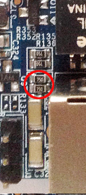
You have made the same mistake graphically that I made physically at first. Sorry for not being clear enough.
In that picture, you have actually encircled R353/R352. These are _not_ identical to R135/R136. R135/R136 sit directly below the encircled resistors in that picture. R353/R352 can stay, R135/R136 have to go.
A correctly modified board looks like this (test if I can include images from the sunxi wiki):
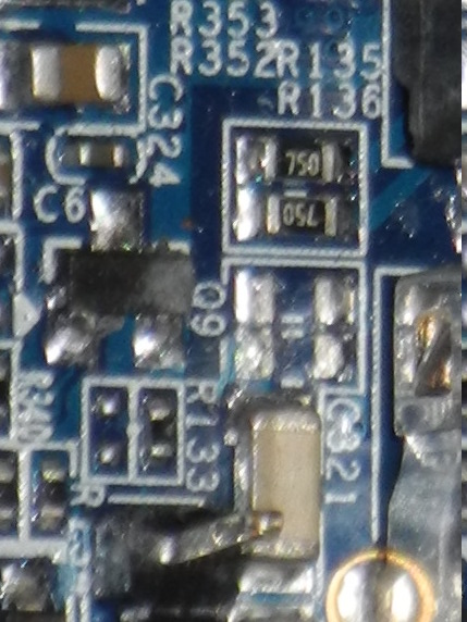
I have now corrected the wiki page. I could not replace the image with the wrong resistors highlighted, so I uploaded a new one with a different name and used this in the article to highlight the R135/R136 resistor positions:
-
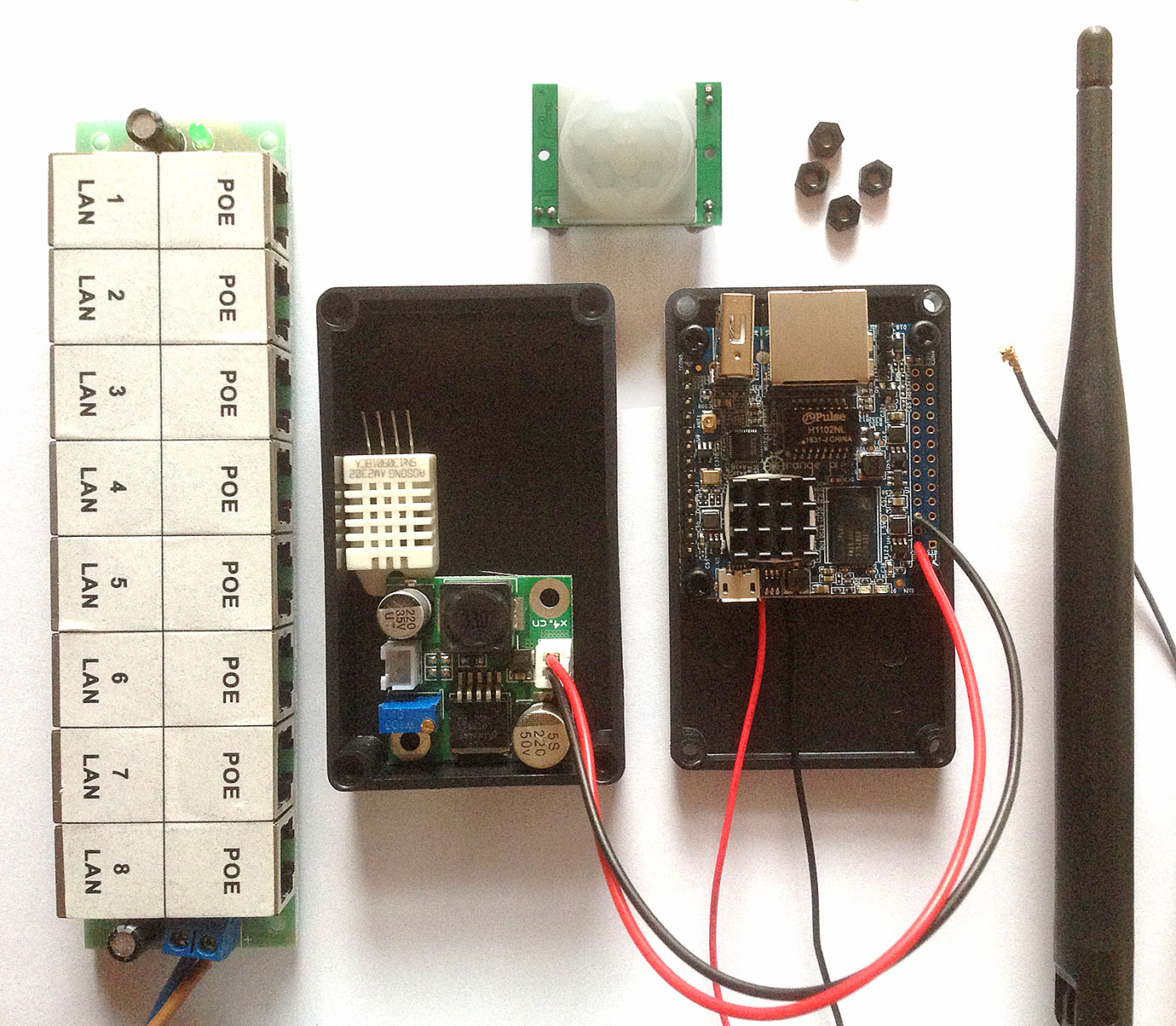
Success: My First OPZ runs on PoE.
I have used this PoE Injector, extended it with this fuse holder, currently it contains a 200mA slow acting fuse. I'm using this 24V 0.5A power supply and these buck converters. I would not recommend the buck converters, because they are very tricky to adjust.
-
So I guess Xunlong never tested this
To be fair, the HW manufacturer planned for direct 5V injection, which would only produce 166mW wasted heat through these resistors. Armbians suggested a more practical aproach with higher network voltage and a buck converter, for which I'm thankful.
-
It seems that I'm the first person (*) to actually tinker with passive PoE on the Orange Pi Zero. I'm not finished yet, but I'd like to publish this warning for the benefit of anyone who follows on this path:
Before you inject power over ethernet, remove resistors R135 and R136 from the Orange Pi Zero board!
These resistors can be found on the top side of the board, next to the RJ45 jack:
(Apparently I'm not allowed to post images. Be sure to remove the correct ones. the resistors nearest the label "R135/R136"l are actually R353/R352. R135/136 are nearer to the RJ45 connector. Yes I found out by removing the wrong ones first.)
If these resistors are left on the board, they will connect POE+ and POE-GND with a resistance of 150Ω. At 24V, that would produce 3.8W of heat. These resistors would not sustain that. I found out something's wrong in the good old tradition of connecting power and see if smoke develops.
Then I cut them off with small wire cutters (I suck at SMD soldering).
(*) The image at http://linux-sunxi.org/images/c/c1/OPi_Zero_preparing_Access_Point.jpg also shows PoE preparations, but apparently it has not actually been used with PoE power, as you can see R135 still intact, and the part of R136 that can bee seen also shows no damage.
-
a. Can the Kernel and application be transferred to RAMFS on first boot ?
What's the point? Once started, they are in RAM anyway.
-
Need to compare with all existing records
This looks like a bottleneck. Define "all".
16 bytes every half second will fill up 512 MB RAM in a approx. half a year. Not taking into account overhead, compression, other processes that use RAM.
You should plan for a maximum measurement duration significantly lower than that. And check the performance of your DAQ system for the end of the planned measurement period, i.e. with a large set of simulated data already in memory.
-
The orange pi zero has a USB OTG interface, which can be used to interact with it in the absence of networks and spare USB-UART converters.
This is not enabled by default in the Armbian image.
Here I describe how to modify the system image before first boot to enable this.
- First, mount the freshly written SD card on a linux computer,
- become root, and
- change directory to the mount point, that is, the root directory of the SD card.
The following couple of steps were taken from https://oshlab.com/enable-g_serial-usb-otg-console-orange-pi-armbian/which describes how to enable this in a live system, i.e. after first boot. The steps are modified to work on the mounted SD card image. Basically, the first slash before etc is removed.
- echo "g_serial" >>etc/modules
- echo "ttyGS0" >>etc/securetty
- mkdir etc/systemd/system/serial-getty@ttyGS0.service.d
- Create new file etc/systemd/system/serial-getty@ttyGS0.service.d/10-switch-role.conf with contents
[Service] ExecStartPre=-/bin/sh -c "echo 2 > /sys/bus/platform/devices/sunxi_usb_udc/otg_role"
The guide for the live system then calls systemctl enable which you cannot do here since the system to be modified is not running and you can also not chroot into it because of the ARM architecture. Instead, duplicate that command's effect by creating a symlink:- ln -s /lib/systemd/system/serial-getty@.service etc/systemd/system/getty.target.wants/serial-getty@ttyGS0.service
Note there is a slash before lib, but again no slash before etc.Now unmount the sd card, insert into the orangepizero, power it from a USB port of your computer, or, to be safe, put a powered USB hub between your computer and the orangepizero.Wait for the orangepizero to cycle through its first automatic reboot. You can recognize the reboot by the simultaneous flashing of the RJ45 LEDs.Now you can establish the serial connection withscreen /dev/ttyACM0 115200
and login as root from there.
May also work for other boards with USB OTG.
-
Serial console (using Micro USB or the pin header) is mandatory. This way you can do a clean shutdown and then the interesting stuff gets into the logs.
USB keyboard should also work, as there is a getty on tty1: connect keyboard, type
root <password> poweroff
with some pauses to allow the system to react. No display needed.
(regarding micro-USB: g_serial and agetty for the micro-USB are not configured in the armbian image as shipped).
-
Safety
I'm considering passive PoE for 2 to 4 Opi0 distributed across our house.
I want to make sure the house cannot burn down even if something shorts the power supply lines at the remote network socket or if the cat6 installation cable is damaged.
The linked 8 port passive PoE injector does not mention fuses in its description.
This 4 port injector https://www.amazon.com/WEONE-Ethernet-Injector-Ausr%C3%BCstung-IP-Kamera-CAT-5-6/dp/B01HPLCLGM/mentions a "resettable 650 mA fuse" for each port. I ask myself if 650mA is low enough for safety, and if this ability to reset itself is not risky.
I guess I should add an additional external fuse between power supply and PoE injector that is even lower for peace of mind. 4 Opi0s, with IoT power saving settings but both network interfaces active, might consume 3 Watt total. With 90% efficiency of the buck converters I would need 3.3 Watts total at the 4 remote network sockets, Wikipedia tells me PoE specs assume ~25% conduction loss, so I would need to inject 4.2 Watts total into the central patch panel, which at 24 Volts means total current for 4 Opi0s should not exceed 175mA.
If I use a single external 200mA quick melting fuse for a four port injector I should have enough power to drive 4 Opi0s and still have headroom for spikes. My cat6 installation length is < 20m everywhere. With the normally low currents of the Opi0s, conduction loss should be lower than the 25% rule of thumb for PoE.
Please point out any flaws I made. I'm a bit paranoid here.
-
Suffering from over-scanning(?)
How can adjust or disable it.
Workaround: https://bbs.nextthing.co/t/how-to-use-text-mode-linux-console-tty1-over-composite/11308
Configuring MPD audio_output on Allwinner A20 (BananaPi M1)
in Reviews, Tutorials, Hardware hacks
Posted
Update for current kernels (running linux 6.6.31 now): device and mixer_device need to change:
audio_output {
    type        "alsa"
    name        "BananaPi BuiltIn"
    device        "hw:1,0"
    mixer_type      "hardware"
    mixer_device    "hw:1"
    mixer_control    "Power Amplifier"
}
Or to (hopefully) protect from future renumberings:
audio_output {
    type        "alsa"
    name        "BananaPi BuiltIn"
    device        "hw:CARD=sun4icodec,DEV=0"
    mixer_type      "hardware"
    mixer_device    "hw:sun4icodec"
    mixer_control    "Power Amplifier"
}
See here for explanation of the device names to use in mpd with alsa: https://github.com/MusicPlayerDaemon/MPD/issues/374#issuecomment-432663715