

nkahl
-
Posts
12 -
Joined
-
Last visited
Content Type
Forums
Store
Crowdfunding
Applications
Events
Raffles
Community Map
Posts posted by nkahl
-
-
Hello all,
sorry for dropping in here.
My tutorial at https://forum.armbian.com/index.php?/topic/4040-enable-1-wire-in-kernel-49-on-bananapi/ contained some errors. These are fixed now, please check it again, it should work.
")
Sorry for the trouble.
Best regards,
Norbert Kahl
-
Sorry for all the rush. It was the length of the cable (> 2 metres) which caused this error, since pull-up resistors and terminators are required at that length. Just another I2C-Newbie...
When using jumper wire (~ 20cm), it works, the LCD display appears as 0x27 on I2C-1.
Thanks for all the help!
Best regards,
Norbert Kahl
-
I am using a "normal" Banana Pi, not a Pro or M2 model.
There are two I2C-busses here:
root@bpi:/dev# ls /dev/i2c-*
/dev/i2c-0  /dev/i2c-1
On the 0-bus, there is "something" detected but I guess it belongs to the system or internal hardware, not to the display:
     0  1  2  3  4  5  6  7  8  9  a  b  c  d  e  f
00:          -- -- -- -- -- -- -- -- -- -- -- -- --
10: -- -- -- -- -- -- -- -- -- -- -- -- -- -- -- --
20: -- -- -- -- -- -- -- -- -- -- -- -- -- -- -- --
30: -- -- -- -- UU -- -- -- -- -- -- -- -- -- -- --
40: -- -- -- -- -- -- -- -- -- -- -- -- -- -- -- --
50: -- -- -- -- -- -- -- -- -- -- -- -- -- -- -- --
60: -- -- -- -- -- -- -- -- -- -- -- -- -- -- -- --
70: -- -- -- -- -- -- -- --
The 1-bus is just blank.

-
Hello,
I have a 4x20 LCD display (with an HD44780 compatible adaptor) connected to my Banana Pi. It is running (freshly installed, switched from Bananian) on the mainline kernel:
Linux bpi 4.9.7-sunxi #1 SMP Thu Feb 2 01:52:06 CET 2017 armv7l GNU/LinuxHowever, the display is not recognized. I checked the wire connections multiple times, they're okay and the backlight is on.
So I assume this is a software issue. The output of "i2cdetect -y 1" is:
     0  1  2  3  4  5  6  7  8  9  a  b  c  d  e  f
00:          -- -- -- -- -- -- -- -- -- -- -- -- --
10: -- -- -- -- -- -- -- -- -- -- -- -- -- -- -- --
20: -- -- -- -- -- -- -- -- -- -- -- -- -- -- -- --
30: -- -- -- -- -- -- -- -- -- -- -- -- -- -- -- --
40: -- -- -- -- -- -- -- -- -- -- -- -- -- -- -- --
50: -- -- -- -- -- -- -- -- -- -- -- -- -- -- -- --
60: -- -- -- -- -- -- -- -- -- -- -- -- -- -- -- --
70: -- -- -- -- -- -- -- --
which leads me to the consideration that it is not even recognized by the system.
I did the following things - without success:
- run "apt-get dist-upgrade" (where some 404 errors occured, see this topic for details)
- installed "i2c-tools" and "python-smbus"
- loaded "i2c-dev" kernel module
According to the documentation https://docs.armbian.com/Hardware_Allwinner/#connect-your-lcd-display, the I2C stuff should work out of the box in the mainline kernel.
Any help would be appreciated.
Best regards and thanks in advance,
Norbert Kahl
-
Hmmmm, something similar is happening here for the main armbian repository:
Get:1 https://apt.armbian.com/ jessie/main linux-dtb-next-sunxi armhf 5.27.170427 [150 kB]
Err https://apt.armbian.com/ jessie/main linux-dtb-next-sunxi armhf 5.27.170427
  HttpError404
Get:2 https://apt.armbian.com/ jessie/main linux-image-next-sunxi armhf 5.27.170427 [15.9 MB]
Err https://apt.armbian.com/ jessie/main linux-image-next-sunxi armhf 5.27.170427
  HttpError404
E: Failed to fetch https://apt.armbian.com/pool/main/l/linux-4.10.12-sunxi/linux-dtb-next-sunxi_5.27.170427_armhf.deb HttpError404 E: Failed to fetch https://apt.armbian.com/pool/main/l/linux-4.10.12-sunxi/linux-image-next-sunxi_5.27.170427_armhf.deb HttpError404However, this seems to be limited to the two packages "linux-dtb-next-sunxi" and "linux-image-next-sunxi". Not sure if this breaks anything (currently having I2C troubles, but probably they're not related to this). -
Hello all,
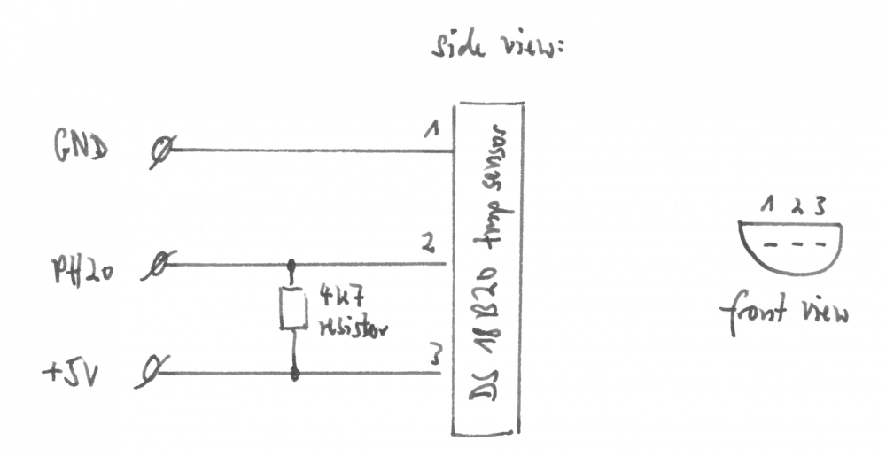
of the occasion now comes a tutorial for how to set up a DS18B20 temperature sensor on a Banana Pi:
- Connect the sensor and a 4k7 pull-up resistor as shown in the attached circuit diagram. Make sure the Banana Pi is switched off to avoid any damage.
- Boot the BPi and log in as "root".
-
Create a new directory in the root's home and copy the Banana Pi device tree (DTB) to it:
mkdir dtb
cp /boot/dtb/sun7i-a20-bananapi.dtb .
cd dtb/
Change to the new directory with the cd command.
-
Decompile the DTB:
dtc -I dtb -O dts sun7i-a20-bananapi.dtb > sun7i-a20-bananapi.dts -
Open the DTS file (which contains plaintext and is thereof human-readable), for example, with nano.
-
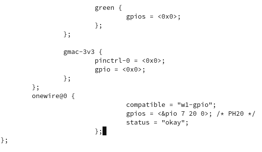
Insert the following code block at the end of the file before the last line (containing };) - see attached screenshot if necessary:
onewire@0 { compatible = "w1-gpio"; gpios = <&pio 7 20 0>; /* PH20 */ status = "okay"; }; -
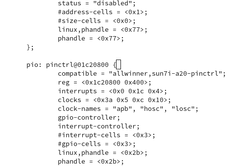
Search for "pinctrl@01c20800" in the file and go to it.
-
Put a "pio: " before "pinctrl@01c20800" (see screenshot).
-
Save your changes and exit the DTS file.
-
Run the following commands:
mv sun7i-a20-bananapi.dtb sun7i-a20-bananapi.dtb.orig
dtc -I dts -O dtb sun7i-a20-bananapi.dts > sun7i-a20-bananapi.dtb
cp sun7i-a20-bananapi.dtb /boot/dtb/sun7i-a20-bananapi.dtb
sync
shutdown -r now
This will move the original DTB file to "sun7i-a20-bananapi.dtb.orig" (in case you need it in the future), compile the DTS file to a new DTB and copy this into /boot. Then your Banana Pi is restarted.
-
Afterwards, the temperature sensor will show up in /sys/bus/w1/devices with a random ID.
-
The temperature can be read out via:
cat /sys/bus/w1/devices/[DS18B20 ID]/w1_slaveReplace [DS18B20 ID] with the ID you see in the directory, it is usually beginning with "28-". The command's output will contain something like
t=20312which is the temperature in Celsius (°C), here, it is ~ 20,3 °C.
This tutorial assumes that the sensor is connected to the PH20 pin, if you use another, you will need to edit the code snippets above.
Kudos to zador.blood.stained for all the help!
Further readings:
- https://linux-sunxi.org/1-Wire
- https://www.cl.cam.ac.uk/projects/raspberrypi/tutorials/temperature/
- http://www.linuxx.eu/2014/09/banana-pi-temperature-sensor-ds18b20.html
Best regards,
Norbert Kahl
-
Thanks for the hint. I did this already, but there is no "pio"-section. Must I add it manually?
-
My decompiled DTS file now looks like this:
/dts-v1/;

/ {
	compatible = "allwinner,sun7i-a20";

	fragment@0 {
		target = <0xffffffff>;

		__overlay__ {

			w1_pins: w1_pins {
				allwinner,pins = "PH20"; // use PH20 pin for 1-Wire
				allwinner,function = "gpio_in";
				alwinner,pull = <0>;
				linux,phandle = <0x1>;
				phandle = <0x1>;
			};
		};
	};

	fragment@1 {
		target-path = [2f 00];

		__overlay__ {

			w1: onewire@0 {
				compatible = "w1-gpio";
				pinctrl-names = "default";
				pinctrl-0 = <&w1_pins>;
				gpios = <&pio 7 20 0>; // PH20 seems to be "7 20", "3" belongs to different GPIO header
				status = "okay";
			};
		};
	};

	__symbols__ {
		w1_pins = "/fragment@0/__overlay__/w1_pins";
	};

	__fixups__ {
		pio = "/fragment@0:target:0", "/fragment@1/__overlay__/onewire@0:gpios:0";
	};

	__local_fixups__ {

		fragment@1 {

			__overlay__ {

				onewire@0 {
					pinctrl-0 = <0x0>;
				};
			};
		};
	};
};
And it won't compile:
root@bpi:~/own_dtb# dtc -I dts -O dtb sun7i-a20-w1-gpio.dts > sun7i-a20-w1-gpio.dtbo
ERROR (phandle_references): Reference to non-existent node or label "pio"

ERROR: Input tree has errors, aborting (use -f to force output)
Could somebody who got this 1-wire sensor stuff working just post his/her dts file?
-
Nope, this doesn't work. I am now trying to do this:
On 4/16/2017 at 2:43 PM, martinayotte said:You first need to decompile DTB into DTS and you need to add some thing like that in you DTS in PIO section :
                        w1_pins: w1_pins {
                                allwinner,pins = "PD14";
                                allwinner,function = "gpio_in"; // in (initially)
                                allwinner,pull = <0>; // off
                        };
Then, at the root level :
                        w1: onewire@0 {
                                compatible = "w1-gpio";
                                pinctrl-names = "default";
                                pinctrl-0 = <&w1_pins>;
                                gpios = <&pio 3 14 0>; // PD14
                                status = "okay";
                        };
Although it does not became clear to me where exactly the code snippets must be copied to.
-
Hello,
thanks for your reply and the information.
What puzzles me is that there seems to be a w1-gpio overlay in /boot/dtb/overlays/ which looks - decompiled
- quite good. However, it uses the "PI15" pin which does not exist on Banana Pi.
I try to change the used pin, since I don't know where to copy the code blocks mentioned by martinayotte on Apr. 16th.
Any results will be reported here.
Best regards,
Norbert Kahl
-
Hello all,
sorry for dropping in here.
I am trying to access a DS18B20 temperature sensor on my Banana Pi, which is runnin on the mainline kernel:
Linux bpi 4.10.12-sunxi #7 SMP Wed Apr 26 02:44:12 CEST 2017 armv7l GNU/LinuxHowever, I cannot get the sensor working. What I've tried so far is:
-
Edit the /boot/script.bin file via sunxi-tools, as described multiple times on the net. Adding lines such as
[w1_para]
gpio = 4
has no effect at all. (As mentioned above, this method is not used anymore - thanks for the hint!
)
-
Editing the /boot/armbianEnv.txt is not working either:
-
Adding
overlays=w1-gpiohas no effect at all.
-
Adding
overlays=sun7i-a20-w1-gpio(while sun7i-a20-w1-gpio[.dtbo] is the filename of the DTB-tree in /boot/dtb/overlays/) causes some entries show up in /sys/bus/w1/devices/. They seem to be random, since the IDs are changing after a minute or so, and cannot be accessed.
-
Adding
Further, the kernel modules w1_gpio and w1_term are loaded during boot, which seems to have no effect, either.
Using the 2.2 method, lines like these
[   62.195492] w1_master_driver w1_bus_master1: Family 0 for 00.800000000000.8c is not registered.
[  125.795516] w1_master_driver w1_bus_master1: Family 0 for 00.400000000000.46 is not registered.
[  176.555608] w1_master_driver w1_bus_master1: Family 0 for 00.c00000000000.ca is not registered.
[  252.995466] w1_master_driver w1_bus_master1: Family 0 for 00.200000000000.23 is not registered.
[  316.595477] w1_master_driver w1_bus_master1: Family 0 for 00.a00000000000.af is not registered.
[  354.516052] w1_master_driver w1_bus_master1: Family 0 for 00.600000000000.65 is not registered.
[  394.995595] w1_master_driver w1_bus_master1: Family 0 for 00.e00000000000.e9 is not registered.
[  457.995555] w1_master_driver w1_bus_master1: Family 0 for 00.100000000000.9d is not registered.
[  497.115573] w1_master_driver w1_bus_master1: Family 0 for 00.900000000000.11 is not registered.
[  572.355679] w1_master_driver w1_bus_master1: Family 0 for 00.500000000000.db is not registered.
are showing up in dmesg.
The system is not upgraded from an older version but freshly installed (two days ago, switching from Bananian). DS18B20 is correctly plugged in with a 4k7 resistor, checked this multiple times.
Any help is greatly appreciated (forgive me if I made a trivial mistake).
Best regards,
Norbert Kahl
-
Edit the /boot/script.bin file via sunxi-tools, as described multiple times on the net. Adding lines such as

4x20 I2C LCD display (HD44780) with Banana Pi not working
in Allwinner sunxi
Posted
Yep, and with the pull-up resistors, everything works fine now.