mhel
Members-
Posts
13 -
Joined
-
Last visited
Recent Profile Visitors
The recent visitors block is disabled and is not being shown to other users.
-
@kalekulan I had the same. When I upgraded emmc can't boot anymore. It doesn't get detected when plugged to usb by itself. SD card still works tho you can try to force boot it. Put the jumper on the mask rom mode, and place a bootable sdcard, then plugged it to USB. It might help if you can monitor the serial port. The sdcard will boot but it will detect the eMMC mode and the eMMC will be detected by the pc. Then you can do the usual dd'ing. EDIT: with the eMMC booting now, it still don't get detected by the pc when you plug it in, but atleast it boot now. And somehow it just shutdown on me just now, over temperature. only got mariadb and freeradius running on it. My tiny rpi copper heatsink is most likely no enough.
-
Yeah, it's the S version that I have. Wha'ts puzzling about it is, the same image file loaded to the sdcard works. Edit: It's working now again, I dd'd the image this time. last time I used balena etcher. There must be something different with how it write image file. Thanks for the continuous support of this aging board.
-
I have the same problem, I had it working for a year. Yesterday I decided to upgrade and I thought I burned the board. Luckily the SD-card still works. @Scott Picton I tried your fix didn't work for me. I forced boot the board with the sdcard in it but with the jumper on for eMMC. and tried to dd the .spl, but nothing changed. did you dd the .spl from the same image of the latest released? or from an older release?
-
Got it to work 🙂 I'm not exactly sure what fixed it but I'll probably figure it out once it breaks again. this is my new overlay so others may find it useful. /dts-v1/; /plugin/; / { compatible = "allwinner,sun4i-a10", "allwinner,sun7i-a20", "allwinner,sun8i-h3", "allwinner,sun50i-a64", "allwinner,sun50i-h5"; fragmen@0 { target = <&pio>; __overlay__ { display_pins: display_pins { pins = "PA3", "PA6"; function = "gpio_out"; }; }; }; fragment@1 { target = <&spi0>; __overlay__ { /* needed to avoid dtc warning */ #address-cells = <1>; #size-cells = <0>; display: display@0 { compatible = "adafruit,yx240qv29", "ilitek,ili9341"; reg = <0>; pinctrl-names = "default"; pinctrl-0 = <&display_pins>; spi-max-frequency = <16000000>; rotation= <270>; bgr; fps = <10>; buswidth = <8>; height = <240>; width = <320>; reset-gpios = <&pio 0 6 0>; /* GPIOA 6 */ dc-gpios = <&pio 0 3 0>; /* GPIOA 3 */ debug = <3>; }; }; }; __overrides__ { rotation = <&display>, "rotation:0"; fps = <&display>, "fps:0"; debug = <&display>, "debug:0"; }; };
-
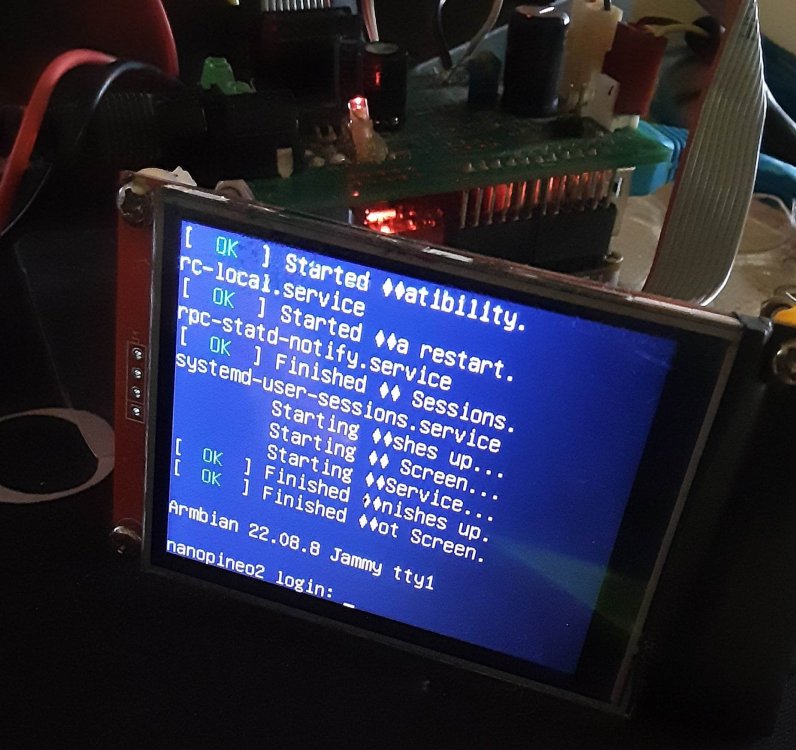
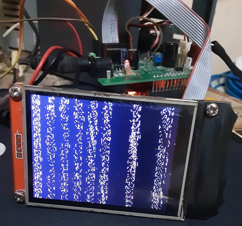
Hi, I finally have time to get back to my little project. I've been trying to get a working display with tinydrm for an ILI9341 base lcd. My setup works on OpenWrt with the older fbtft driver, but now I'd like to go back and try Armbian (current release is Jammy) on it. My first try with devicetree overlay seems functional but not correct. The display just show garbled data (see attached). What could be the problem with it? This is my env. verbosity=1 bootlogo=false console=both overlay_prefix=sun50i-h5 overlays=usbhost1 usbhost2 spi-spidev param_spidev_spi_bus=0 rootdev=UUID=e0ed80c4-a252-4d96-ad61-78b7834d6b8d rootfstype=ext4 user_overlays=spilcd usbstoragequirks=0x2537:0x1066:u,0x2537:0x1068:u and this is my overlay /dts-v1/; /plugin/; / { compatible = "allwinner,sun4i-a10", "allwinner,sun7i-a20", "allwinner,sun8i-h3", "allwinner,sun50i-a64", "allwinner,sun50i-h5"; fragment@0 { target = <&spi0>; __overlay__ { #address-cells = <1>; #size-cells = <0>; display: display@0 { compatible = "adafruit,yx240qv29", "ilitek,ili9341"; reg = <0>; rotation = <270>; reset-gpios = <&pio 0 6 0>; /* GPIOA 6 */ dc-gpios = <&pio 0 3 0>; /* GPIOA 3 */ }; }; }; };
-
You would have to check first if you kernel modules has the fbtft modules built (most of the fbtft modules are in the staging). The configuration is in "Support for small TFT LCD display modules" in staging. Second you have to check if in that modules your LCD display controller has a driver, but Waveshare doesn't mention it's display controller. I have a 2.8" spi LCD with ILI9341 controller working on a nanopi neo2, the driver is already in the staging for ILI93141 it just have to be enabled. You may have to build your own kernel if the modules are not built.
-
https://linux-sunxi.org/images/4/4b/Allwinner_H3_Datasheet_V1.2.pdf Looks like it's not 5v tolerant.
-
So your dts files appear to have this: leds { compatible = "gpio-leds"; status { label = "nanopi:blue:status"; gpios = <&pio 0 10 GPIO_ACTIVE_HIGH>; linux,default-trigger = "heartbeat"; }; pwr { label = "nanopi:green:pwr"; gpios = <&r_pio 0 10 GPIO_ACTIVE_HIGH>; default-state = "on"; }; }; So you have to do it like gpios = <&pio 3 7 0>; // gpio3 pin 7 active_high or maybe 1 for active high.
-
You can use whatever gpio is available. And you can group it with your leds. leds { compatible = "gpio-leds"; pwr { label = "nanopi:red:pwr"; gpios = <0x38 0x00 0x0a 0x00>; linux,default-trigger = "default-on"; }; status { label = "nanopi:green:status"; gpios = <0x0c 0x00 0x0a 0x00>; linux,default-trigger = "heartbeat"; }; ledBoot { label = "just_a_name"; linux,default-trigger = "default-on"; default-state = "on"; gpios = <3 7 0 0>; // Gpio3 pin 7 ? ? }; }; Whatever gpio is available for you. If you use a gpio not used anywhere, you won't brick your board. Why did you have to decompile the dtb? if the source is available for your board then you can look for the dts file an you can see how the gpios are defined.
-
I'm not sure what device you have, but on the board I have this is used on the device tree leds { compatible = "gpio-leds"; user_led: led-1 { label = "ctf-blue"; linux,default-trigger = "default-on"; default-state = "on"; gpios = <&gpio2 RK_PB0 1>; }; }; and lights up the led as it boot, it's not an activity led tho.
-
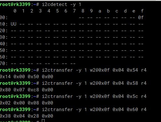
Hello, I'm attempting to port an unknown rk3399 board to Linux from Android with kernerl 4.4. I managed to extract the devicetree and it's slowly coming along with poking arround and mixing and matching and comparing devicetrees (it's not easy but I got time ;-) ) The board uses a tc358775 converter for the lvds display since the rk3399 doesn't have one built in. With patch from here: https://forum.armbian.com/topic/16747-orange-pi-4-kernel-510y-mipi-dsi-panel-sucessful/ it started to show some signs of life. The screen is lighting up seems to have activities but it's just showing bars. I'm not sure if it's a timing issues, but I used the exact values from extracted dtb, another I'm not sure are the dsi/panel properties from old dtb if useable on my reconstructed devicetree. I'm testing this on mainline 5.14, I tried on 5.10.y but I can't get it to show activities only flashing RGB colours. Now, there's actually a driver for the converter, but I can't figure out how to use it yet, so I'm sticking with the simple panel. If anyone could point me in the right direction that would be great. Here's my dsi tree: &mipi_dsi { status = "okay"; ports { #address-cells = <1>; #size-cells = <0>; mipi_out: port@1 { reg = <1>; mipi_out_panel: endpoint { remote-endpoint = <&panel_in_mipi>; }; }; }; lcd_panel: panel@0 { compatible = "panel-dsi-simple"; reg = <0>; backlight = <&backlight>; power-supply = <&vcc_lcd>; enable-delay-ms = <100>; enable-gpios = <&gpio1 RK_PC2 GPIO_ACTIVE_HIGH>; reset-gpios = <&gpio1 RK_PD0 GPIO_ACTIVE_HIGH>; /* prepare-delay-ms = <100>; reset-delay-ms = <20>; */ dsi,flags = <0xa03>; dsi,format = <0>; dsi,lanes = <4>; rockchip,lane-rate = <890>; panel-init-sequence = [ 29 02 06 14 01 07 00 00 00 29 02 06 3c 01 0b 00 08 00 29 02 06 64 01 0e 00 00 00 29 02 06 68 01 0e 00 00 00 29 02 06 6c 01 0e 00 00 00 29 02 06 70 01 0e 00 00 00 29 02 06 34 01 1f 00 00 00 29 02 06 10 02 1f 00 00 00 29 02 06 04 01 01 00 00 00 29 02 06 04 02 01 00 00 00 29 02 06 50 04 30 01 f0 03 29 02 06 54 04 14 00 50 00 // hsync-len, hback-porch // 04 54 00 50 00 14 29 02 06 58 04 80 07 c8 00 // hfront-porch, hactive // 04 58 00 c8 07 80 29 02 06 5c 04 02 00 08 00 // 04 5c 00 08 00 02 // vback-porch, vsync-len 29 02 06 60 04 38 04 28 00 // 04 60 00 28 04 38 // vfront-porch, vactive 29 02 06 64 04 01 00 00 00 29 02 06 a0 04 06 80 44 00 29 02 06 a0 04 06 80 04 00 29 02 06 04 05 04 00 00 00 29 02 06 80 04 00 02 02 03 29 02 06 84 04 04 07 05 08 29 02 06 88 04 09 0a 0e 0f 29 02 06 8c 04 0b 0c 0d 10 29 02 06 90 04 16 17 11 12 29 02 06 94 04 13 14 15 1b 29 02 06 98 04 18 19 1a 06 29 78 06 9c 04 33 04 00 00 ]; panel-exit-sequence = [05 05 01 28 05 78 01 10]; display-timings { native-mode = <&timing3>; timing3: timing3 { clock-frequency = <148000000>; hactive = <1920>; vactive = <1080>; hback-porch = <80>; hsync-len = <20>; hfront-porch = <200>; vback-porch = <8>; vfront-porch = <40>; vsync-len = <2>; hsync-active = <0>; vsync-active = <0>; de-active = <0>; pixelclk-active = <0>; }; }; port { panel_in_mipi: endpoint { remote-endpoint = <&mipi_out_panel>; }; }; }; }; and here's what I get poking some register, that seem to look correct :
-
Aha, thanks a lot. I was thinking about that, but counting with my fingers screws up my count thanks again.
-
Hello, First off, I'd like to thank the Armbian group for making my hobby a little more fun :) So I'm tinkering with gpio in devicetree, but I'm getting stuck. cd-gpios = <&pio 5 6 GPIO_ACTIVE_LOW>; /* PF6 */ with the excerpt from above, how/where can I find the description of 5 ?


