

Ben N Voutour
-
Posts
64 -
Joined
-
Last visited
Content Type
Forums
Store
Crowdfunding
Applications
Events
Raffles
Community Map
Posts posted by Ben N Voutour
-
-
This DTB enables all the ram speeds and the Mali 450 MP2 GPU is set so it can boost to 750 MHz well within safe operating voltages and the CPU is set to be able to scale to 1.5 GHz (also well-within safe operating voltages.
Tings Fixed :Mali450-MP2 GPU Clock [added 600 / 700 / 750 MHZ OPP]
RK3318 CPU Clock [600 MHz to 1.5 GHz]
DDR RAM [All Enabled]
thanks to the support of Bing copilot in precise prompt
feel free to test now that i got everything nearly sorted out.(WARNING!!! Large Heat Sink + 12V Fan Required)
The DTS File is also here if you want to tweak the settings you need.
place the File "rk3318.DTB" in /boot/dtb/rockchip/rk3318.dtb and reboot.and point /boot/armbianEnv.txt so that rk3318-box.dtb is "rk3318.dtb"
-
i'm on Armbian 24.8.x and when kodi is the default windowmanager, after a little bit , the display goes blank and pressing the keyboard buttons wake it up, i want to know how to stop that from happening? i tried to set t it in /etc/X11/xorg.conf and nothing worked. help?
-
Try These Files to see if 1.5 GHz works for you.
")
on my box it runs around 40 to 50 c when playing music in Kodi for Debian.
feel free to tweak the dts file to work with your device and not of caution; use a heat sink and fan if you can find a fan that fits...
it is as low of an under-volt as i can manage and also note; use a 5v 4 Amps power brick. any less than 4A and the system won't be stable. -
here is a working dtb with the GPU working and working CPU clocks
-
i set the cpu like this and i will test it and hope it works
opp-1392000000 {
opp-hz = <0x00 0x52f83c00>;
opp-microvolt = <0x137478>;
clock-latency-ns = <0x9c40>;
status = "okay";
};opp-1400000000 {
opp-hz = <0x00 0x53724e00>;
opp-microvolt = <0x138800>;
clock-latency-ns = <0x9c40>;
status = "okay";
};opp-1500000000 {
opp-hz = <0x00 0x59682f00>;
opp-microvolt = <0x13e9a8>;
clock-latency-ns = <0x9c40>;
status = "okay";
};
};thanks for the interesting method
@jock can you put this in the next build?
-
note of caution; the default gpu values are very bad
here is what i changed it to
opp-720000000 {
opp-hz = <0x00 0x2aea5400>;
opp-microvolt = <0x116520 0x111700 0x120160>;
};opp-725000000 {
opp-hz = <0x00 0x2b369f40>;
opp-microvolt = <0x116520 0x11700 0x120160>;
};opp-733000000 {
opp-hz = <0x00 0x2bb0b140>;
opp-microvolt = <0x116520 0x111700 0x120160>;
};opp-750000000 {
opp-hz = <0x00 0x2cb41780>;
opp-microvolt = <0x116520 0x111700 0x120160>;
};
};if the voltage doesn't work the desktop won't be clickable at all.
if the desktop and its items are clickable and not locking up, then the settings work but i need more testers.
Can you make this dtb the new standard for armbian and make sure it doesn't crash
the weird thing about the desktop not being clickable is that the mouse cursor still works but the display times out
-
i am testing new gpu clocks since the rk3318 has an arm mali-450mp3 penta core gpu
here is an examplegpu-opp-table {
compatible = "operating-points-v2";
phandle = <0x3e>;opp-400000000 {
opp-hz = <0x00 0x17d78400>;
opp-microvolt = <0xf4240 0xe7ef0 0x124f80>;
};opp-500000000 {
opp-hz = <0x00 0x1dcd6500>;
opp-microvolt = <0x100590 0xe7ef0 0x124f80>;
};opp-600000000 {
opp-hz = <0x00 0x23c34600>;
opp-microvolt = <0x100590 0xe7ef0 0x124f80>;
};opp-750000000 {
opp-hz = <0x00 0x2cb41780>;
opp-microvolt = <0x10c8e0 0xe7ef0 0x124f80>;
};
};
i'll report more soon... -
trying these
opp-1392000000 {
opp-hz = <0x00 0x52F83C00>;
opp-microvolt = <0x137478>;
clock-latency-ns = <0x9c40>;
status = "okay";
};opp-1400000000 {
opp-hz = <0x00 0x53724E00>;
opp-microvolt = <0x149970>;
clock-latency-ns = <0x9c40>;
status = "okay";
};opp-1500000000 {
opp-hz = <0x00 0x59682F00>;
opp-microvolt = <0x155CC0>;
clock-latency-ns = <0x9c40>;
status = "okay";
}; -
here is an example.
Quoteopp-1296000000 {
opp-hz = <0x00 0x4d3f6400>;
opp-microvolt = <0x137478>;
clock-latency-ns = <0x9c40>;
status = "okay";
};opp-1392000000 {
opp-hz = <0x00 0x52f83c00>;
opp-microvolt = <0x137478>;
clock-latency-ns = <0x9c40>;
status = "okay";
};opp-1400000000 {
opp-hz = <0x00 0x53724e00>;
opp-microvolt = <0x149970>;
clock-latency-ns = <0x9c40>;
status = "okay";
}; -
On 7/16/2023 at 4:52 AM, Energokom said:
I overclocked the CPU to 1.4MHZ using the voltage 0x1437c8, governor = conservative.
opp-1200000000 {
	   opp-hz = <0x00 0x47868c00>;
	   opp-microvolt = <0x13d620>;
	   clock-latency-ns = <0x9c40>;
	   status = "okay";
		};

opp-1296000000 {
	   opp-hz = <0x00 0x4d3f6400>;
	   opp-microvolt = <0x137478>;
	   clock-latency-ns = <0x9c40>;
	   status = "okay";
		};

opp-1392000000 {
	   opp-hz = <0x00 0x52f83c00>;
	   opp-microvolt = <0x1437c8>;
	   clock-latency-ns = <0x9c40>;
	   status = "okay";
		};
The system has been working steadily for several hours and the browser is working faster.
Earlier I tried to overclock to 1.4 using the voltage 0x1312d0, but the system received errors almost immediately as soon as I started the browser.
My DDR is still 533MHZ. I want to raise the frequency to 600 - 660MHZ.
As I said earlier, I use a radiator with a fan
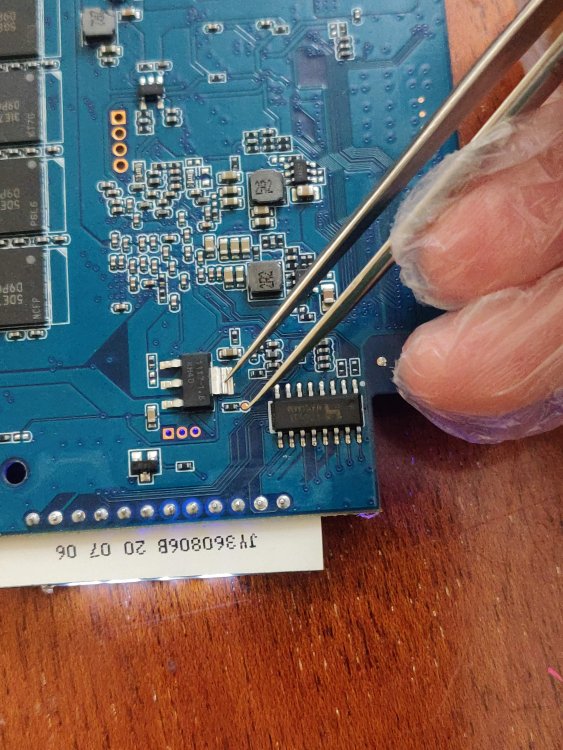
Just in case, a photo test point for RK3318 v.1.4 to launch a TV box in the maskrom mode
Edited July 16, 2023 by Energokom
@Energokom can you tell me the opp- , opp-hz as well as the opp-microvolt for 1.4 and 1.5 GHZ as i would like to test an idea i was thinking over repeatedly...
the ddrbin works at 800 for mecan we set the gpu to be at 750 mhz or higher?
and can we make the latency values a bit better and how do you know what to set it to?
i tested 1.3
i'm not worried about bricking as i can usually get these tv boxes pretty cheap online.
thanks for the testing
-
is there a way to format a 256 MB (Not GB) for booting from USB 2.0 port?
the USB is a 32 GB Flash Drive for a type a 3.0 port.
how do i make my 256MB Micro SD card for booting in this manner?
the current images are bigger than 256 Mega Bytes which is annoying me due to lack of documentation
thanks for taking the time to read this.
-
i'm on Edge Kernel 6.7.4 XFCE Ubuntu Noble 25.5.x ARM64 (RockChip64) (Armbian Beta Channel)
and so far, at 800 MHz DDRbin on an sd card with 1296 MHz CPU OC and it is rock solid stable.All I need is to have the led display with FD6551(A) and cvbs out working in newer builds
and where do i add an optical port on my board since other rk3318/3328 have the port but mine doesn't
@jockis having earlykprintf in my boot config correct?
what else should i test on my box? -
i'm running "Linux rk3318-box 6.7.4-edge-rockchip64 #1 SMP PREEMPT Mon Feb 5 20:17:12 UTC 2024 aarch64 aarch64 aarch64 GNU/Linux" (Ubuntu Noble ARM64)
(That was from "uname -a [as root]")
mine is at 800 MHz and no brick so far.
i'm using microsd card (256GB) (Legit) and it runs pretty nice except for the non flathub version of kodi (it hangs with no errors)
XFCE 4 desktop is normal fwiw and i'm experimenting with other desktop environments and window managers and compositing but hardware video acceleration does not work (Software Render only?)
P.S. (I'm Not Crying, You're Crying.)
#RK3318 #RockChip #Armbian #beta -
then what is 1596000000 ?
that is what it returned for me as root #
"cat /sys/kernel/debug/clk/dpll/clk_rate"
should i try 1333? or 1600?
i'm gonna try 1066 first.
unless i'm missing something , some of these boxes can sort of handle the higher ddrbin, we might have to play a bit with it.these boxes are a dime a dozen from most online stores....
-
i clocked it to 800 MHz and it is still working...
here is the dmesg from the 800 MHz ddrbin tweak
-
28 minutes ago, jock said:
The script allows you to go up to 800mhz, but I would not go further than 660MHz for a number of reasons
what exactly could happen if ddrbin is at 800MHz?
i have mine at 666MHz instead of 660MHz
and so far, at 666 it seems fairly stable.
-
i set my ddrbin to 666 and it works fine so far...
thanks @jock
can i push it higher?
-
@Jock
Here Are Some DTB Dumps From 2022 to 2023 (Android 9/10/11/12)
The File Names Are "CRC32".dtb -
is it possible to boot android from usb?
when i flashed the image with sdboot tool 1.69 it boots up partially and fails in short of no eMMC...
if i flash android to my 16gb usb thumbdrive and leave the micro sd card inserted so it can boot from usb....
android 9 is the first one i wanna try
-
how do i get this to boot off a usb external hdd or thumbdrive ? do i just flash it to the usb hdd and plug it into the usb 2.0 port ? or the usb 3.0 Port?
my emmc is cooked due to an error i made with the emmc clock ground button mod i did (i learned from that mistake and will improve the basic part of it.)but now the thing won't boot without a bootable sd card either in multitool
(no eMMC = No Good...)
but in armbian raw flashed to sd card, it boots up and begins the initial setup like username/etc...
i tried before 5.15.2 to boot exclusively from a usb hdd and i had no luck even when the eMMC is empty or inaccessible
(yet again boiling down to clock/gnd pcb track damage
the pad separated from the pcb due to too much heat caused from a crappy soldering iron and a loose wire pulled the track and dot and now the eMMC is kaput unless there is a way to get it working again...Grrr...!)
i've tried to get it to boot from the 2.0 port and nothing...
i tried the 3.0 port and still nothing with the card or the hdd...
i'm at a loss here.
-
it appears that someone has made a method to install libreelec for 3318/3328 on an sd card simply write the img file from libreelec to a usb sd card reader then fire up vmware with ubuntu and mount the usb sd in vmware and have the trust.img on the vm and send the command as root
dd if=trust.img of=/dev/sdb seek=24576
unmount ant shut down the vm, then edit /extlinux/extlinux.conf to point to rk3318-box.dtb
then put the rk3318-box.dtb wherever you pointed the /extlinux/extlinux.conf file to.
eject the usb sd adapter from windows.
insert the sd card into the box and boot it up, it will resize the sd card to any remaining free space for libreelec
use version 10.0.1 rk3328-arm a1 box and it mostly works except bt/wifi/led/ir, but everything else more or less works normally
-
so it appears that the rk3318/rk3328 are more or less the same so it is a possibility to get lakka / libreelec to work
use the os image with the trust file and correct dtb file and it should work pretty normal, but there needs to be more digging into the rk3318 trm and datasheet
does anyone anywhere have the technical reference manual in its entirety?
all i can find is the datasheet....
-
22 minutes ago, RetroFan90 said:
can the verbosity level go higher than 10?
if so then set it to the highest available.
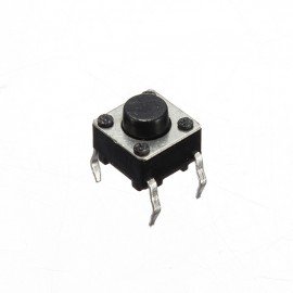
and now getting into MaskROM is easier if you solder on a push button to the emmc clock then anywhere on ground and use 2 wifi antennas pcba and solder the button to it and make sure that the button when pressed , makes connection and goes into MaskROM mode and all you need is 2 wires on the button and 1 wire on emmc clock and the other one on on ground and tape the button pcb with capton / polyamide adhesive tape so you don't short out the cpu otherwise it will halt and restart


-
can the verbosity level go higher than 10?
if so then set it to the highest available.
and now getting into MaskROM is easier if you solder on a push button to the emmc clock then anywhere on ground and use 2 wifi antennas pcba and solder the button to it and make sure that the button when pressed , makes connection and goes into MaskROM mode and all you need is 2 wires on the button and 1 wire on emmc clock and the other one on on ground and tape the button pcb with capton / polyamide adhesive tape so you don't short out the cpu otherwise it will halt and restart

CSC Armbian for RK3318/RK3328 TV box boards
in Rockchip CPU Boxes
Posted
what gpu is in the rk3318, bing seems to think there are 2 variants one with the mali450-mp2 and one with the mali450-mp5?
can you help me use the mali 450-mp2 utgard driver i know not to use ump but how do i install that instead of the lima driver.
the source is from the arm developer site.
DX940-SW-99002-r13p0-01eac0.tar