


AnonymousPi
-
Posts
35 -
Joined
-
Last visited
Content Type
Forums
Store
Crowdfunding
Applications
Events
Raffles
Community Map
Posts posted by AnonymousPi
-
-
The Banana Pi M3 has a totally different SoC / CPU and GPIO register layout to the Raspberry Pi's. You can't use that library with the Banana Pi M3, the RPI library is coded specifically for the SoCs on the RPi's.
-
Refer to this C library: https://github.com/luoyi/h3-gpio which seems quite fast, and read this comment.
It appears 10Mhz should be doable, but only if you do not read the value of the GPIO. So cache the latest value of the GPIOs locally in your code as a local variable if say, you need to do bit manipulation.
-
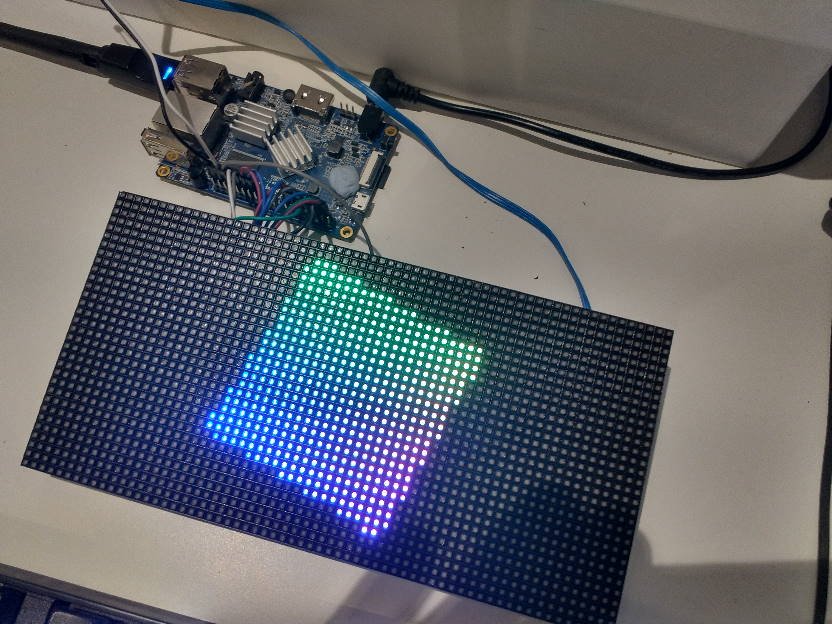
A very hackish port exists of this Raspberry PI RGB LED Matrix Library which works for Allwinner H3 devices. This works by bit-banging 14 GPIO pins simultaneously to achieve about a 10Mhz throughput / 100fps refresh rate.
Refer to here: https://github.com/mrfaptastic/opi-allwinner-h3-rgb-led-matrix
I managed to easily get up and running using an Orange PI. Refer to the README of the github repository.
-
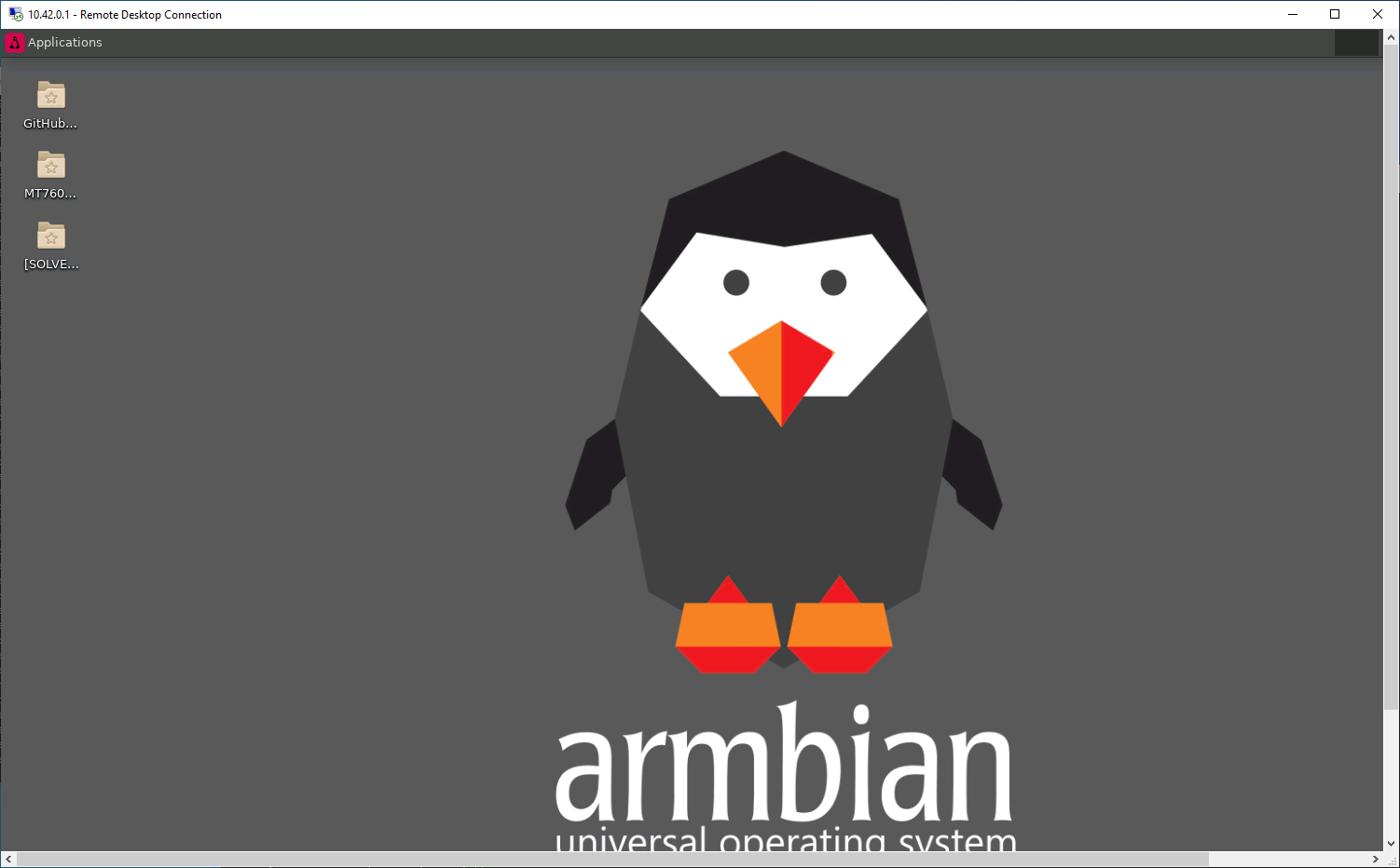
Update, for whatever reason this is broken in Armbian focal, and the issue appears to be due to an Armbian shell script that xrdp doesn't like, so after doing the install, you also need to then do:
sudo mv /etc/profile.d/armbian-check-first-login.sh /etc/profile.d/armbian-check-first-login.oldAnd volia, you'll actually get a desktop when you RDP from windows.
-
Hi Jernej, are you able to elaborate on the h265 compile flags that should be set?
-
Hi,
There have been a couple of posts about this over time, but I was wondeing if somebody could please provide concrete example / sample code that uses DMA to TX out the GPIO pin(s)?
I want to be able to TX outwards only from my Allwinner H3 device (Orange PI PC) to 16 pins in parallel (so 16 bit DMA in parallel) from a chunk of memory in RAM.Happy with a basic example if somebody has which just blasts out one GPIO pin even.
-
Hi,
There's been a few guides around on how to get RDP working with Armbian so you can login from your Windows or other PC. Some solutions mentioned in various threads here were:
- Install tightvncserver instead + x2go bloat (i.e. use VNC)
- Only login as root - didn't seem to make any difference for me
- Change some permissions of a log file in your home directory.
Well, this is what I did on my Orange PI PC running Buster desktop with Kernel 5.4, as of April 2020.
sudo apt install xrdp xorgxrdp
sudo systemctl enable xrdp
sudo reboot
... and that was it. The missing piece of the puzzel appeared to be the install of xorgxrdp, this isn't installed automatically by 'xrdp' package, and it's useless without it.

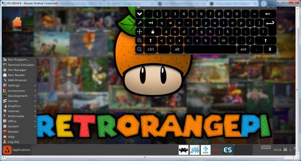
Update June 2020: Also works with RetroOrangePi 4.3 super quickly (given this is based on Armbian Bionic 18.04). Can RDP in and use Armbian Desktop whilst Kodi plays a 4k movie on the TV from the same device... Awesome!
-
12 hours ago, Igor said:
Nothing is developed in secrecy. You see what I see - we don't cover explaining where development is - it just adds to the bill we have to pay in 99%. There is a lot of work to move thing forward from the state where it got stuck. Armbian have zero R&D budget and no employees. Its amazing to get this far without ... and its not enough?OK. I'll refer to the Git going forward. My question was more out of curiosity, not a demand. Armbian on an Orange Pi PC does everything one could want now thanks to the work sunxi have done and your tireless unpaid hard work. It's amazing how far things have come.
Merry Christmas!
-
Hi Igor. Is there any update on mali integration in the mainline kernel? It does not look like there has been any movement on that pull request, so I assume hardware accelerated 3D graphics is still out of the question?
-
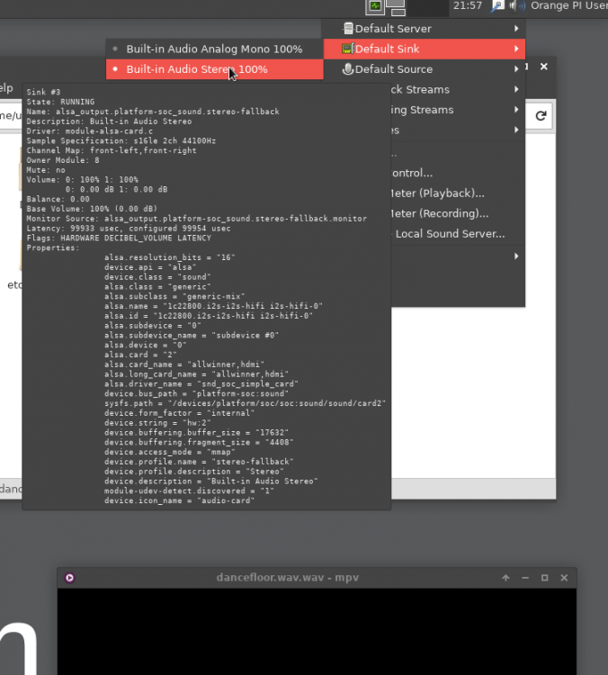
Hi,
I installed Armbian Buster Desktop last night (finally upgraded from the legacy 3.X Jessie distribution) for my Orange PI PC and HDMI Audio worked fine. Just needed to select this option in the Audio Config. Pity about the fact there's no hardware accelerated video etc... but hopefully by 2021 we might have that working in the Linux kernal!
-
Yep. The Orange Pi's are total garbage. All they really are is a Chinese TV box without a case! Might as well buy a TV box!
-
Requirements:
- Doesn't require endless stuffing around to get working with various Kernel patches.
- Not a headless device. Want to be able to plug this into HDMI to view a basic desktop.
- Linux Kernel o f > 4.6 support + future compatability. (i.e. my orange pi is basically stuck forever at 3.0 unless I want a headless box)
- SSH / Web Server
- NAS of USB attached devices
- Desktop Web Browsing with decent video playing performance
- Video playing of H265 and 264 output. Audio playing support of course (2 channel sterio is OK)
- Bonus points: Hardware H264 encoding... but not sure I'd ever actually use this.
-
https://www.raspberrypi.org/blog/raspberry-pi-4-on-sale-now-from-35/
I'd be interested to know if it still uses the same binary blob VPU to boot from.
Interested in your thoughts, especially tkaiser :-)
-
Hi,
Long time OrangePi PC user here who was going to get another of these devices but is intrigued by the TV Boxes which some can be get for about $15.
I'm confused about what is the 'best' Tv Box chip-set to get here, Amlogic (yeah I noticed the threads about them lying about CPU speed, but I don't care) or Rockchip etc.
What has the best, or is likely in the future to have good Linux Kernel support for WiFi, Ethernet, SD Card, Audio, HDMI and Hardware Decoding (and bonus points for encoding!)? Amlogic seems to be a winner right?
Any links to Aliexpress products that fit the bill?
-
Hello!
I bought an Orange Pi PC about two years ago which is still working perfectly to this day (very happy with it), but I am curious to know what would be considered the 'best' Single Board Computer at this time point time, which would be around the same price range ($15 USD).
'Best' being defined as having a decent processor, and good software support - which the Orange Pi PC eventually did.
I'm tempted to just buy another one of these for another project, but interested to know. Again, the main factor is price - $15 USD or less would be ideal.
-
On 1/6/2018 at 3:20 AM, botfap said:
There seems to be enough engineering resource to support about 10 major boards with minor variations.
I guess it's up to Igor to decide this. I think even 10 boards is too many. Perhaps the Top 5 get priority. I suspect this would mean most of the Orange PI derivatives would be the focus - but one only needs to look at the forums to see they already are.
-
On 19/09/2017 at 7:37 AM, Igor said:
We would appreciate help fixing this upstream. It has been some time since I was playing with LIRC ... And there are some other changes in Debian Stretch which are completely broken in some other way. Haven't check how it is done there yet.
Hi Igor. More than happy to help out, but I am confused as to the purpose of that sun8i.conf config file. What really needs to change is the contents within the distribution '/etc/lirc/hardware.conf' so similar to how lircd.conf is contained here.
Any insight in to how to do this appreciated. I am happy to test for stretch.
-
Updated for Ubuntu Xenial issues I faced.
-
13 hours ago, gungsukma said:
But if I power the LCD and I2C module with 3.3V, it shouldn't output 5V, right?
If run the LCD screen + IC2 module off the 3.3volt rail directly, you won't need a level converter. When I tried using the 3.3volts to power the LCD the screen was really dim/dull. I didn't check to see if it worked though. If it did, then you've saved yourself a bit of hassle :-)
-
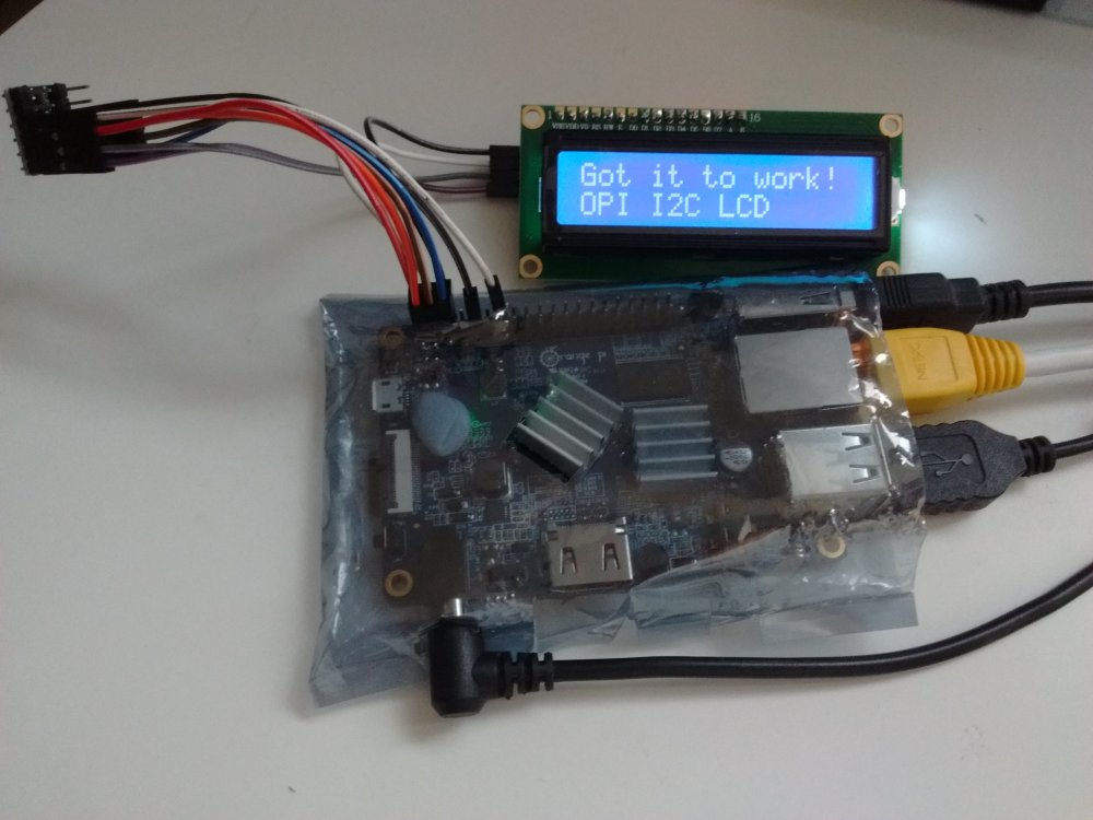
Hi All,
I recently bought a cheap 16 character, 2 row LCD display from aliexpress.com for use with my Orange Pi PC. I got it to work without too much pain, but I thought I would document it here for the benefit of others. Some good instructions are already available on the internet, but there are some tweaks required for the Orange PI.
Armbian I believe already has the I2C module compiled into the kernel directly. So no Linux Kernal insmod work required, unlike what many Raspberry PI guides seem to imply.
Step 1) Buy the things you will need.
1. You obviously need a 1602 LCD module which also comes with the the I2C converter. You can buy a 1602 LCD and wire it directly to the 16 GPIO pins required if you want, but that isn't the point of this guide.
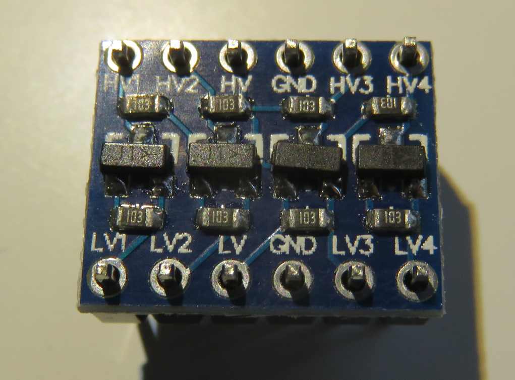
2. You will need a level shifter. The LCD display works on +5volts. The OrangePI/H3 GPIO pins are 3.3 volts. I have seen guides stating that you don't need a level shifter, but I'm sure you're slowly frying some transistors in your OrangePI over time.
3. You will need a bunch of jumper cables etc. Like these, female to female only required really.
Step 2) Wire things up accordingly.
Thanks to this fantastic guide, the instructions on wiring the Orange PI to the Level Shifter LV ('low voltage') pins, and then the Level Shifter HV ('high voltage') pins to the 1602 I2C module is pretty clear: http://www.raspberrypi-spy.co.uk/2015/05/using-an-i2c-enabled-lcd-screen-with-the-raspberry-pi/
Level Shifter OrangePI 1602 I2C Backpack LV 3.3V (pin 1) – LV1 SDA (pin 3) – LV2 SCL (pin 5) – GND GND (pin 6) GND HV 5V (pin 2) VCC HV1 SDA HV2 SCL Note, you connect the 1602 I2C module/backpack directly to the 5Volt Pin on the PI (Pin 2 or 4) and Ground (Pin 6) respectively.
Note: For some strange reason the level shifter works if you don't connect the ground pins to either side of it (i.e. Use the LV, LV1, LV2, HV, HV1 and HV2 pins only). No idea why - electrical engineering degree required I think.
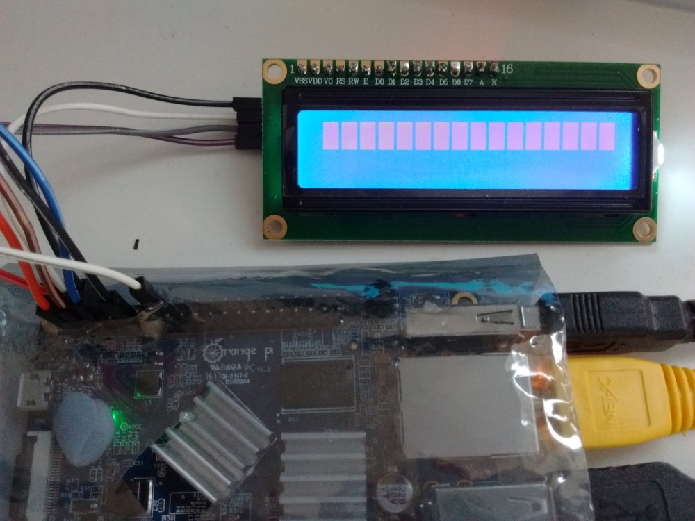
If all works well, you should see the LCD module light-up with the top row being a bunch of white bars (you might need to check the contrast setting of the module as well). White bars = uninitialised LCD screen.
Step 3) Install the required packages int Armbian
Reference: https://www.abelectronics.co.uk/kb/article/1061/i2c--smbus-and-armbian-linux
sudo apt-get install -y python-smbus i2c-tools
Step 4) Check to see what the address of the LCD Screen is:
Reference: http://www.raspberrypi-spy.co.uk/2014/11/enabling-the-i2c-interface-on-the-raspberry-pi/
user@orangepipc:~/Downloads/i2c$  sudo i2cdetect -y 0
[sudo] password for userpi:
     0  1  2  3  4  5  6  7  8  9  a  b  c  d  e  f
00:          -- -- -- -- -- -- -- -- -- -- -- -- --
10: -- -- -- -- -- -- -- -- -- -- -- -- -- -- -- --
20: -- -- -- -- -- -- -- -- -- -- -- -- -- -- -- --
30: -- -- -- -- -- -- -- -- -- -- -- -- -- -- -- 3f
40: -- -- -- -- -- -- -- -- UU -- -- -- -- -- -- --
50: -- -- -- -- -- -- -- -- -- -- -- -- -- -- -- --
60: -- -- -- -- -- -- -- -- -- -- -- -- -- -- -- --
70: -- -- -- -- -- -- -- --

user@orangepipc:~/Downloads/i2c$  sudo i2cdetect -y 1
     0  1  2  3  4  5  6  7  8  9  a  b  c  d  e  f
00:          -- -- -- -- -- -- -- -- -- -- -- -- --
10: -- -- -- -- -- -- -- -- -- -- -- -- -- -- -- --
20: -- -- -- -- -- -- -- -- -- -- -- -- -- -- -- --
30: -- -- -- -- -- -- -- -- -- -- -- -- -- -- -- --
40: -- -- -- -- -- -- -- -- -- -- -- -- -- -- -- --
50: -- -- -- -- -- -- -- -- -- -- -- -- -- -- -- --
60: -- -- -- -- -- -- -- -- -- -- -- -- -- -- -- --
70: -- -- -- -- -- -- -- --
Looks like it's 0x3f as the address on I2C bus 0 (which is apparently right according to the aliexpress buyer feedback comments)
Step 5) Download Example Script
Reference: http://www.raspberrypi-spy.co.uk/2015/05/using-an-i2c-enabled-lcd-screen-with-the-raspberry-pi/
The example script will allow you to send text to the screen via I2C. It is very similar to my scripts for the normal 16×2 screen. To download the script directly to your Pi you can use :
wget https://bitbucket.org/MattHawkinsUK/rpispy-misc/raw/master/python/lcd_i2c.py
Step 6) Adjust the Sample Script
I need to adjust the script to reference a 1602 LCD device with address 0x3f, on Orange Pi PC I2C Bus, 0. The script as it is references a device of 0x27 on Bus 1 - it won't work. You might have a LCD device of address 0x27 (you'll know from the previous step), but it seems many of the cheap LCD modules from aliexpress are 0x3f for some reason.
Adjusted script below:
#!/usr/bin/python
#--------------------------------------
#    ___  ___  _ ____
#   / _ \/ _ \(_) __/__  __ __
#  / , _/ ___/ /\ \/ _ \/ // /
# /_/|_/_/  /_/___/ .__/\_, /
#                /_/   /___/
#
#  lcd_i2c.py
#  LCD test script using I2C backpack.
#  Supports 16x2 and 20x4 screens.
#
# Author : Matt Hawkins
# Date   : 20/09/2015
#
# http://www.raspberrypi-spy.co.uk/
#
# Copyright 2015 Matt Hawkins
#
# This program is free software: you can redistribute it and/or modify
# it under the terms of the GNU General Public License as published by
# the Free Software Foundation, either version 3 of the License, or
# (at your option) any later version.
#
# This program is distributed in the hope that it will be useful,
# but WITHOUT ANY WARRANTY; without even the implied warranty of
# MERCHANTABILITY or FITNESS FOR A PARTICULAR PURPOSE.  See the
# GNU General Public License for more details.
#
# You should have received a copy of the GNU General Public License
# along with this program.  If not, see <http://www.gnu.org/licenses/>.
#
#--------------------------------------
import smbus
import time

# Define some device parameters
I2C_ADDR  = 0x3f # I2C device address
LCD_WIDTH = 16   # Maximum characters per line

# Define some device constants
LCD_CHR = 1 # Mode - Sending data
LCD_CMD = 0 # Mode - Sending command

LCD_LINE_1 = 0x80 # LCD RAM address for the 1st line
LCD_LINE_2 = 0xC0 # LCD RAM address for the 2nd line
LCD_LINE_3 = 0x94 # LCD RAM address for the 3rd line
LCD_LINE_4 = 0xD4 # LCD RAM address for the 4th line

LCD_BACKLIGHT  = 0x08  # On
#LCD_BACKLIGHT = 0x00  # Off

ENABLE = 0b00000100 # Enable bit

# Timing constants
E_PULSE = 0.0005
E_DELAY = 0.0005

#Open I2C interface
bus = smbus.SMBus(0)  # Rev 1 Pi uses 0 (and Orange PI PC, for pins 3 and 5)
#bus = smbus.SMBus(1) # Rev 2 Pi uses 1

def lcd_init():
  # Initialise display
  lcd_byte(0x33,LCD_CMD) # 110011 Initialise
  lcd_byte(0x32,LCD_CMD) # 110010 Initialise
  lcd_byte(0x06,LCD_CMD) # 000110 Cursor move direction
  lcd_byte(0x0C,LCD_CMD) # 001100 Display On,Cursor Off, Blink Off
  lcd_byte(0x28,LCD_CMD) # 101000 Data length, number of lines, font size
  lcd_byte(0x01,LCD_CMD) # 000001 Clear display
  time.sleep(E_DELAY)

def lcd_byte(bits, mode):
  # Send byte to data pins
  # bits = the data
  # mode = 1 for data
  #        0 for command

  bits_high = mode | (bits & 0xF0) | LCD_BACKLIGHT
  bits_low = mode | ((bits<<4) & 0xF0) | LCD_BACKLIGHT

  # High bits
  bus.write_byte(I2C_ADDR, bits_high)
  lcd_toggle_enable(bits_high)

  # Low bits
  bus.write_byte(I2C_ADDR, bits_low)
  lcd_toggle_enable(bits_low)

def lcd_toggle_enable(bits):
  # Toggle enable
  time.sleep(E_DELAY)
  bus.write_byte(I2C_ADDR, (bits | ENABLE))
  time.sleep(E_PULSE)
  bus.write_byte(I2C_ADDR,(bits & ~ENABLE))
  time.sleep(E_DELAY)

def lcd_string(message,line):
  # Send string to display

  message = message.ljust(LCD_WIDTH," ")

  lcd_byte(line, LCD_CMD)

  for i in range(LCD_WIDTH):
    lcd_byte(ord(message[i]),LCD_CHR)

def main():
  # Main program block

  # Initialise display
  lcd_init()

  while True:

    # Send some test
    lcd_string("RPiSpy         <",LCD_LINE_1)
    lcd_string("I2C LCD        <",LCD_LINE_2)

    time.sleep(3)

    # Send some more text
    lcd_string(">         RPiSpy",LCD_LINE_1)
    lcd_string(">        I2C LCD",LCD_LINE_2)

    time.sleep(3)

if __name__ == '__main__':

  try:
    main()
  except KeyboardInterrupt:
    pass
  finally:
    lcd_byte(0x01, LCD_CMD)
Step 7) ADD YOUR USER ACCOUNT TO 'i2c' GROUP
This is a really useful thing to do, otherwise you'll need to run the python script as ROOT (via. sudo etc.) every time. No good if you want to write a python script that runs using your normal user account and sends messages over I2C to the LCD.
Reference: https://www.abelectronics.co.uk/kb/article/1061/i2c--smbus-and-armbian-linux
sudo adduser <YOUR_USER_ID> i2c

eg: sudo adduser johnsmith i2c
Step 8) Run your script!
python lcd_i2c.py
Amazing!
Please note: You can probably use a more advanced library to output data to the LCD, but for now, it probably isn't required:
https://gist.github.com/DenisFromHR (you will need to adjust the code in 'RPi_I2C_driver.py' to refer to port=0, not port=1 to get this to work. Also change the address of the LCD device if required)
http://www.circuitbasics.com/raspberry-pi-i2c-lcd-set-up-and-programming/
What a level shifter looks like:

-
Someone on OrangePi facebook group said that he will try to port my code from OpenELEC which puts video layer in the background and normal layer in foreground. I guess that he didn't try that yet. Are you willing to do that?
I don't know enough about the XOrg to /dev/disp chain, but I'm willing to put my c coding skills to test!
However, is there any hardware limitation which would make this not possible? My only query is trying to pump the resulting VPU generated bitmap to the X framebuffer (correct me if I have no idea what I'm talking about) would probably have an adverse performance hit.
-
Hi All,
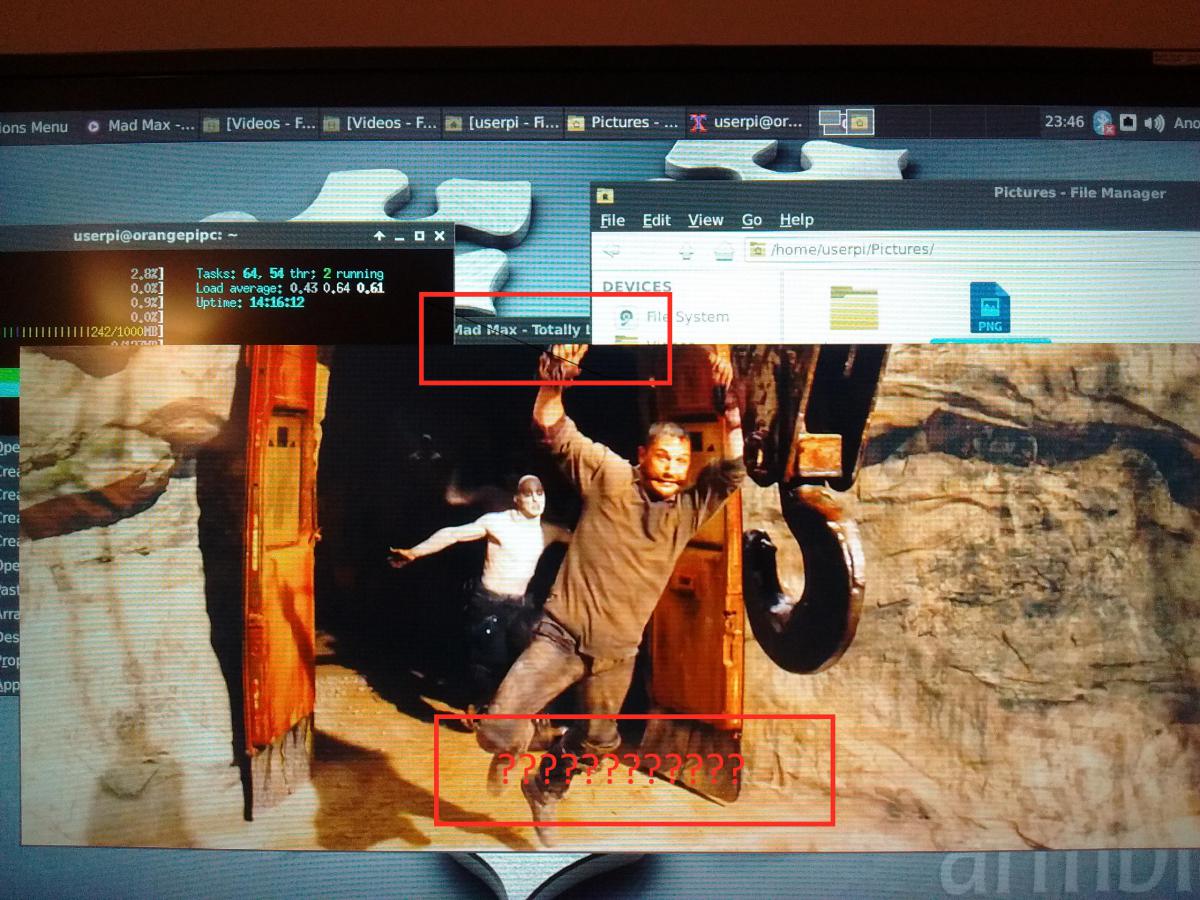
Does anybody have a solution to the issue with playing video in Armbian that the MPV on-screen controls (i.e. Pause, Stop and the Timeline) isn't visible in the bottom middle of the video frame? Is there any way to get this back?
Does it require a re-compile of mpv, or is this behaviour a result of the All winner undocumented blob based hardware acceleration, dumping pixels straight onto the frame buffer, with little one can do about it. Has anybody compiled mpv from scratch and not had this issue?
I notice that when playing video, the video paints over the top of everything - including the mouse pointer.
Photo attached with red boxes to highlight what I mean.

-
Well. Looks like I have wasted your time tkaiser. Sorry!
It seems my ISP provided an Over the Air update of my Router/Modem exactly the same time I upgraded to a 32GB Class 10 SD card. This OTA update looks to have fixed the Ethernet issue with the Orange PI PC. I can't seem the replicate the problem anymore, even with the old SD Card or older version of Armbian. If only I had another switch from the get go, I could have confirmed it was actually an issue with my networking hardware not the PI PC!
-
The Class 4 SD Card is fine from a storage perspective, but maybe it's the reduced bus speed that was killing other peripherals on the H3.
Warning: Only 7439 of 7440 MByte tested.
Test finished without errors.
You can now delete the test files *.h2w or verify them again.
Writing speed: 7.07 MByte/s
Reading speed: 20.3 MByte/s
H2testw v1.4
http://www.pcper.com/reviews/Editorial/SD-Card-Speed-Classes-Grades-Modes-and-File-Systems-Explained


x86 old games on H3 armv7 chip questions
in Beginners
Posted
Google 'retrorangepi' and simply install that, it comes with a x86 dos emulator.