Seb042
-
Posts
7 -
Joined
-
Last visited
-
@royk Finally working for the spi bus. As I didn't know what I may did wrong, I reinstalled the system, read better the doc as you suggested (the first example they show it's not the standard configuration, confusing for me at first), and finally I chose the right overlay. My armbianEnv.txt is like this to make it works: verbosity=1 bootlogo=true overlay_prefix=rockchip-rk3588 fdtfile=rockchip/rk3588-orangepi-5-plus.dtb rootdev=UUID=2cc7a9a6-afc7-4cd4-b377-6f83f2e1bf50 rootfstype=ext4 overlays=rk3588-spi0-m2-cs0-cs1-spidev usbstoragequirks=0x2537:0x1066:u,0x2537:0x1068:u I'm using the cs0-cs1 because I will need both later as I will use rotary encoders. I assume it will be the same for i2c bus, I will have to choose the right overlay. I still don't know which one would be for the i2s, but I should find that somewhere in the documentation I hope. Thanks for the answers and the tip for how to load user overlays.
-
@royk I tried with the ubuntu version from there: https://github.com/Joshua-Riek/ubuntu-rockchip I still can't manage to make the spidev bus work but at least the gpio binary show me the map of pins. But I'm confused because there are not the same names that the ones on the documentation. # gpio readall +------+-----+----------+--------+---+ PI5 PLUS +---+--------+----------+-----+------+ | GPIO | wPi | Name | Mode | V | Physical | V | Mode | Name | wPi | GPIO | +------+-----+----------+--------+---+----++----+---+--------+----------+-----+------+ | | | 3.3V | | | 1 || 2 | | | 5V | | | | 16 | 0 | SDA.2 | IN | 0 | 3 || 4 | | | 5V | | | | 15 | 1 | SCL.2 | IN | 0 | 5 || 6 | | | GND | | | | 62 | 2 | PWM14 | IN | 1 | 7 || 8 | 0 | IN | GPIO1_A1 | 3 | 33 | | | | GND | | | 9 || 10 | 0 | IN | GPIO1_A0 | 4 | 32 | | 36 | 5 | GPIO1_A4 | IN | 0 | 11 || 12 | 1 | IN | GPIO3_A1 | 6 | 97 | | 39 | 7 | GPIO1_A7 | IN | 1 | 13 || 14 | | | GND | | | | 40 | 8 | GPIO1_B0 | IN | 1 | 15 || 16 | 1 | IN | GPIO3_B5 | 9 | 109 | | | | 3.3V | | | 17 || 18 | 0 | IN | GPIO3_B6 | 10 | 110 | | 42 | 11 | SPI0_TXD | IN | 0 | 19 || 20 | | | GND | | | | 41 | 12 | SPI0_RXD | IN | 0 | 21 || 22 | 0 | IN | GPIO1_A2 | 13 | 34 | | 43 | 14 | SPI0_CLK | IN | 0 | 23 || 24 | 1 | IN | SPI0_CS0 | 15 | 44 | | | | GND | | | 25 || 26 | 1 | IN | SPI0_CS1 | 16 | 45 | | 47 | 17 | GPIO1_B7 | IN | 1 | 27 || 28 | 1 | IN | GPIO1_B6 | 18 | 46 | | 63 | 19 | GPIO1_D7 | IN | 1 | 29 || 30 | | | GND | | | | 96 | 20 | GPIO3_A0 | IN | 1 | 31 || 32 | 0 | IN | GPIO1_A3 | 21 | 35 | | 114 | 22 | GPIO3_C2 | IN | 0 | 33 || 34 | | | GND | | | | 98 | 23 | GPIO3_A2 | IN | 1 | 35 || 36 | 0 | IN | GPIO3_A5 | 24 | 101 | | 113 | 25 | GPIO3_C1 | IN | 0 | 37 || 38 | 0 | IN | GPIO3_A4 | 26 | 100 | | | | GND | | | 39 || 40 | 1 | IN | GPIO3_A3 | 27 | 99 | +------+-----+----------+--------+---+----++----+---+--------+----------+-----+------+ | GPIO | wPi | Name | Mode | V | Physical | V | Mode | Name | wPi | GPIO | +------+-----+----------+--------+---+ PI5 PLUS +---+--------+----------+-----+------+ so, according to the documentation, finally, I have to put this in Env file: overlay_prefix=orangepi-5-plus overlays=rk3588-spi0-m2-cs0-spidev After compiling the spidev_test command, and connecting spi0_TXD and spi0_TXD, I can see that the data is transmitted between both. root@seb-desktop:~/wiringOP/examples# ./spidev_test -vD /dev/spidev0.0 spi mode: 0x0 bits per word: 8 max speed: 500000 Hz (500 KHz) TX | FF FF FF FF FF FF 40 00 00 00 00 95 FF FF FF FF FF FF FF FF FF FF FF FF FF FF FF FF FF FF F0 0D |......@.........................| RX | FF FF FF FF FF FF 40 00 00 00 00 95 FF FF FF FF FF FF FF FF FF FF FF FF FF FF FF FF FF FF F0 0D |......@.........................| As soon I connect the mcp3008 the 255 value is back, as if nothing was connected... if I connect the same thing to a raspberry pi it works... really don't know where is the issue with this SPI bus on that board.
-
Yes I have the file: root@orangepi5-plus:/boot/dtb/rockchip/overlay# ls -l rk3588-spi4-m0-cs1-spidev.dtbo -rwxr-xr-x 1 root root 598 Dec 1 14:04 rk3588-spi4-m0-cs1-spidev.dtbo After reboot, I have the device: root@orangepi5-plus:~# ls -l /dev/spidev4.1 crw------- 1 root root 153, 0 Dec 4 22:39 /dev/spidev4.1 So I'm using this code ` ` ` import spidev import time spi = spidev.SpiDev(4,1) spi.max_speed_hz= 120000 while True: print(spi.readbytes(1)) time.sleep(0.1) ` ` ` And the only thing I have is 255, like nothing is read from the chip. more info: errors in the dmesg: [ 5.219022] rockchip-pinctrl pinctrl: pin gpio1-17 already requested by fecb0000.spi; cannot claim for feab0000.i2c [ 5.219027] rockchip-pinctrl pinctrl: pin-49 (feab0000.i2c) status -22 [ 5.219031] rockchip-pinctrl pinctrl: could not request pin 49 (gpio1-17) from group i2c3m0-xfer on device rockchip-pinctrl [ 5.219034] rk3x-i2c feab0000.i2c: Error applying setting, reverse things back [ 5.466121] arm-scmi firmware:scmi: Failed. SCMI protocol 17 not active. [ 5.480350] rockchip-pinctrl pinctrl: pin gpio1-18 already requested by fecb0000.spi; cannot claim for 7-0011 [ 5.480358] rockchip-pinctrl pinctrl: pin-50 (7-0011) status -22 [ 5.480365] rockchip-pinctrl pinctrl: could not request pin 50 (gpio1-18) from group i2s0-mclk on device rockchip-pinctrl [ 5.480371] ES8323 7-0011: Error applying setting, reverse things back [ 5.535846] rockchip-pinctrl pinctrl: pin gpio1-17 already requested by fecb0000.spi; cannot claim for feab0000.i2c [ 5.535856] rockchip-pinctrl pinctrl: pin-49 (feab0000.i2c) status -22 [ 5.535866] rockchip-pinctrl pinctrl: could not request pin 49 (gpio1-17) from group i2c3m0-xfer on device rockchip-pinctrl [ 5.535873] rk3x-i2c feab0000.i2c: Error applying setting, reverse things back I don't know if it's important but I'm booting from the MTD device. I tried with the wiringOP librairy, I have the same result (it's reading value of 255). The gpio readall command returns an error too: wiringPiSetup: mmap (PWM) failed: Operation not permitted root@orangepi5-plus:~/wiringOP/examples# ./spidev_test -v -D /dev/spidev4.1 spi mode: 0x0 bits per word: 8 max speed: 500000 Hz (500 KHz) TX | FF FF FF FF FF FF 40 00 00 00 00 95 FF FF FF FF FF FF FF FF FF FF FF FF FF FF FF FF FF FF F0 0D |......@.........................| RX | FF FF FF FF FF FF FF FF FF FF FF FF FF FF FF FF FF FF FF FF FF FF FF FF FF FF FF FF FF FF FF FF |................................|
-
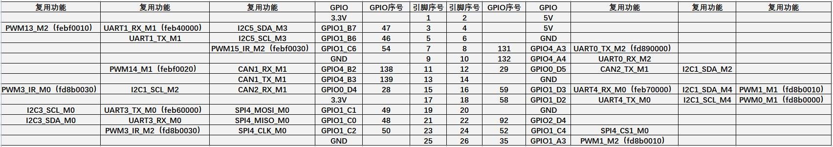
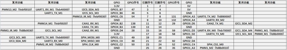
Thanks, ok so if I understand well, I should activate only the spi4_mo overlays (I attached the gpio mappings) on my case.
-
On this one, I have also activated all the ic2 overlays: https://paste.armbian.com/ivuyayuzub You can see the recurring message: 151.145487] rk3x-i2c fec80000.i2c: timeout, ipd: 0x80, state: 3 [ 151.150943] rk_hdmirx fdee0000.hdmirx-controller: hdmirx_cancel_cpu_limit_freq freq qos nod add [ 151.158929] rk_hdmirx fdee0000.hdmirx-controller: hdmirx_set_cpu_limit_freq: cpu4 policy NULL [ 151.213756] rk_hdmirx fdee0000.hdmirx-controller: hdmirx_cancel_cpu_limit_freq freq qos nod add [ 151.221833] rk_hdmirx fdee0000.hdmirx-controller: hdmirx_set_cpu_limit_freq: cpu4 policy NULL [ 151.248815] rk3x-i2c fec80000.i2c: timeout, ipd: 0x80, state: 3 [ 151.276408] rk_hdmirx fdee0000.hdmirx-controller: hdmirx_cancel_cpu_limit_freq freq qos nod add [ 151.284401] rk_hdmirx fdee0000.hdmirx-controller: hdmirx_set_cpu_limit_freq: cpu4 policy NULL If I disable the overlays finishing by m1 and m4 I don't have the messages anymore.
-
Here the logs: https://paste.armbian.com/iwufuponax I took some time to validate that my wiring is ok with a raspberry (it's ok, I can read from the mcp3008). In the config you see above, I just activated spidev buses.
-
Hi, I'm pretty new to this forum may be I will ask some already answered questions, but here they are: I just had a new orangepi 5 plus card and I failed to use the "buses": - I2s: didn't find anywhere how to activate it (i'm trying a dac as a soundcard). Didn't find the hifiberry-dac overlay neither (ok maybe this one is just for raspberry). - spi: I plugged a simple mcp3008 to the spi pins but can't read anything on it (i have the /dev/spidev0.0/1 and /dev/spiddev4.0/1 devices). I think I respected the rights pins. - i2c: when I activate the overlays in armbianEnv.txt, I can see a lot of messages every seconds with dmesg about rk-hdmi. Maybe I put too much overlays in the list ? Any help or leads would be appreciated.