jimw
Members-
Posts
16 -
Joined
-
Last visited
Recent Profile Visitors
The recent visitors block is disabled and is not being shown to other users.
-
Ryzer, Thanks a lot for your help with this. I tried a number of things and found a very simple solution that got the time down to 6 seconds. I added "gpio set 224" in the boot.cmd file and rebuilt the boot.scr file. That was it! If you happen to know any resources I could use to learn DT programming, I'm very interested in pursuing this. Thanks again, Jim
-
Thanks for your suggestion, Ryzer, I really appreciate you sharing your knowledge about this. To compile the new overlay, I first removed the "@0" from "leds: leds@0 {" line, to avoid a compiler warning, as AI suggested. The result is, after full boot, I now have /sys/class/leds/my_led/* interfaces and I can turn on the LED by "echo 1 > /sys/class/leds/my_led/brightness", as expected. But alas, the LED doesn't come on during the bootup sequence automatically by default. I am suspicious that perhaps some other hardware initialization is either overriding or overwriting the default-on statement in the dts file. Does it sound productive to decompile the sun7i-a20-bananapi-m1-plus.dtb file and look for references to PH0 to see if anybody else is trying to control it? The fact that the "echo 1 >" and "echo 0 >" commands turn the LED on and off appropriately, suggest to me the active-high nature of the pin must be set correctly. Would it help to apply a pull-up configuration as a default? If so, where would this go. BTW, if you could point me to a book or something I could use to learn DT programming, I'd appreciate it. Thanks again, Jim Oh, and this is interesting: AI suggested the kernel might be resetting the GPIO state during boot. It recommended creating a file named /etc/udev/rules.d/99-led-default.rules, containing one line saying, 'ACTION=="add", SUBSYSTEM=="leds", KERNEL=="my_led", ATTR{trigger}="default-on"'. This did cause the LED to now come on automatically during the boot-sequence! It turns on 21 seconds after power is applied. That's still slower than I'd hoped, but its an improvement. Does this information give you any ideas for overlay programming that could make it faster?
-
Thanks, I'll give this a try. I have my own code that accesses the pin controller registers during run-time, so I didn't think to use an led object. 🙂
-
One of the Bananapi-m1+ GPIO pins is connected to an LED that I need to illuminate as quickly as possible after power-on. Using an older Fedora Linux release, it turns on in 3 seconds. Using a recent Armbian build, it takes 45 seconds. I've tried many ways using services with early "After=" targets, to access /sys/class/gpio/* interfaces more quickly, and this improved it by 5 seconds, but it's still too long. So I tried adding a device tree overlay to set the default value in the pin controller. I am confident the DT overlay is getting read and parsed properly, based on seeing artifacts in debugging streams, but still, no LED illumination. Anybody got any ideas on either what's up with the DT overlay contents, or other ways to accomplish this? Any hints or suggestions would be greatly appreciated. Here's the device tree overlay .dts file (also attached). I'm sure the gpio 224 associated with PH0 is correct, since the /sys/class/gpio/* interfaces do work properly to control the LED. /dts-v1/; /plugin/; / { compatible = "allwinner,sun7i-a20"; fragment@0 { target-path = "/soc/pinctrl@1c20800"; /* A20 Pin Controller */ __overlay__ { gpio224_pin: gpio224 { pins = "PH0"; /* GPIO 224 = PH0 */ function = "gpio_out"; /* Set as output */ output-high; /* Set high at boot */ }; }; }; fragment@1 { target = <&pio>; /* GPIO controller */ __overlay__ { gpio224 { gpio-hog; gpios = <&pio 224 1>; /* Actrive HIGH */ output-high; line-name = "gpio_224_ph0"; }; }; }; }; sun7i-a20-ledon.dts
-

Banana Pi M2 Ultra boot freezing trying to scan the EMMC
jimw replied to goosnarrggh's topic in Allwinner sunxi
Nice. Thank you. -
Thanks all; I'll try this.
-
I really appreciate the help you have given me. Thank you.
-
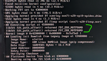
I created the .dtbo and used the following in armbianEnv.txt .. fdtfile=sun7i-a20-bananapi-m1-plus.dtb overlay_prefix=sun7i-a20 overlays=spi0-spidev No luck yet. I see an error message when executing the fixup script that is new: Any suggestions?
-
Oh, duh. I see you already did the combining and I hadn't clicked on the "reveal hidden contents" button. NVM.
-
Help me understand, "combine both overlays". Are you saying to create a new overlay called sun-7i-a20-spi0-spidev.dts? Do I literally concatenate the existing sun7i-a20-spi-spidev.dts and sun7i-a20-spi0.dts files, and change the status to "okay" for the fragment@1 from the sun7i-a20-spi-spidev.dts portion? Or are their sections from both files I should include in the new file, and are these sections needed to be in specific places in the hierarchy structure? I somewhat understand the purpose of the files, but I don't understand all the syntax and hierarchy and linkages they represent. Thanks.
-
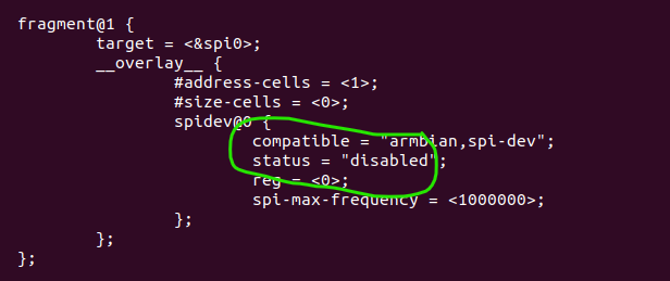
No luck yet. I got the dts source files from the build worktree folder and compiled them. I tried overlays=spi-spidev spi1 spi2 and didn't get any /dev/sp* files to access. I also tried overlays=spi-spidev spi0 since it looked to me that spi# overlay dealt with individual SPI controllers accessing different bus pins, and according to the README file in the overlay directory, only the spi0 overlay was connected to the specific pins connected to the banana pi 40-pin header. But this didn't work. I also tried: overlays=spi-spidev spi0 spi-add-cs1 but, not surprisingly, this didn't work either. I noticed while booting, all the dtbo's were found and loaded without error, and afterwards, sun7i-a20-fixup.scr was executed. This would have been the original file as I didn't copy that from the build directory. Not sure if I should have copied that as well? I see in the source sun7i-a20-spi-spidev.dts, where spi0 is disabled: Thought I might try setting this to "okay" and compiling it and copying it to the dtb/overlay folder. Any thoughts on that idea?
-
Thanks for the instruction. I'll try this right away.
-
Thanks; I appreciate your questions. The CONFIG_SPI_SPIDEV was "m" and it didn't work, so I tried recompiling with "y" and that didn't work either. "m" at least booted. I couldn't get "y" to boot (am trying this again). In armbianEnv.txt, I have: fdtfile=sun7i-a20-bananapi-m1-plus.dtb overlay_prefix=sun7i_a20 overlays=spi-spidev param_spidev_spi_bus=0 param_spidev_spi_cs=0 param_spidev_max_freq=25000000 But no /dev/spidev0.0 available after boot. As described below, I have two SPI devices attached, so I really need /dev/spidev0.0 and /dev/spidev0.1. But to test, I at least need /dev/spidev0.0 (worst case, I can manipulate CS pins myself, though I'd rather not). The SPI pins on the Banana PI Header, include CLK, MOSI, and MISO, as well as two CS pins. The two CS pins are connected to two devices on custom hardware. One is a chunk of flash memory that holds the firmware for an FPGA. Upon reset, the FPGA is filled with this contents. The other is the FPGA itself, which implements a custom protocol consisting of a 32-bit value that describes the type of the transaction followed by optional data that goes along with it. Things like reading and writing bytes or quantities of 32-bit values from designated registers or auto-incrementing registers. There is a base set of global registers and separate common registers addressed to multiple "slices" of the same logic that can be accessed individually or with simultaneous broadcast capability to all slices, which minimizes the number of SPI transactions. A typical global register transaction would be: 1. lower CS 2. send one U32 indicating something like: Writing 16 U32 values to address 0x22 3. send the 16 U32 Values 4. raise CS Using SPIDEV, this is accomplished by stacking up two SPI driver messages and sending them down using ioctl() calls. The first one sets "cs_change=0" so the CS wont change between #2 and #3 above. That's what's not working. Instead, the CS toggles and the FPGA starts a whole new protocol session when CS goes low and then high again, so it fails. P.S. 15 hours was long, but I was impressed that it actually did work!
-
Thank you sincerely. It will take me a little time to digest and try this. Right now, I have just built the kernel on the Banana Pi (15 hours to build) and am able to boot. Not quite there yet, since I lost /dev/spidev0.0. If I can get that back, then I believe I have a debugging environment and can discover the changes I will need for the steps you mentioned. Again, Thank You.
-
Glad to say creating virtual machine and getting Armbian build environment and running ./compile.sh was easy and successful for bananapim1plus / 6.1 kernel / jammy. Created SD card and booted and is running fine. Added DT overlay to enable spidev and got /dev/spidev0.0 as expected. Got new version of cross compiler to build code I formerly ran on fedora image and the SPI driver behaves differently. It pulses CS low for every transfer instead of optionally staying low for multiple transfers based on "cs_change" field in each transfer message. Found kernel source in build/cache/sources/linux-kernel-worktree/6.1__sunxi__armhf/drivers/spi, and tried editing there to begin debugging (even tried git commit there), and each time I re-run ./compile.sh, my changes are blown-away. Looking to understand what the standard workflow is for this? Do I have to use user patches? Do I have to build the kernel somewhere else and inject it into the img somewhere? Any suggestions welcome. THANK YOU.


