Jump to content

Peter Gregory

Members
  • Posts

    30
  • Joined

  • Last visited

Everything posted by Peter Gregory

  1. The answer was soldering the left/right/gnd connections directly to the SMD pads and using audio isolation transformers. They eliminated the loud pop when the audio codec kicks in and removed the ground loop causing the amp to draw too much power. The sound is great now.
  2. I finally got a configuration that works. I got a 5v 4amp wall power supply to run the Orange PI PC I connected my amp power to the 2 5v header pins and 2 and pins. I connected the audio jack's L and R & common ground using the SMD pads instead of an audio plug (My plug was stereo and was shorting the video out to audio channels) I put the audio signals through a audio isolation transformer to get rid of the ground loop current and filter out the big pop when the audio codec kicks on That's it! The 4a is strong enough to run the board and the amp without significant voltage drop on high power usage (~200ma draw from amp) The isolation transformers eliminate the ground loop hum and chatter from the board operations. The audio is clean and loud.
  3. Turns out this issue was my audio jack. I think the stereo plug was shorting the video out and audio channels together causing a hot mess. I bypassed the audio jack by soldering my analog audio connections directly to the SMD pads in the audio jack and the sound is great. Now I'm having trouble getting my PAM8403 2x 3W Mini Digital Power Amplifier Board AMP Class D and orange pi pc to work with a single power supply. I can power the pi from a 2a 5v supply and the amp from a separate 1a 5v supply and it works great. No hum or audio problems (I thought it could be louder, but it is not bad). If I attempt to power both devices from a single 3a (or more, I tried up to 5a) 5v supply it does not work. It looks like I have a big ground loop problem with the audio outputs and the power amp. I have some audio isolation transformers on order and I hope that will fix the issue. Once the analog driver kicks on, I get a loudish "pop" from the amp and the 5v voltage dips briefly below the minimum to keep the board running. Even with separate power supplies, I see a lot of ripple and drops from the 5v supply on the amp while playing at higher volumes. I'm not sure if I need to add a low/high filter to keep the low / high frequencies out or if the audio isolation will do the trick. Any advice on getting an external audio amp to work well with this board will be appreciated.
  4. Yeah, I think you are right. I got the device working on an Orange PI PC, but I wanted a lower cost board with wifi. I thought I could use the same technique to get the display working on my Orange PI Zero 2, but I couldn't find any pins I could use to drive the display. The device tree allocated all the exposed pins for other uses. Has anyone had luck getting a display like this one working on an Orange PI Zero W2 or similar hardware?
  5. I'm using image Armbian_23.8.3_Orangepizero2_bookworm_current_6.1.53 I'm building a DTS overlay for a SPI Touchscreen and every pin I try to use is showing this error: [ 1.441808] sun50i-h616-pinctrl 300b000.pinctrl: pin PC11 already requested by 5011000.spi; cannot claim for 300b000.pinctrl:75 [ 1.441817] sun50i-h616-pinctrl 300b000.pinctrl: pin-75 (300b000.pinctrl:75) status -22 [ 1.441829] sun6i-spi 5011000.spi: cannot register SPI master I'm trying to configure my touchscreen dts to use the SPI1.0 & SPI1.1. However, the pins exposed on the headers are all allocated for device use under 300b000.pinctrl. How do you allocate header pins for another use? I need 5 pins + SPI1 for the touchscreen to work. My dts /dts-v1/; /plugin/; / { compatible = "allwinner,sun8i-h3"; fragment@0 { target = <&pio>; __overlay__ { spi1_cs1: spi1_cs1 { pins = "PC11"; function = "gpio_out"; output-high; }; opiz_display_pins: opiz_display_pins { pins = "PC9", "PC6", "PC5"; function = "gpio_out"; }; ads7846_pins: ads7846_pins { pins = "PH6"; function = "irq"; }; }; }; fragment@1 { target = <&spi1>; __overlay__ { #address-cells = <1>; #size-cells = <0>; status = "okay"; pinctrl-1 = <&spi1_cs1>; pinctrl-names = "default", "default"; cs-gpios= <0>, <&pio 2 11 0>; /* PH9 PC11 */ opizdisplay: opiz-display@0 { reg = <0>; /* Chip Select 0 */ compatible = "ilitek,ili9341"; spi-max-frequency = <16000000>; status = "okay"; pinctrl-names = "default"; pinctrl-0 = <&opiz_display_pins>; rotate = <90>; bgr = <0>; fps = <10>; buswidth = <8>; dc-gpios = <&pio 2 6 0>; /* PC6 */ reset-gpios = <&pio 2 9 1 >; /* PC9 */ led-gpios=<&pio 2 5 0>; /* PC5 */ debug=<0>; }; ads7846: ads7846@1 { reg = <1>; /* Chip Select 1 */ compatible = "ti,ads7846"; spi-max-frequency = <500000>; status = "okay"; pinctrl-names = "default"; pinctrl-0 = <&ads7846_pins>; interrupt-parent = <&pio>; interrupts = <7 6 2>; /* PH6 IRQ_TYPE_EDGE_FALLING */ pendown-gpio = <&pio 7 6 0>; /* PH6 */ /* driver defaults, optional */ ti,x-min = /bits/ 16 <0>; ti,y-min = /bits/ 16 <0>; ti,x-max = /bits/ 16 <0x0FFF>; ti,y-max = /bits/ 16 <0x0FFF>; ti,pressure-min = /bits/ 16 <0>; ti,pressure-max = /bits/ 16 <0xFFFF>; ti,x-plate-ohms = /bits/ 16 <400>; }; }; }; };
  6. So, it is working! It just wasn't working with my edge custom built image: Armbian_23.08.0-trunk_Orangepipc_bookworm_edge_6.5.5_minimal.img. I reproduced my efforts on the latest armbian image Armbian_23.8.1_Orangepipc_bookworm_current_6.1.47.img and it is working as expected. The display works and the touch events are working properly. I changed my wiring to test swapping LCD and Touch. Here is my working wiring chart: 1 - VCC (1) 3.3v 2 - GND (6) GND 3 - CS (24) PC3 SPI0 CS 4 - RESET (26) PA21 GPIO 11 5 - DC (31) PA8 GPIO 22 6 - SDI (MOSI) (19) PC0 SPI0 MOSI 7 - SCLK (23) PC2 SPI0 CLK 8 - LED (33) PA9 GPIO 23 9 - SDO (MISO) (21) PC1 SPI0 MISO 10 - T_CLK (23) PC2 SPI0 CLK * 11 - T_CS (18) PC7 GPIO 5 12 - T_DIN (19) PC0 SPI0 MOSI * 13 - T_DO (21) PC1 SPI0 MISO * 14 - T_IRQ (29) PA7 GPIO 21 Here are steps to get the display working: Install latest armbian image: Armbian_23.8.1_Orangepipc_bookworm_current_6.1.47.img sudo armbian-config enable desktop sudo nano /boot/armbianEnv.txt user_overlays=touchscreen extraargs=fbcon=map:1 nano touchscreen.dts /dts-v1/; /plugin/; / { compatible = "allwinner,sun8i-h3"; fragment@0 { target = <&pio>; __overlay__ { spi0_cs1: spi0_cs1 { pins = "PC7"; function = "gpio_out"; output-high; }; opiz_display_pins: opiz_display_pins { pins = "PA21", "PA8", "PA9"; function = "gpio_out"; }; ads7846_pins: ads7846_pins { pins = "PA7"; function = "irq"; }; }; }; fragment@1 { target = <&spi0>; __overlay__ { #address-cells = <1>; #size-cells = <0>; status = "okay"; pinctrl-1 = <&spi0_cs1>; pinctrl-names = "default", "default"; cs-gpios= <0>, <&pio 2 7 0>; /* PC7 */ ads7846: ads7846@1 { reg = <0>; /* Chip Select 0 */ compatible = "ti,ads7846"; spi-max-frequency = <500000>; status = "okay"; pinctrl-names = "default"; pinctrl-0 = <&ads7846_pins>; interrupt-parent = <&pio>; interrupts = <0 7 2>; /* PA7 IRQ_TYPE_EDGE_FALLING */ pendown-gpio = <&pio 0 7 0>; /* PA7 */ /* driver defaults, optional */ ti,x-min = /bits/ 16 <0>; ti,y-min = /bits/ 16 <0>; ti,x-max = /bits/ 16 <0x0FFF>; ti,y-max = /bits/ 16 <0x0FFF>; ti,pressure-min = /bits/ 16 <0>; ti,pressure-max = /bits/ 16 <0xFFFF>; ti,x-plate-ohms = /bits/ 16 <400>; }; opizdisplay: opiz-display@0 { reg = <1>; /* Chip Select 1 */ compatible = "ilitek,ili9341"; spi-max-frequency = <16000000>; status = "okay"; pinctrl-names = "default"; pinctrl-0 = <&opiz_display_pins>; rotate = <90>; bgr = <0>; fps = <10>; buswidth = <8>; dc-gpios = <&pio 0 8 0>; /* PA8 */ reset-gpios = <&pio 0 21 1 >; /* PA21 */ led-gpios=<&pio 0 9 0>; /* PA9 */ debug=<0>; }; }; }; }; sudo armbian-add-overlay touchscreen.dts sudo nano /etc/modules-load.d/fbtft.conf fbtft fb_ili9341 sudo nano /usr/share/X11/xorg.conf.d/99-fbdev.conf Section "Device" Identifier "myfb" Driver "fbdev" Option "fbdev" "/dev/fb1" EndSection reboot and your display and touch should work!
  7. The LCD part is working well. The touch part, not so well. I try running evtest and selecting the touch device, but I don't see activity. Connecting to the scope, I see the driver query the device and get data back, but I guess it is not decoding the results properly. even with activity like listed above, it is not returning any results from evtest. sudo evtest No device specified, trying to scan all of /dev/input/event* Available devices: /dev/input/event0: gpio-keys /dev/input/event1: ADS7846 Touchscreen /dev/input/event2: sunxi-ir /dev/input/event3: BRLTTY 6.5 Linux Screen Driver Keyboard Select the device event number [0-3]: 1 Input driver version is 1.0.1 Input device ID: bus 0x1c vendor 0x0 product 0x1ea6 version 0x0 Input device name: "ADS7846 Touchscreen" Supported events: Event type 0 (EV_SYN) Event type 1 (EV_KEY) Event code 330 (BTN_TOUCH) Event type 3 (EV_ABS) Event code 0 (ABS_X) Value 0 Min 1 Max 65535 Event code 1 (ABS_Y) Value 0 Min 1 Max 65535 Event code 24 (ABS_PRESSURE) Value 0 Min 0 Max 255 Properties: Testing ... (interrupt to exit) .... Crickets.... Does anyone have experience with the ads7843 driver interfacing with a XPT2046 chip? Is there a magic configuration that makes it decode the data properly? It looks like it should be valid to me.
  8. I'm getting closer - I finally got the touch and display to initialize. The trick is determining which GPIO pins can be used and which support interrupts. Here is the pinout and connection diagram I am using: 1 - VCC (1) 3.3v 2 - GND (6) GND 3 - CS (24) PC3 SPI0 CS 4 - RESET (29) PA7 GPIO 21 5 - DC (31) PA8 GPIO 22 6 - SDI (MOSI) (19) PC0 SPI0 MOSI 7 - SCLK (23) PC2 SPI0 CLK 8 - LED (33) PA9 GPIO 23 9 - SDO (MISO) (21) PC1 SPI0 MISO 10 - T_CLK (23) PC2 SPI0 CLK * 11 - T_CS (26) PC7 GPIO 5 12 - T_DIN (19) PC0 SPI0 MOSI * 13 - T_DO (21) PC1 SPI0 MISO * 14 - T_IRQ (18) PA21 GPIO 11 (Supports interrupt) DTS that is working /dts-v1/; /plugin/; / { compatible = "allwinner,sun8i-h3"; fragment@0 { target = <&pio>; __overlay__ { spi0_cs1: spi0_cs1 { pins = "PC7"; function = "gpio_out"; output-high; }; opiz_display_pins: opiz_display_pins { pins = "PA7", "PA8", "PA9"; function = "gpio_out"; }; ads7846_pins: ads7846_pins { pins = "PA21"; function = "irq"; }; }; }; fragment@1 { target = <&spi0>; __overlay__ { #address-cells = <1>; #size-cells = <0>; status = "okay"; pinctrl-1 = <&spi0_cs1>; pinctrl-names = "default", "default"; cs-gpios= <0>, <&pio 2 7 0>; opizdisplay: opiz-display@0 { reg = <0>; /* Chip Select 0 */ compatible = "ilitek,ili9341"; spi-max-frequency = <16000000>; status = "okay"; pinctrl-names = "default"; pinctrl-0 = <&opiz_display_pins>; rotate = <90>; bgr = <0>; fps = <10>; buswidth = <8>; dc-gpios = <&pio 0 8 0>; /* PA8 */ reset-gpios = <&pio 0 7 1 >; /* PA7 */ led-gpios=<&pio 0 9 0>; /* PA9 */ debug=<4>; }; ads7846: ads7846@1 { reg = <1>; /* Chip Select 1 */ compatible = "ti,ads7846"; spi-max-frequency = <2000000>; status = "okay"; pinctrl-names = "default"; pinctrl-0 = <&ads7846_pins>; interrupt-parent = <&pio>; interrupts = <0 21 2>; /* PC7 IRQ_TYPE_EDGE_FALLING */ pendown-gpio = <&pio 0 21 0>; /* PC7 */ /* driver defaults, optional */ ti,x-min = /bits/ 16 <0>; ti,y-min = /bits/ 16 <0>; ti,x-max = /bits/ 16 <0x0FFF>; ti,y-max = /bits/ 16 <0x0FFF>; ti,pressure-min = /bits/ 16 <0>; ti,pressure-max = /bits/ 16 <0xFFFF>; ti,x-plate-ohms = /bits/ 16 <400>; }; }; }; }; Using this configuration I get the following from dmesg: [ 6.231015] fbtft: module is from the staging directory, the quality is unknown, you have been warned. [ 6.234683] fb_ili9341: module is from the staging directory, the quality is unknown, you have been warned. [ 6.235590] systemd[1]: Mounting sys-fs-fuse-connections.mount - FUSE Control File System... [ 6.235823] fb_ili9341 spi0.0: fbtft_property_value: buswidth = 8 [ 6.235857] fb_ili9341 spi0.0: fbtft_property_value: debug = 4 [ 6.235870] fb_ili9341 spi0.0: fbtft_property_value: rotate = 90 [ 6.235892] fb_ili9341 spi0.0: fbtft_property_value: fps = 10 [ 6.573436] fb_ili9341 spi0.0: Display update: 1787 kB/s, fps=0 [ 6.574355] Console: switching to colour frame buffer device 40x30 [ 6.575115] graphics fb1: fb_ili9341 frame buffer, 320x240, 150 KiB video memory, 16 KiB buffer memory, fps=10, spi0.0 at 16 MHz [ 8.471370] SPI driver ads7846 has no spi_device_id for ti,tsc2046 [ 8.471402] SPI driver ads7846 has no spi_device_id for ti,ads7843 [ 8.471410] SPI driver ads7846 has no spi_device_id for ti,ads7845 [ 8.471417] SPI driver ads7846 has no spi_device_id for ti,ads7873 [ 8.471620] ads7846 spi0.1: setup mode 0, 8 bits/w, 2000000 Hz max --> 0 [ 8.471794] ads7846 spi0.1: supply vcc not found, using dummy regulator [ 8.481255] systemd[1]: Finished systemd-binfmt.service - Set Up Additional Binary Formats. [ 8.486590] ads7846 spi0.1: touchscreen, irq 62 [ 8.501181] input: ADS7846 Touchscreen as /devices/platform/soc/1c68000.spi/spi_master/spi0/spi0.1/input/input2 I try touching the screen, but I'm not set up to use the new touch device as the main input yet. I think I'm very close to getting this display operational. running everest I get the following: everest 'No device specified, trying to scan all of /dev/input/event* Not running as root, no devices may be available. Available devices: /dev/input/event0: gpio-keys /dev/input/event1: sunxi-ir /dev/input/event2: ADS7846 Touchscreen /dev/input/event3: BRLTTY 6.5 Linux Screen Driver Keyboard evtest --grab /dev/input/event2 Input driver version is 1.0.1 Input device ID: bus 0x1c vendor 0x0 product 0x1ea6 version 0x0 Input device name: "ADS7846 Touchscreen" Supported events: Event type 0 (EV_SYN) Event type 1 (EV_KEY) Event code 330 (BTN_TOUCH) Event type 3 (EV_ABS) Event code 0 (ABS_X) Value 0 Min 0 Max 4095 Event code 1 (ABS_Y) Value 0 Min 0 Max 4095 Event code 24 (ABS_PRESSURE) Value 0 Min 0 Max 65535 Properties: Testing ... (interrupt to exit) Event: time 1695777743.332287, type 1 (EV_KEY), code 330 (BTN_TOUCH), value 1 Event: time 1695777743.332287, type 3 (EV_ABS), code 0 (ABS_X), value 562 Event: time 1695777743.332287, type 3 (EV_ABS), code 1 (ABS_Y), value 2228 Event: time 1695777743.332287, type 3 (EV_ABS), code 24 (ABS_PRESSURE), value 64919 Event: time 1695777743.332287, -------------- SYN_REPORT ------------ Event: time 1695777743.340652, type 1 (EV_KEY), code 330 (BTN_TOUCH), value 0 Event: time 1695777743.340652, type 3 (EV_ABS), code 24 (ABS_PRESSURE), value 0 Event: time 1695777743.340652, -------------- SYN_REPORT ------------ Event: time 1695777762.428725, type 1 (EV_KEY), code 330 (BTN_TOUCH), value 1 Event: time 1695777762.428725, type 3 (EV_ABS), code 0 (ABS_X), value 21 Event: time 1695777762.428725, type 3 (EV_ABS), code 1 (ABS_Y), value 3185 Event: time 1695777762.428725, type 3 (EV_ABS), code 24 (ABS_PRESSURE), value 65502 Event: time 1695777762.428725, -------------- SYN_REPORT ------------ Event: time 1695777762.440670, type 1 (EV_KEY), code 330 (BTN_TOUCH), value 0 Event: time 1695777762.440670, type 3 (EV_ABS), code 24 (ABS_PRESSURE), value 0 Event: time 1695777762.440670, -------------- SYN_REPORT ------------ I'm getting touch events. I still need to find out how to set the touch device as the default pointer. After testing and trying to get the touch working consistently I've come to the conclusion the interrupt is not working as expected. I can hook my device up to a scope and every touch will cause a drop in the pen down pin, but I don't see a corresponding drop in CS1 pin to SPI activity to get the touch data. Every now and then it will query the touch device in response to a touch event, but it does it only after repeated touch & move operations. I don't see a way to turn on debugging for the touch module, so it is difficult to determine where the problem is. Anyone else see this behavior?
  9. Finally some success! My original wiring was correct. MISO goes to MISO and MOSI goes to MOSI. The problem was in my DTS. This device has a 8 bit bus, not a 16 bit bus. I also ran into a problem that pin A21 would not follow the DTS and was active all the time - making the touch active and corrupting the SPI data. I moved it to PC4. Correct wiring: 2.8 Inch TFT SPI 240x320, ads7846 Touch 1 - VCC (1) 3.3v 2 - GND (6) GND 3 - CS (24) PC3 SPI0 CS 4 - RESET (29) PA7 GPIO 21 5 - DC (31) PA8 GPIO 22 6 - SDI (MOSI) (19) PC0 SPI0 MOSI 7 - SCLK (23) PC2 SPI0 CLK 8 - LED (33) PA9 GPIO 23 9 - SDO (MISO) (21) PC1 SPI0 MISO 10 - T_CLK (23) PC2 SPI0 CLK * 11 - T_CS (16) PC4 GPIO 4 12 - T_DIN (19) PC0 SPI0 MOSI * 13 - T_DO (21) PC1 SPI0 MISO * 14 - T_IRQ (18) PC7 GPIO.5 Correct DTS for the display (still working on the touch controller...) /dts-v1/; /plugin/; / { compatible = "allwinner,sun8i-h3"; fragment@1 { target = <&pio>; __overlay__ { spi0_cs1_pin: spi0-cs1-pin { pins = "PC4"; function = "gpio_out"; output-high; }; ili9341_rst: ili9341-rst { pins = "PA7"; function = "gpio_out"; output-high; }; ili9341_dc: ili9341-dc { pins = "PA8"; function = "gpio_out"; output-high; }; ili9341_led: ili9341-led { pins = "PA9"; function = "gpio_out"; output-high; }; ads7846_pin: ads7846-pin { pins = "PC7"; function = "gpio_in"; }; }; }; fragment@2 { target = <&pio>; __overlay__ { ads7846_pins: ads7846_pins { pins = "PC4", "PC7"; /*SPI0.1 CS, PINDOWN*/ function = "gpio_out", "gpio_in" ; }; }; }; fragment@3 { target = <&pio>; __overlay__ { ili9341_pins: ili9341_pins { pins = "PA7", "PA8", "PA9"; /*RESET, DC_RS, LED*/ function = "gpio_out", "gpio_out", "gpio_out" ; }; }; }; fragment@4 { target = <&spi0>; __overlay__ { #address-cells = <1>; #size-cells = <0>; cs_gpios = <0>, <&pio 2 4 0>; pinctrl-0 = <&spi0_pins>; status = "okay"; ili9341: ili9341@0 { compatible = "ilitek,ili9341"; reg = <0>; pinctrl-names = "default"; pinctrl-0 = <&ili9341_pins>; status = "okay"; debug = <0>; rotate = <0>; bgr = <1>; fps = <10>; buswidth = <8>; regwidth = <8>; reset-gpios = <&pio 0 7 1>; dc-gpios = <&pio 0 8 0>; led-gpios = <&pio 0 9 0>; spi-max-frequency = <16000000>; }; xpt2046: xpt2046@1 { compatible = "ti,ads7846"; reg = <1>; pinctrl-names = "default"; pinctrl-0 = <&ads7846_pin>; interrupts = <2 7 2>; interrupt-parent = <&pio>; pendown_gpio = <&pio 2 7 2>; status = "okay"; spi-max-frequency = <10000000>; ti,keep-vref-on = <1>; ti,x-min = /bits/ 16 <00>; ti,x-max = /bits/ 16 <0xFFF>; ti,y-min = /bits/ 16 <00>; ti,y-max = /bits/ 16 <0xFFF>; ti,x-plate-ohms = /bits/ 16 <60>; ti,pressure-max = /bits/ 16 <255>; ti,swap-xy = <0>; }; }; }; }; Steps to get the display up and running: sudo nano /boot/armbianEnv.txt disp_mode=720p60 user_overlays=touchscreen extraargs=fbcon=map:1 nano touchscreen.dts <insert DTS source from above> sudo armbian-add-overlay touchscreen.dts sudo nano /etc/modules-load.d/fbtft.conf fbtft fb_ili9341 sudo nano /usr/share/X11/xorg.conf.d/99-fbdev.conf Section "Device" Identifier "myfb" Driver "fbdev" Option "fbdev" "/dev/fb1" EndSection reboot and your console / desktop will show in the LCD display I'm still getting the error from the touch driver: [ 9.423938] SPI driver ads7846 has no spi_device_id for ti,tsc2046 [ 9.423975] SPI driver ads7846 has no spi_device_id for ti,ads7843 [ 9.423984] SPI driver ads7846 has no spi_device_id for ti,ads7845 [ 9.423991] SPI driver ads7846 has no spi_device_id for ti,ads7873 [ 9.424199] ads7846: probe of spi0.1 failed with error -22 I'm trying to find a DTS with a shared SPI instance (SPI0.0 and SPI0.1). I'm pretty sure my setup for the second CS is causing the issue. At least now the display works when it is fully wired up.
  10. I made a rookie mistake - I connect MOSI -> MOSI and MISO -> MISO (input to input, output to output). No wonder it would not work. I corrected my wiring connections and updated my dts: 2.8 Inch TFT SPI 240x320, ads7846 Touch => Orange PI PC 1 - VCC => (1) 3.3v 2 - GND => (6) GND 3 - CS => (24) PC3 SPI0 CS 4 - RESET => (29) PA7 GPIO 21 5 - DC => (31) PA8 GPIO 22 6 - SDI (MOSI) => (21) PC1 SPI0 MISO 7 - SCLK => (23) PC2 SPI0 CLK 8 - LED => (33) PA9 GPIO 23 9 - SDO (MISO) => (19) PC0 SPI0 MOSI 10 - T_CLK => (23) PC2 SPI0 CLK * 11 - T_CS => (26) PA21 GPIO 11 12 - T_DIN => (21) PC1 SPI0 MISO * 13 - T_DO => (19) PC0 SPI0 MOSI * 14 - T_IRQ => (18) GPIO.5 PC7 /dts-v1/; /plugin/; / { compatible = "allwinner,sun8i-h3"; fragment@1 { target = <&pio>; __overlay__ { spi0_cs1_pin: spi0-cs1-pin { pins = "PA21"; function = "gpio_out"; output-high; }; ili9341_rst: ili9341-rst { pins = "PA7"; function = "gpio_out"; output-high; }; ili9341_dc: ili9341-dc { pins = "PA8"; function = "gpio_out"; output-high; }; ili9341_led: ili9341-led { pins = "PA9"; function = "gpio_out"; output-high; }; ads7846_pin: ads7846-pin { pins = "PC7"; function = "gpio_in"; }; }; }; fragment@3 { target = <&pio>; __overlay__ { ili9341_pins: ili9341_pins { pins = "PA7", "PA8", "PA9"; /*RESET, DC_RS, LED*/ function = "gpio_out", "gpio_out", "gpio_out" ; }; }; }; fragment@4 { target = <&spi0>; __overlay__ { #address-cells = <1>; #size-cells = <0>; cs_gpios = <0>, <&spi0_cs1_pin>; pinctrl-0 = <&spi0_pins>; status = "okay"; ili9341: ili9341@0 { compatible = "ilitek,ili9341"; reg = <0>; pinctrl-names = "default"; pinctrl-0 = <&ili9341_pins>; status = "okay"; debug = <0>; rotate = <90>; bgr; fps = <10>; buswidth = <8>; regwidth = <16>; reset-gpios = <&pio 0 7 1>; dc-gpios = <&pio 0 8 0>; led-gpios = <&pio 0 9 0>; spi-max-frequency = <1000000>; }; xpt2046: xpt2046@1 { compatible = "ti,ads7846"; reg = <1>; pinctrl-names = "default"; pinctrl-0 = <&spi0_cs1_pin>; interrupts = <&ads7846_pin>; interrupt-parent = <&pio>; pendown_gpio = <&ads7846_pin>; status = "okay"; spi-max-frequency = <1000000>; ti,keep-vref-on = <1>; ti,x-min = /bits/ 16 <00>; ti,x-max = /bits/ 16 <0xFFF>; ti,y-min = /bits/ 16 <00>; ti,y-max = /bits/ 16 <0xFFF>; ti,x-plate-ohms = /bits/ 16 <60>; ti,pressure-max = /bits/ 16 <255>; ti,swap-xy = <0>; }; }; }; }; Now, my display will light up on reboot but I still get no images and no activity. I thought I could force an image on /dev/fb1 using the following command: sudo fbi -vt 1 -noverbose -d /dev/fb1 /boot/boot.bmp but the screen does not change. When I got the fbtft_device working in the legacy kernel, the screen would blank after initialization, so something must still be wrong
  11. The issue with pen down GPIO (PA10) is that the Orange PI PC dts is using it for the power pins: leds { compatible = "gpio-leds"; pwr_led { label = "orangepi:green:pwr"; gpios = <0x46 0x00 0x0a 0x00>; default-state = "on"; }; status_led { label = "orangepi:red:status"; gpios = <0x16 0x00 0x0f 0x00>; }; }; I moved the GPIO to PC7 and got past the GPIO error. I'm still getting SPI error -22. I think there is something wrong with my 2nd SPI CS declaration. Not much progress tonight.
  12. I've tried powering the hat from the header pins using the Orange PI PC board power, but that did not work well. The board would reset when the amp would play. I also tried connecting the power to the hat and powering the Orange PI PC from the header +5v pins, thinking that might help with the voltage drop, same result. It really seems like the power amp + Orange PI PC draws more power than the 5v 3a supply can supply, or it drops the voltage too much. I would think 3a could power the board & amp, but maybe not. I'll hook a scope to it and see what's happening to the power levels. Do I need isolation capacitors (0.1uf + 100k resistor to ground) on the audio output to remove positive voltage bias on the analog output? Am I driving the amp always & draining power?
  13. Getting some more progress... Updated my DTS to the following: /dts-v1/; /plugin/; / { compatible = "allwinner,sun8i-h3"; fragment@1 { target = <&pio>; __overlay__ { spi0_cs1_pin: spi0-cs1-pin { pins = "PA21"; function = "gpio_out"; }; ili9341_rst: ili9341-rst { pins = "PA7"; function = "gpio_out"; }; ili9341_dc: ili9341-dc { pins = "PA8"; function = "gpio_out"; }; ili9341_led: ili9341-led { pins = "PA9"; function = "gpio_out"; output-high; }; ads7846_pin: ads7846-pin { pins = "PA10"; function = "irq"; }; }; }; fragment@3 { target = <&pio>; __overlay__ { ili9341_pins: ili9341_pins { pins = "PA7", "PA8", "PA9"; /*RESET, DC_RS, LED*/ function = "gpio_out", "gpio_out", "gpio_out" ; }; }; }; fragment@4 { target = <&spi0>; __overlay__ { #address-cells = <1>; #size-cells = <0>; cs_gpios = <0>, <&pio 0 21 0>; pinctrl-0 = <&spi0_pins>; status = "okay"; ili9341: ili9341@0 { compatible = "ilitek,ili9341"; reg = <0>; pinctrl-names = "default"; pinctrl-0 = <&ili9341_pins>; status = "okay"; debug=<1>; rotate = <90>; bgr; fps = <25>; buswidth = <8>; regwidth = <16>; reset-gpios = <&pio 0 7 0>; dc-gpios = <&pio 0 8 0>; led-gpios = <&pio 0 9 0>; }; xpt2046: xpt2046@1 { compatible = "ti,ads7846"; reg = <1>; pinctrl-names = "default"; pinctrl-0 = <&spi0_cs1_pin>; interrupts = <0 10 2>; interrupt-parent = <&pio>; pendown_gpio = <&pio 0 10 0>; status = "okay"; spi-max-frequency = <1000000>; ti,keep-vref-on = <1>; ti,x-min = /bits/ 16 <00>; ti,x-max = /bits/ 16 <0xFFF>; ti,y-min = /bits/ 16 <00>; ti,y-max = /bits/ 16 <0xFFF>; ti,x-plate-ohms = /bits/ 16 <60>; ti,pressure-max = /bits/ 16 <255>; ti,swap-xy = <0>; }; }; }; }; Now, the I reboot, my display lights up and I get more info in the logs: [ 5.855178] fbtft: module is from the staging directory, the quality is unknown, you have been warned. [ 5.856536] systemd[1]: Finished Load Kernel Module drm. [ 5.860629] systemd[1]: modprobe@fuse.service: Succeeded. [ 5.862192] systemd[1]: Finished Load Kernel Module fuse. [ 5.870725] fb_ili9341: module is from the staging directory, the quality is unknown, you have been warned. [ 5.871537] fb_ili9341 spi0.0: fbtft_property_value: regwidth = 16 [ 5.871583] fb_ili9341 spi0.0: fbtft_property_value: buswidth = 8 [ 5.871601] fb_ili9341 spi0.0: fbtft_property_value: debug = 1 [ 5.871647] fb_ili9341 spi0.0: fbtft_property_value: fps = 25 [ 5.871990] fb_ili9341 spi0.0: fbtft_request_one_gpio: 'reset' GPIO [ 5.872048] fb_ili9341 spi0.0: fbtft_request_one_gpio: 'dc' GPIO [ 5.872079] fb_ili9341 spi0.0: fbtft_request_one_gpio: 'rd' GPIO [ 5.872105] fb_ili9341 spi0.0: fbtft_request_one_gpio: 'wr' GPIO [ 5.872132] fb_ili9341 spi0.0: fbtft_request_one_gpio: 'cs' GPIO [ 5.872159] fb_ili9341 spi0.0: fbtft_request_one_gpio: 'latch' GPIO [ 5.872185] fb_ili9341 spi0.0: fbtft_request_one_gpio: 'db' GPIO [ 5.872225] fb_ili9341 spi0.0: fbtft_request_one_gpio: 'led' GPIO [ 5.872253] fb_ili9341 spi0.0: fbtft_request_one_gpio: 'aux' GPIO [ 5.872280] fb_ili9341 spi0.0: fbtft_request_one_gpio: 'db' GPIO [ 5.872309] fb_ili9341 spi0.0: fbtft_request_one_gpio: 'led' GPIO [ 5.872335] fb_ili9341 spi0.0: fbtft_request_one_gpio: 'aux' GPIO [ 5.872361] fb_ili9341 spi0.0: fbtft_request_one_gpio: 'db' GPIO [ 5.872388] fb_ili9341 spi0.0: fbtft_request_one_gpio: 'led' GPIO [ 5.872414] fb_ili9341 spi0.0: fbtft_request_one_gpio: 'aux' GPIO [ 5.872440] fb_ili9341 spi0.0: fbtft_request_one_gpio: 'db' GPIO [ 5.872468] fb_ili9341 spi0.0: fbtft_request_one_gpio: 'led' GPIO [ 5.872493] fb_ili9341 spi0.0: fbtft_request_one_gpio: 'aux' GPIO [ 5.872520] fb_ili9341 spi0.0: fbtft_request_one_gpio: 'db' GPIO [ 5.872547] fb_ili9341 spi0.0: fbtft_request_one_gpio: 'led' GPIO [ 5.872573] fb_ili9341 spi0.0: fbtft_request_one_gpio: 'aux' GPIO [ 5.872600] fb_ili9341 spi0.0: fbtft_request_one_gpio: 'db' GPIO [ 5.872627] fb_ili9341 spi0.0: fbtft_request_one_gpio: 'led' GPIO [ 5.872654] fb_ili9341 spi0.0: fbtft_request_one_gpio: 'aux' GPIO [ 5.872681] fb_ili9341 spi0.0: fbtft_request_one_gpio: 'db' GPIO [ 5.872709] fb_ili9341 spi0.0: fbtft_request_one_gpio: 'led' GPIO [ 5.872735] fb_ili9341 spi0.0: fbtft_request_one_gpio: 'aux' GPIO [ 5.872761] fb_ili9341 spi0.0: fbtft_request_one_gpio: 'db' GPIO [ 5.872787] fb_ili9341 spi0.0: fbtft_request_one_gpio: 'led' GPIO [ 5.872814] fb_ili9341 spi0.0: fbtft_request_one_gpio: 'aux' GPIO [ 5.872840] fb_ili9341 spi0.0: fbtft_request_one_gpio: 'db' GPIO [ 5.872867] fb_ili9341 spi0.0: fbtft_request_one_gpio: 'led' GPIO [ 5.872893] fb_ili9341 spi0.0: fbtft_request_one_gpio: 'aux' GPIO [ 5.872919] fb_ili9341 spi0.0: fbtft_request_one_gpio: 'db' GPIO [ 5.872947] fb_ili9341 spi0.0: fbtft_request_one_gpio: 'led' GPIO [ 5.872974] fb_ili9341 spi0.0: fbtft_request_one_gpio: 'aux' GPIO [ 5.873001] fb_ili9341 spi0.0: fbtft_request_one_gpio: 'db' GPIO [ 5.873029] fb_ili9341 spi0.0: fbtft_request_one_gpio: 'led' GPIO [ 5.873084] fb_ili9341 spi0.0: fbtft_request_one_gpio: 'aux' GPIO [ 5.873136] fb_ili9341 spi0.0: fbtft_request_one_gpio: 'db' GPIO [ 5.873185] fb_ili9341 spi0.0: fbtft_request_one_gpio: 'led' GPIO [ 5.873220] fb_ili9341 spi0.0: fbtft_request_one_gpio: 'aux' GPIO [ 5.873249] fb_ili9341 spi0.0: fbtft_request_one_gpio: 'db' GPIO [ 5.873276] fb_ili9341 spi0.0: fbtft_request_one_gpio: 'led' GPIO [ 5.873302] fb_ili9341 spi0.0: fbtft_request_one_gpio: 'aux' GPIO [ 5.873329] fb_ili9341 spi0.0: fbtft_request_one_gpio: 'db' GPIO [ 5.873380] fb_ili9341 spi0.0: fbtft_request_one_gpio: 'led' GPIO [ 5.873432] fb_ili9341 spi0.0: fbtft_request_one_gpio: 'aux' GPIO [ 5.873463] fb_ili9341 spi0.0: fbtft_request_one_gpio: 'db' GPIO [ 5.873514] fb_ili9341 spi0.0: fbtft_request_one_gpio: 'led' GPIO [ 5.873555] fb_ili9341 spi0.0: fbtft_request_one_gpio: 'aux' GPIO [ 5.873583] fb_ili9341 spi0.0: fbtft_request_one_gpio: 'db' GPIO [ 5.873611] fb_ili9341 spi0.0: fbtft_request_one_gpio: 'led' GPIO [ 5.873638] fb_ili9341 spi0.0: fbtft_request_one_gpio: 'aux' GPIO [ 6.139465] graphics fb1: fb_ili9341 frame buffer, 320x240, 150 KiB video memory, 16 KiB buffer memory, fps=25, spi0.0 at 100 MHz [ 6.879396] systemd[1]: Starting Load/Save Screen Backlight Brightness of backlight:fb_ili9341... [ 6.989237] systemd[1]: Finished Load/Save Screen Backlight Brightness of backlight:fb_ili9341. [ 7.220279] SPI driver ads7846 has no spi_device_id for ti,tsc2046 [ 7.220305] SPI driver ads7846 has no spi_device_id for ti,ads7843 [ 7.220313] SPI driver ads7846 has no spi_device_id for ti,ads7845 [ 7.220319] SPI driver ads7846 has no spi_device_id for ti,ads7873 [ 7.220557] ads7846 spi0.1: failed to request pendown GPIO [ 7.220570] ads7846: probe of spi0.1 failed with error -2 However, the display does not blank, so I'm probably missing the init codes. Also, my pin down declarations are not correct. However, I'm getting closer to getting this display to work.
  14. I'm connecting my Orange PI PC 3.5mm jack to this power amp: HiLetgo 5pcs PAM8403 2x 3W Mini Digital Power Amplifier Board AMP Class D 2.5-5V Input If I connect a 5v 2a power supply to the amp and a 3a 5v power supply to the Orange PI PC, it sounds great with no noise form the Orange PI and no distortion from the amp power supply. If I try to run the amp from the 5v pins on the Orange PI PC with the 3amp 5v supply, it will work, but there is a lot of noise from the main board and the amp does not get enough power to run properly. Should 3a be enough to run both these peripherals? I think the power amp will pull about 600ma, not sure what the Orange PI PC will pull. I also want to connect a small 3.3v 2.8 inch LCD display to the board as well. I think I'll need two supplies to make this work with no interference noise unless there is an isolation trick for the amp. I also don't see wall pugs over 3a if I need more power. Any suggestions?
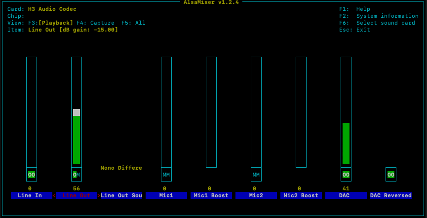
  15. I'm on an Orange PI PC running Armbian_23.08.0-trunk_Orangepipc_bullseye_edge_6.5.1_minimal I've enabled analog audio out the 3.5mm jack using overlays=analog-codec in /boot/armbianEnv.txt I'm connecting the analog 3.5mm jack to a 3watt amp & speakers. It works mostly, but I only get audio on the left channel. Alsa mixer Line Out only allows one channel to be unmuted at a time - left channel or right channel. Left channel sounds pretty good (DAC reversed appears to increase dynamic output). Right channel is very low volume and appears to be "squelched" - is the audio signal reversed from ground or something? Anyway, is there some way to get stereo output working similar to a USB sound card with stereo DAC? I'm currently connecting the left channel to both left/right inputs to my amp and that appears to be working well. Any audiophiles out there get stereo working through the 3.5mm jack?
  16. After playing around with the dts and removing entries already defined in the kernel dts, I got it to compile and install and run without errors. /dts-v1/; /plugin/; / { compatible = "allwinner,sun8i-h3"; fragment@1 { target = <&pio>; __overlay__ { spi0_cs1_pin: spi0-cs1-pin { pins = "PA21"; function = "spi0"; }; ili9341_rst: ili9341-rst { pins = "PA7"; function = "gpio_out"; }; ili9341_dc: ili9341-dc { pins = "PA8"; function = "gpio_out"; }; ili9341_led: ili9341-led { pins = "PA9"; function = "gpio_out"; }; ads7846_pin: ads7846-pin { pins = "PA10"; function = "irq"; }; }; }; fragment@2 { target = <&spi0>; __overlay__ { #address-cells = <1>; #size-cells = <0>; pinctrl-names = "default"; pinctrl-0 = <&spi0_pins>; status = "okay"; ili9341: ili9341@0 { compatible = "ilitek,ili9341"; reg = <0>; pinctrl-names = "default"; pinctrl-0 = <&spi0_cs0_pin>; status = "okay"; spi-max-frequency = <16000000>; rotate = <90>; bgr; fps = <25>; buswidth = <8>; regwidth = <16>; reset-gpios = <&pio &ili9341_rst 0>; dc-gpios = <&pio &ili9341_dc 0>; led-gpios = <&pio &ili9341_led 0>; }; xpt2046: xpt2046@1 { compatible = "ti,ads7846"; reg = <1>; pinctrl-names = "default"; pinctrl-0 = <&spi0_cs1_pin>; interrupts = <&ads7846_pin>; interrupt-parent = <&pio>; status = "okay"; spi-max-frequency = <1000000>; }; }; }; }; [ 5.778467] fbtft: module is from the staging directory, the quality is unknown, you have been warned. [ 5.792958] fb_ili9341: module is from the staging directory, the quality is unknown, you have been warned. that's all I hear from it in the system logs. The display doesn't light up, and I don't see a new frame buffer /dev/fb1 for the LCD display. I'm not sure if it is working or not. I assume there are more things I need to do to activate the display and make it the console screen? Thanks for all the help so far. I feel I'm getting close to getting this display to work.
  17. I think the overlay is trying to implement 2 CS pins for SPI0. I think OrangePI PC only has one SPI port exposed to the header pins. Does the 2 CS logic look OK in the DTS?
  18. So, I built the latest version of armbian edge and generated Armbian_23.08.0-trunk_Orangepipc_bullseye_edge_6.5.1_minimal.img. I modified the kernel to include the drivers for Hosyond 2.8 Inches TFT LCD Touch Screen Shield Display Module 320x240 SPI Serial ILI9341 with Touch Pen - modules fbtft and fb_ili9341 Pinout for the SPI display <==> OrangePi PC : 1 - VCC (1) 3.3v 2 - GND (6) GND 3 - CS (24) SPI0 CS 4 - RESET (29) GPIO 21 5 - DC (31) GPIO 22 6 - SDI (MOSI) (19) SPI0 MOSI 7 - SCLK (23) SPI0 CLK 8 - LED (33) GPIO 23 9 - SDO (MISO) (21) SPI0 MISO 10 - T_CLK (23) SPI0 CLK 11 - T_CS (21) GPIO 11 12 - T_DIN (19) SPI0 MOSI 13 - T_DO (21) SPI0 MISO 14 - T_IRQ (35) GPIO 24 I found an example dts for a similar device: touchscreen.dts /dts-v1/; /plugin/; / { compatible = "allwinner,sun4i-a10", "allwinner,sun7i-a20", "allwinner,sun8i-h3", "allwinner,sun50i-a64", "allwinner,sun50i-h5"; fragment@0 { target-path = "/aliases"; __overlay__ { spi0 = "/soc/spi@5010000"; spi1 = "/soc/spi@5011000"; }; }; fragment@2 { target = <&r_pio>; __overlay__ { spi0_cs1_pin: spi0_cs1_pin { pins = "PA21"; function = "gpio_out"; output-high; }; }; }; fragment@3 { target = <&spi0>; __overlay__ { pinctrl-names = "default", "default"; pinctrl-1 = <&spi0_cs1_pin>; cs-gpios = <0>, <&r_pio 0 21 0>; /* PA21 */ status = "okay"; debug = <0>; #address-cells = <1>; #size-cells = <0>; spidev@0 { reg = <0>; /* Chip Select 0 */ compatible = "spidev"; spi-max-frequency = <100000000>; status = "disabled"; }; spidev@1 { reg = <1>; /* Chip Select 1 */ compatible = "spidev"; spi-max-frequency = <12000000>; status = "disabled"; }; }; }; fragment@4 { target = <&pio>; __overlay__ { ili9341_pins: ili9341_pins { pins = "PA7", "PA8"; /*RESET, DC_RS*/ function = "gpio_out", "gpio_out" ; }; }; }; fragment@5 { target = <&spi0>; __overlay__ { /* needed to avoid dtc warning */ #address-cells = <1>; #size-cells = <0>; cs-gpios = <0>, <&r_pio 2 3 0>; /* PC3 */ status = "okay"; ili9341: ili9341@0 { compatible = "ilitek,ili9341"; spi-max-frequency = <32000000>; reg = <0>; pinctrl-names = "default"; pinctrl-0 = <&ili9341_pins>; status = "okay"; debug = <0>; txbuflen = <32768>; rotate = <90>; bgr; fps = <60>; buswidth = <8>; regwidth = <16>; reset-gpios = <&pio 0 7 0>; /*RST= PA7 */ dc-gpios = <&pio 0 8 0>; /*LCD_RS PA8 */ init = <0x1000001 0x2000005 0x1000028 0x10000cf 0x00 0x83 0x30 0x10000ed 0x64 0x03 0x12 0x81 0x10000e8 0x85 0x01 0x79 0x10000cb 0x39 0x2c 0x00 0x34 0x02 0x10000f7 0x20 0x10000ea 0x00 0x00 0x10000c0 0x26 0x10000c1 0x11 0x10000c5 0x35 0x3e 0x10000c7 0xbe 0x100003a 0x55 0x1000036 0x28 0x10000b1 0x00 0x1b 0x1000026 0x01 0x10000f2 0x08 0x1000026 0x01 0x10000e0 0x1f 0x1a 0x18 0x0a 0x0f 0x06 0x45 0x87 0x32 0x0a 0x07 0x02 0x07 0x05 0x00 0x10000e1 0x00 0x25 0x27 0x05 0x10 0x09 0x3a 0x78 0x4d 0x05 0x18 0x0d 0x38 0x3a 0x1f 0x10000b7 0x07 0x10000b6 0x0a 0x82 0x27 0x00 0x1000011 0x2000064 0x1000029 0x2000064>; }; xpt2046: xpt2046@1 { compatible = "ti,ads7846"; reg = <1>; status ="okay"; spi-max-frequency = <1000000>; interrupts = <0 10 2>; /* PA10 high-to-low edge triggered */ interrupt-parent = <&r_pio>; /* PA10<-----> TP_IRQ */ pendown-gpio = <&r_pio 0 10 0>; ti,keep-vref-on = <1>; ti,x-min = /bits/ 16 <00>; ti,x-max = /bits/ 16 <0xFFF>; ti,y-min = /bits/ 16 <00>; ti,y-max = /bits/ 16 <0xFFF>; ti,x-plate-ohms = /bits/ 16 <60>; ti,pressure-max = /bits/ 16 <255>; ti,swap-xy = <0>; }; }; }; }; sudo armbian-add-overlay touchscreen.dts sudo nano /etc/modules-load.d/fbtft.conf fbtft fb_ili9341 There are problems with the overlay, not sure how to define the pin PA21 so it can be recognized: [ 1.627208] [drm] Initialized sun4i-drm 1.0.0 20150629 for display-engine on minor 0 [ 1.647806] Console: switching to colour frame buffer device 90x30 [ 1.668235] sun4i-drm display-engine: [drm] fb0: sun4i-drmdrmfb frame buffer device [ 1.669024] sun8i-h3-r-pinctrl 1f02c00.pinctrl: unknown pin PA21 [ 1.669041] sun6i-spi 1c68000.spi: there is not valid maps for state default [ 1.669130] sun8i-h3-pinctrl 1c20800.pinctrl: supply vcc-pc not found, using dummy regulator [ 1.669640] sun6i-spi 1c68000.spi: cannot register SPI master [ 1.674905] sun8i-h3-r-pinctrl 1f02c00.pinctrl: supply vcc-pl not found, using dummy regulator [ 1.677031] sun8i-h3-pinctrl 1c20800.pinctrl: supply vcc-pf not found, using dummy regulator [ 1.678053] sun8i-h3-r-pinctrl 1f02c00.pinctrl: unknown pin PA21 [ 1.678081] sun6i-spi 1c68000.spi: there is not valid maps for state default [ 1.678158] sun8i-h3-pinctrl 1c20800.pinctrl: supply vcc-pc not found, using dummy regulator [ 1.678604] sun6i-spi 1c68000.spi: cannot register SPI master [ 1.678903] sunxi-mmc 1c0f000.mmc: Got CD GPIO [ 1.683732] sun8i-h3-pinctrl 1c20800.pinctrl: supply vcc-pg not found, using dummy regulator [ 1.685245] sun8i-h3-r-pinctrl 1f02c00.pinctrl: unknown pin PA21 [ 1.685267] sun6i-spi 1c68000.spi: there is not valid maps for state default [ 1.685343] sun8i-h3-pinctrl 1c20800.pinctrl: supply vcc-pc not found, using dummy regulator [ 1.685647] sun6i-spi 1c68000.spi: cannot register SPI master [ 1.687568] phy phy-1c19400.phy.0: Changing dr_mode to 1 [ 5.889192] fbtft: module is from the staging directory, the quality is unknown, you have been warned. [ 5.896204] fb_ili9341: module is from the staging directory, the quality is unknown, you have been warned. [ 5.896447] fb_ili9341: unknown parameter 'debug' ignored Any advice would be helpful.
  19. I installed the debs, but I don't see the modules or overlays for the touchscreen for orangepi pc. sudo dpkg -i linux-headers-edge-sunxi_6.4.14-Armbian.23.10_armhf.deb sudo dpkg -i linux-image-edge-sunxi_6.4.14-Armbian.23.10_armhf.deb sudo dpkg -i linux-libc-dev_6.4.14-Armbian.23.10_armhf.deb which overlays need to be used in armbianEnv.txt? which modules need to be loaded? Are there any arguments needed for the modules?
  20. Thanks for the debs! I'll try them out and get that display working. I'm also trying to get this one working too: 3.5 inch LCD HDMI USB Touch Screen Real HD 1920x1080 LCD Display Py for Raspberri 3 Model B / Orange Pi (Play Game Video)MPI3508 https://www.aliexpress.us/item/3256805680215131.html?spm=a2g0o.order_detail.order_detail_item.3.38aff19cCzHh5K&gatewayAdapt=glo2usa The HDMI works great, and the hat for the touch interface is almost perfect for Orange PI PC (CS pin is second SPI CS select instead of the primary SPI CS, hence the original request in this post). I think the debs you linked should be able to drive this one too (sans the FBTFT).
  21. The display that requires dual SPI interfaces is: Hosyond 2.8 Inches TFT LCD Touch Screen Shield Display Module 320x240 SPI Serial ILI9341 with Touch Pen Compatible with Arduino R3/Mega2560 Development Board I bought it from Amazon. I can get it working for display only using FBTFT, but I haven't gotten the touch part to work yet. I was trying to get it working with an Orange PI Zero 2, but I switched to Orange PI PC because there were older images out there that I hoped would support touch drivers. I think it uses the same touch controller as my HDMI LCD touchscreen. Here is the link to the amazon page: https://www.amazon.com/gp/product/B09XHJ9KRX/ref=ppx_yo_dt_b_asin_image_o09_s00?ie=UTF8&th=1
  22. So, Find /. -name "*.dtbo" Find /. -name "*.dtb" Find /. -name "*.dts" doesn't turn up any of them in the factory install image. The modules that would be useful to the hardware I have available are: ILI7340 - 2.8 inch LCD + Touch ads7846 Controller - small LCD SPI display with touch (Dual SPI needed) sun8i-h3-spi-ads7846.dts - MPI3508 2.8 inch HDMI LCD with ads7846 touch controller (Single SPI needed) Unless there is a way to install overlays for the functionality using "apt install ..." I assume I will need to build a custom kernel. I've not built a custom kernel before. Where is the best place to build it? On the Orange PI itself or on my Mac? Is there a handy guide for the process? Thanks for all the assistance. I've downloaded spi-ads7846.dts and configured it for orange pc spi0.1 which should use second CS PIN 26 (PA21) (to the best of my knowledge) The pin for IRQ touch event is PA2 /dts-v1/; /plugin/; / { compatible = "allwinner,sun4i-a10", "allwinner,sun7i-a20", "allwinner,sun8i-h3", "allwinner,sun50i-a64", "allwinner,sun50i-h5"; fragment@0 { target = <&pio>; __overlay__ { ads7846_pins: ads7846_pins { pins= "PA2"; function = "irq"; }; }; }; fragment@1 { target = <&spi0>; __overlay__ { #address-cells = <1>; #size-cells = <0>; status = "okay"; ads7846@0 { compatible = "ti,ads7846"; reg = <1>; /* Chip Select 1 */ status = "okay"; pinctrl-names = "default"; pinctrl-0 = <&ads7846_pins>; spi-max-frequency = <2000000>; interrupt-parent = <&pio>; interrupts = <0 2 2>; /* PA2 IRQ_TYPE_EDGE_FALLING */ pendown-gpio = <&pio 0 2 0>; /* PA2 */ /* driver defaults, optional */ ti,x-min = /bits/ 16 <0>; ti,y-min = /bits/ 16 <0>; ti,x-max = /bits/ 16 <0x0FFF>; ti,y-max = /bits/ 16 <0x0FFF>; ti,pressure-min = /bits/ 16 <0>; ti,pressure-max = /bits/ 16 <0xFFFF>; ti,x-plate-ohms = /bits/ 16 <400>; }; }; }; }; I've compiled & copied to user overlays and updated armbianEnv.txt to use spi0.1: overlays=spi-add-cs1 spi-spidev user-overlays=spi-ads7846 param_spidev_spi_bus=0 param_spidev_spi_cs=1 This does about what you'd expect, creates spidev0.1 and no error messages in dmesg. However I still need to compile the touch driver and load it as a module. I can't do that because the apt repository doesn't have the headers: sudo apt install linux-headers-$(uname -r) Reading package lists... Done Building dependency tree... Done Reading state information... Done E: Unable to locate package linux-headers-6.1.47-current-sunxi E: Couldn't find any package by glob 'linux-headers-6.1.47-current-sunxi' Is there a way to get the linux-headers-6.1.47-current-sunxi.deb file?
  23. Great advice. I made the switch to the latest Armbian image Armbian_23.8.1_Orangepipc_bookworm_current_6.1.47 I was in the process of applying what I've done so far. Enabling dual SPI with the spi-double-spidev-cs user overlay does not work in this image (it didn't work on the other image properly either) I'll check out the binaries listed above and see if I can make them work for me. Thanks for all the advice! If I get it working, I'll paste a tutorial.
  24. I only get SPI0.0 when I enable SPI using spi-add-cs1 spi-spidev. It uses the wrong pin 24 by default for the CS. The LCD needs pin 26. I think it configured SPI0.1 properly for the LCD when I enable second CS for SPI0.1 using spi-double-spidev-cs. Using a scope I see pin 26 going low before clock/data go out the SPI pins. However, I'm not sure how to enable TP_IRQ pin interrupt for the touch interface on pin 22. I think I need to add DTS for the touch interface as well as use the ads7846_device module.
  25. The command dtc --sort -I fs -O dts /sys/firmware/devicetree/base > cur-dts-out.txt throws warnings and an exception and does not output any data in the text file: orangepi@orangepipc:~$ sudo dtc --sort -I fs -O dts /sys/firmware/devicetree/base > cur-dts-out.txt <stdout>: Warning (unit_address_vs_reg): /memory: node has a reg or ranges property, but no unit name .... <stdout>: Warning (graph_child_address): /soc/camera@1cb0000/port: graph node has single child node 'endpoint', #address-cells/#size-cells are not necessary Segmentation fault The DTB used in this image is /boot/dtb/sun8i-h3-orangepi-pc.dtb The sections you referenced are pinctrl@1c20800 { spi0-pins { pins = "PC0\0PC1\0PC2\0PC3"; function = "spi0"; phandle = < 0x16 >; }; spi1-pins { pins = "PA15\0PA16\0PA14\0PA13"; function = "spi1"; phandle = < 0x17 >; }; } spi@1c68000 { compatible = "allwinner,sun8i-h3-spi"; reg = < 0x1c68000 0x1000 >; interrupts = < 0x00 0x41 0x04 >; clocks = < 0x03 0x1e 0x03 0x52 >; clock-names = "ahb\0mod"; dmas = < 0x15 0x17 0x15 0x17 >; dma-names = "rx\0tx"; pinctrl-names = "default"; pinctrl-0 = < 0x16 >; resets = < 0x03 0x0f >; status = "disabled"; #address-cells = < 0x01 >; #size-cells = < 0x00 >; phandle = < 0x5c >; }; spi@1c69000 { compatible = "allwinner,sun8i-h3-spi"; reg = < 0x1c69000 0x1000 >; interrupts = < 0x00 0x42 0x04 >; clocks = < 0x03 0x1f 0x03 0x53 >; clock-names = "ahb\0mod"; dmas = < 0x15 0x18 0x15 0x18 >; dma-names = "rx\0tx"; pinctrl-names = "default"; pinctrl-0 = < 0x17 >; resets = < 0x03 0x10 >; status = "disabled"; #address-cells = < 0x01 >; #size-cells = < 0x00 >; phandle = < 0x5d >; }; __symbols__ { pio = "/soc/pinctrl@1c20800"; spi0_pins = "/soc/pinctrl@1c20800/spi0-pins"; spi1_pins = "/soc/pinctrl@1c20800/spi1-pins"; spi0 = "/soc/spi@1c68000"; spi1 = "/soc/spi@1c69000"; }
×
×
  • Create New...

Important Information

Terms of Use - Privacy Policy - Guidelines