forumtrekker
-
Posts
11 -
Joined
-
Last visited
-

Driving the ili9488 LCD (4.0 inch cheap chinese clone)
forumtrekker replied to robertoj's topic in Allwinner sunxi
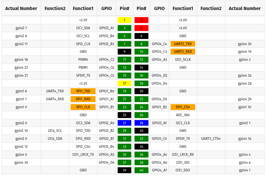
Pami, I have not personally found any LLM capable of generating working DTS files no matter what. It seems to be too niche for the LLM to understand. This DTS could potentially be a good starting ground for the pi, replacing "bcm2835" which refers to the pi zero 1, with "bcm2710" which refers to the pi zero 2. The github repository I linked is a good guide to getting the red displays working for a voron printer using panel-mipi driver, and I referenced it to create the DTS I use for the rock pi 4b. Also, try lowering the SPI speed to 20, 16, or 10 MHz, then raise it when you verify it works. I was frustrating myself for weeks thinking my DTS was broken, when it was fine the entire time, just my SPI speed was too high. robertoj: I appreciate your help, but I believe the issue I have with the red display (I have the same one as pami sent) is a combination of SPI commands being sent at the wrong interval (at the end of the clock cycle instead of in line), as well as insufficient SPI speed - where the display freezes above 24 MHz, and shows extreme visual tearing below it. At RGB666, its too much data for a measly 20MHz SPI rate, and the board does not support any other RGB modes in SPI. Since the TE pin is not exposed on the board, I cannot sync the SPI writes to the display. At least, that is my theory. I've given up on using an SPI display, and instead transitioned to an RGB Parallel display, which uses one gpio pin per color bit. Note that, at least in the display datasheet I received, the display actually does have the pins needed to drive it over DPI RGB Parallel. You can drive the board in 16, 18, or 24 bit mode over DPI RGB Parallel. These pins are not exposed on the board, but you could use an FPC breakout board to interface with these pins, and drive the display in DPI RGB parallel instead (accounting for the backlight voltage needed). The advantage of using RGB Parallel is it natively uses the GPU (RGB Parallel is the same technology as VGA) and has very fast refresh rate. For anyone here in future, any DPI hats that exist, like the adafruit kippah or othermod dpi topper, do not have the correct pinout to interface with this specific ili9486/8, but if you were to rearrange the pins on either the HATS or with an intermediary FPC PCB, then they would work plug and play. -
Critique or improve my method to get a lightweight LabWC desktop
forumtrekker replied to robertoj's topic in Allwinner sunxi
With modifications to lightdm.conf I got lightdm working with your tutorial, however lightdm and labwc don't seem to use the SPI display. I verified the setup works on an HDMI screen (with a large box of random color artifacts filling the right quarter side, but that's hopefully just because it was a TV I tested with. I don't really care about HDMI). Do i need to specify lightdm / labwc to use the /sys/class/drm/card0-SPI-1? I'm curious if you simply launched LightDM and had it use the SPI display by default, without changing any configurations (as that is what it sounds like you achieved) I'm realizing I don't know enough about how wayland works to even know how to start debugging the issue or getting it to use the tinydrm device or even the legacy framebuffer device it adds for compatibility. Maybe I need to get Raspbian running and copy their configuration files, since Raspbian Trixie runs on wayland. The only difference between your guide and my setup is I am running kernel 6.18, as I can't seem to find how to compile or install kernel 6.13. Available installable kernels are 6.12, 6.14, and 6.18 as of 26.0.2 Armbian Trixie. The steps you outline in the github repo work with some modification, namely I will edit to include the lightdm.conf when I get home, since it requires modification from the original installed version. Further, certain packages are uninstallable, or named differently than in your guide. Here is the one line APT command to install all the packages you list, with the package names fixed. Certain packages don't seem to be required at all - namely freerdp, providing the windows equivalent of VNC, so its not included in this list. There are likely others and I assume you collected these packages to install from multiple guides / forums, so the inconsistencies are understandable. sudo apt install libcairo2-dev libpango1.0-dev libxml2-dev libglib2.0-dev libdisplay-info-dev hwdata libgbm-dev libdisplay-info-dev libseat-dev libinput-dev libpango1.0-dev libpangocairo-1.0-0 libcairo2-dev libglib2.0-dev libpixman-1-dev libxkbcommon-dev liblcms2-dev libxcb-xinput-dev libxcb-errors-dev libxcb-render-util0-dev libxcb-present-dev libxcb-res0-dev libxcb-dri3-dev libxcb-ewmh-dev libxcb-icccm4-dev libxcb-composite0-dev cmake libxml2-dev libliftoff-dev build-essential cmake libwayland-dev wayland-protocols libegl1-mesa-dev libgles2-mesa-dev libdrm-dev libgbm-dev libinput-dev libxkbcommon-dev libudev-dev libpixman-1-dev libsystemd-dev libcap-dev libxcb1-dev libxcb-composite0-dev libxcb-xfixes0-dev libxcb-xinput-dev libxcb-image0-dev libxcb-render-util0-dev libx11-xcb-dev libxcb-icccm4-dev libwinpr3-dev libpng-dev libavutil-dev libavcodec-dev libavformat-dev universal-ctags expat libexpat1 libexpat1-dev seatd foot librsvg2-dev scdoc gettext appmenu-gtk-module-common libaccountsservice-dev gir1.2-accountsservice-1.0 liblightdm-gobject-dev liblightdm-gobject-1-0 libgtk-3-dev gnome-common nasm meson I am running Armbian Trixie, and I did not need to install any packages from trixie-backports or oldstable-backports to get your setup to work properly. EDIT: It actually seemed to be my SPI clock speed was too high for the display. Lowering it to a conservative 16 or 20 MHz gets labwc to work, without having to configure and specify the display to output on. -
Driving the ili9488 LCD (4.0 inch cheap chinese clone)
forumtrekker replied to robertoj's topic in Allwinner sunxi
Will comment on the new thread, since the initial question of driving SPI displays with tinyDRM has been answered. Although, I'm starting to wonder if the kungfupancake modifications are inadequate for my display, since I still cannot get a full plymouth boot log to display (it seems to "run off the screen" a little at some point then just stop). Maybe its overflowing some buffer or the display is mis-sized or something and the screen is attempting to display physically off the screen? I don't really know. I might need to peruse LCDwiki to find other init commands. Edit: Actually it seems to be the SPI speed. A conservative 16 or 20 MHZ gets the display working, with significantly unusable screen tearing any higher than that. I have a direct jumper connection but my jumper cables are pretty long (about 20 cm) and some are crossed over, which might mean there is some interference. Will try shortening, since the low 16 or 20 MHz speed has very low FPS rates. It is strange because your display seems to work on 40MHz Edit 2: The ili9488 data sheet indicates it can use 16, 18, and 24 bit color modes, however attempting to use 16 bit (r5g6r5 on the format line) results in a worse tearing and garbled messes. Looks like it is over DPI or DSI only, not SPI. Also in the data sheet is indicatons that 20 MHz is the max framerate, explaining why higher rates are unstable. Should have read the data sheet! Everything seems to be working according to the hardware specifications, so squeezing more framerate is seeing if panel-mipi is capable of partial updates or seeing if I can up the data bus width.0 Edit 3: Confused again, because later in the data sheet, SPI mode states 8 colors (R1G1B1), 65k colors (R5G6B5) and 262K colors (R6G6B6) are supported, yet panel-mipi states only 666 is supported. Running 565 under panel-mipi shows the artifacts and tearing making it unusable, and trying 111 results in a white screen. This forum implies the LCD CAN use 565 mode. I'm quite confused, and this has probably become the wrong forum for this discussion? https://forum.clockworkpi.com/t/lcd-ili9488-really-doesnt-support-565-rgb-mode/16573 Edit 4: This github thread indicates that the datasheet is in error, and does NOT support 565 color, so looks like this display is restricted to 9-12 fps. Bummer. https://github.com/notro/panel-mipi-dbi/issues/2 Edit 5: This thread shows some ili9488 can work on 16 bit 565 mode?? Will try messing with panel-mipi init codes, but maybe this only applies for microcontrollers. https://forum.clockworkpi.com/t/ideas-for-improving-lcd-speed/17159/16 Edit 6: The MIPI DBI states the following formats, taken from this site: Coupled with editing the init line from 18 bit to 16 or 3 bit color mode, in accordance to the thread I linked in edit 5 . Still, yields no different results: it actually seems like editing the color init line in the bin file does nothing, and what actually matters is the color format specified in the DTS. R5G6B5 still shows garbled mess, and any of the four 3 bit color modes only shows a white screen.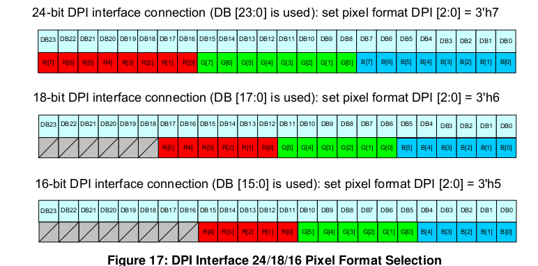
-
Driving the ili9488 LCD (4.0 inch cheap chinese clone)
forumtrekker replied to robertoj's topic in Allwinner sunxi
Did a fresh install of community Armbian desktop this time, running current 6.12.60 from here. It seems there is no need to compile from scratch if you are using the panel-mipi driver from kungfupanda, I copied my DTS, panel-mipi.bin, etc. from my edge custom compiled installation to the community one and it worked fine after repeating the initramfs process, but I still get a stuck display after a bit, this time on the Armbian loading screen. SSH and Serial console work fine, its just the system stops knowing how to use the display after the initial boot sequence is done, and the kernel hands off the display to X11 / Wayland? This is consistent with how I believe tinydrm works, which is storing the image in memory and displaying new ones from memory if given (which in this case, none are given after a certain stage in the boot process and this hand off to the window manager never happens.) Need to figure out how to tell the system to keep using the drm display. I already tried putting /dev/dri/card0 instead of /dev/fb0 in 99-fbdev.conf, and I've been trying the following extraarg in /boot/armbianEnv.txt to try and get it to work. Screen still pauses halfway through boot messages / loading screen. extraargs=video=SPI-1:480x320@30 -
Driving the ili9488 LCD (4.0 inch cheap chinese clone)
forumtrekker replied to robertoj's topic in Allwinner sunxi
I got the display to work! I left out a phandle = <0x01> line in my ili9486@0 section, adding it made it work. DTS was fine otherwise. It's a little glitchy and laggy so I need to tinker with it more, but I see plymouth displaying properly! I can't seem to get into tty or XFCE, but I believe I'm not running wayland and it sounds like thats a requirement for tinydrm? I'll figure it out, but the hard part is over. Once I get everything polished I'll write a summary of my steps so its easy for others to follow. Working DTS for the red ili9488 display using tinydrm driver: Edit: Removing XFCE & plymouth seems to break things, display is pure white again. It also rearranges /sys/class/drm to be card1-SPI-1 instead of card0-SPI-1. Adding this line to /boot/armbianEnv.txt results in the blue and black stripes again, instead of a white screen, but prevents the screen from working with plymouth or XFCE. extras="fbcon=map:0" Reinstalling plymouth and XFCE reverts this white screen and shows boot messages again but no tty console, only if there is no fbcon line at all. Installing just plymouth and not XFCE shows boot messages only if fbcon=map:1 is set, note the 1 instead of 0. Still no tty. The last boot message is and the one after (which I see on serial console) is this, so maybe plymouth finishes writing boot messages to display and the system just never accesses it again? Maybe I need xorg to access /dev/dri/card0 instead of /dev/fb0, since it is not a fbtft device but a DRM one? [ OK ] Finished plymout… Write Out Runtime Data. -
Driving the ili9488 LCD (4.0 inch cheap chinese clone)
forumtrekker replied to robertoj's topic in Allwinner sunxi
My latest post on page two shows the waveshare clone LCD DTS, working under FBTFT not DRM. The gpio formatting is strange, but it is what I lifted from Radxa provided DTS for a different waveshare LCD that I'm adapting for the displays here. This DTS I have is functional, and I'm certain the pins are correct as the Red ili9488 display shows purple / blue lines using FBTFT (probably incorrect init sequence, since it shows purple and red using your FBTFT init sequence under ili9341 driver instead of ili9486. fb_ili9486 does not work as you also experienced), and the Blue waveshare clone display works perfectly. Current working red DTS: Current working waveshare fbtft, laggy (waveshare LCD is a parallel display with shift register hacks and kind of bad, so lag is expected.) Haven't tried DMA or fbcp since fbtft is outdated anyway. I've commented what each line / hexadecimal represents, to make it easy to follow. I spent several weeks trying variations of the DTS you provided, and I was never able to get it to work properly. I only got positive results when I started using the formatting I am now. The formatting is semi-understandable, every gpio and spi is just referenced at the end of the file by line name and position in increases of 4 (0 refers to the first item in a line, 4 to the second, 8 to the third etc), instead of being directly called in their location. For example, the target of fragment0 is 0xfffffff, which at the bottom of the DTS in the fixups section, is referred to as spi1. The cs-gpios are referred to in fixups in both gpio4 and gpio1. I am using latest armbian compiled per your instructions / forum posts, running edge compiled armbian with kernel 6.18.0-rc6, with panel-mipi selected at kernel build time according to the KungfuPancake github, firmware placed in lib/firmware, and drm verified to be loaded and semi functioning. I've essentially followed all your forum posts but have not had the success you have had. I'm now wondering if I have to tell armbian how to use the display with DRM, because I read somewhere that fbtft will draw constantly to your screen, but DRM will only draw when called and by default stays a white screen until called by the system. I tried adding a line in /boot/armbian.conf which should use the /dev/fb0 device as a display when /sys/class/drm/card1-spi is present (which it is), but it doesn't change anything. Edit: it seems adding this is not necessary if plymouth is installed. extras="fbcon=map:1" I appreciate your help! EDIT: I went through the first page of this thread again to check I haven't missed anything. since I've done multiple reinstall's etc... and realized after installing xfce this time, I didn't go through the updating of initramfs to ensure panel-mipi loads properly with plymouth installed. Panel-mipi seemed to still load fine and be present, but I went through the steps in your thread here and it fixed the following error I was having since installing XFCE, AND the screen is showing blue and black bars. The evidence seems to be pointing to the drm driver being initialized and used properly, so i'm going to make sure my gpio pin polarity is correct in my DTS since DRM expects flipped values in some cases compared to FBTFT, then I will check my wiring and shorten them in case it is physics / interference problem, and finally I'll try other init sequences from lcdwiki. [ 4.601941] panel-mipi-dbi-spi spi1.0: No config file found for compatible 'panel-mipi-dbi-spi' (error=-2) -
Driving the ili9488 LCD (4.0 inch cheap chinese clone)
forumtrekker replied to robertoj's topic in Allwinner sunxi
I think I have a partial success but I'm struggling to get anything but white on the red display! Will update when I have more results. panel-mipi is loading, and Card-1-SPI appears under /sys/class/drm/ which is very promising. Verified that /lib/firmware/panel-mipi-dbi-spi is still present, still patched with Kungfupancake's init, and is loaded according to lsmod (as well as dmesg) My current DTS: Edit: I installed XFCE to test, and strangely this has caused dmesg to throw errors related to panel-mipi. I had these same errors when panel-mipi was missing from /lib/firmware but it is still present there. -
Driving the ili9488 LCD (4.0 inch cheap chinese clone)
forumtrekker replied to robertoj's topic in Allwinner sunxi
Good to know. I'm interested in getting the red LCD's to work as they are cheaper and more available, I purchased the waveshare only to test my SPI, SBC, and DTS formatting were functional. Now that I confirmed how to translate DTS to work with my SBC, I can work on the red ili9486/8 without worrying about it being a formatting issue. -
Driving the ili9488 LCD (4.0 inch cheap chinese clone)
forumtrekker replied to robertoj's topic in Allwinner sunxi
I went out and bought a waveshare clone 3.5 inch display, to try and confirm I haven't spent the last few weeks trying to do the impossible with broken GPIO pins or something - and got a partial success eventually, using fbtft, displaying basic console and plymouth boot logs. It has poor fps like you said - which I expected, its the reason I tried to use the tiny DRM driver from the beginning, but now I know the rockpi and DTS is functional. The same DTS also shows a broken, purple / blue output of bars on my red ili9488 display only if I adjust the bus width to 16 instead of 8 (0x10, instead of 0x08), otherwise it remains a blank white screen. A bus width of 18 and 24 also only gave me a white screen, so 16 might be correct. I've been unable to confirm touch works, since I only have a basic console and I can't figure out how to start LXDE on a framebuffer device, but I do see messages insinuating it initializes under dmesg | grep spi. I could probably just query the GPIO interrupt to find out if touch is working. Not that important right now. I did realize that the big "fixups" section at the bottom is clearly used to replace the empty 0xfffffff targets throughout. I'm unsure why the DTS was written this way, but it works so I am not going to touch it (changing the targets and switching from hex to decimal values broke the DTS for some reason.) Unfortunately, a simple drop in replacement of fb_ili9486 with panel_mipi_dbi did not make either display work, even with the added arguments you use in your latest DTS. Clearly I have much more work to do. BUT I've finally confirmed the DTS works, and all GPIO is claimed and SPI is initialized for both displays (even if the red LCD is showing gibberish), so now I need to nail down the subtle differences with the displays like the bus and reg width and find the right combo of spi clock speed, reg bus widths, and buffer length to get it all to work with fbtft (if only aliexpress sellers put up datasheets or example code!). Then I can follow the second half of your journey to hopefully translate a working fbtft setup to a panel_mipi_dbi setup. Maybe get backlight PWM working. All this still on edge kernel 6.18, on a rockpi 4b plus. -
Driving the ili9488 LCD (4.0 inch cheap chinese clone)
forumtrekker replied to robertoj's topic in Allwinner sunxi
Thanks for the reply! I'll address everything one by one: I am using the generic red ili9488 3.5inch TFT available everywhere, in this case at this link. I also have a generic red ili9341 2.4 inch TFT I purchased years ago to also test with. Neither seem to work with the DTS. It is definitely not the blue 3.5 inch waveshare screen which looks significantly different. Yes, uboot messages through serial console confirm my dtbo is found and applied without errors. No FDT errors. Applying user provided DT overlay spi1-correctedgpio.dtbo panel-mipi-dbi.ko exists in /lib/modules on the custom compiled armbian running kernel 6.18, but not on the unmodified armbian provided image running kernel 6.12. When building armbian for panel-mipi I confirmed it was selected and it was marked "M" according to the github instructions. Here's the interesting one - basically every GPIO is unclaimed including the ones I have hooked up for the display when doing Here's the link to the rock3c DTS I'm referencing. The Rock 3 pins are named very differently so I translated as best as I could to my rock 4, but I believe they are correct as I found that Radxa distributes a waveshare clone DTS for the rock pi 4 and the pins are named as I have named them. I've pasted the waveshare clone DTS distributed by Radxa below for reference. Using MOSI and MISO do not work, and according to the waveshare DTS I should be using spi_tx and spi_rx. Will continue trying MISO and MOSI in future edits though as it doesn't hurt. You mentioning the waveshare display made me look into the DTBO distributed by radxa OS, I copied it to armbian and tried using it with the red display, and while it expectedly does not work, the pins I expect show up EXCEPT for touch IRQ, which is still unclaimed. I labelled touch, DC/RS, and reset pins for ease of reading in parenthesis. This makes me think I might have success formatting your ili9486 DTS to be similar with the waveshare DTS to get panel-mipi-dbi working on my red LCD. I get dmesg messages so its definitely closer. Here's the full waveshare DTS, note because I decompiled the DTBO with the dtc command, it looks like it lost the target pointers so I'm unsure (but can guess) what they point to. The GPIO pins are also lost but I know what pins they refer to as their pin number is in hex and I can narrow them down to the only pins available according to the pinout diagram. This doesn't affect the DTBO function as I paste the DTBO directly without decompiling, so in theory that should be unchanged and fully functional. At the very least, it claims the GPIO correctly. -
Driving the ili9488 LCD (4.0 inch cheap chinese clone)
forumtrekker replied to robertoj's topic in Allwinner sunxi
Hello! First of all, thank you robertoj for this treasure trove of information - truly, I searched so much of the internet before finding this, because seemingly nobody is sharing DTS files for tft screens at all that aren't on a raspberry pi (which uses a different system afaik). I am using a rockpi 4bplus, trying to get an ili9488/86 tft screen to work, and struggling. I've used your latest DTS from page 1, using panel-mipi, verified it loads into initramfs using your other threads, compiled my own armbian edge on kernel 6.18 (and tried on kernel 6.12), corrected all FDT err not found errors on the DTS for my use case (my gpio numbers were out of scope)... still, all I get on my display is a blank white screen with no dmesg errors or comments about spi, panel etc... ;-; Not sure what else to try at this point. I'll post my files below, along with translated gpio pin numbers: /dts-v1/; /plugin/; /{ compatible = "radxa,rockpi4b-plus", "radxa,rockpi4", "rockchip,rk3399"; fragment@0 { target = <&spi1>; __overlay__ { #address-cells = <1>; #size-cells = <0>; pinctrl-names = "default"; /* new for linux 6.13 */ pinctrl-0 = <&spi1_clk &spi1_cs0 &spi1_rx &spi1_tx>; /* new for linux 6.13 */ cs-gpios = <&spi1_cs0>, <&gpio4 26 0>; /* lcd, touch chip select */ panel: panel@0 { compatible = "panel-mipi-dbi-spi"; status = "okay"; reg = <0>; spi-max-frequency = <40000000>; width-mm=<84>; height-mm=<56>; reset-gpios = <&gpio4 29 1>; /* taken from rock3c setup, then modified for armbian */ dc-gpios = <&gpio4 28 0>; /* 1 is low, 0 is high */ write-only; format = "b6x2g6x2r6x2"; panel-timing { hactive = <480>; vactive = <320>; hback-porch = <0>; vback-porch = <0>; clock-frequency = <0>; hfront-porch = <0>; hsync-len = <0>; vfront-porch = <0>; vsync-len = <0>; }; }; ads7846: ads7846@1 { compatible = "ti,ads7846"; reg = <1>; pinctrl-names = "default"; spi-max-frequency = <1000000>; interrupt-parent = <&gpio4>; interrupts = <21 2>; /* 2 is IRQ_TYPE_EDGE_FALLING pendown-gpio = <&gpio4 21 0>; /* same as interrupt, pulled high */ vcc-supply = <&vcc5v0_sys>; /* Fill in the voltage according to the actual power supply c> /* OPTIONS */ ti,x-min = /bits/ 16 <0>; ti,y-min = /bits/ 16 <0>; ti,x-max = /bits/ 16 <0XFFF>; ti,y-max = /bits/ 16 <0XFFF>; ti,pressure-min = /bits/ 16 <0>; ti,pressure-max = /bits/ 16 <0XFFF>; ti,x-plate-ohms = /bits/ 16 <400>; ti,swap-xy = <1>; }; }; }; };