

edupv
-
Posts
30 -
Joined
-
Last visited
Content Type
Forums
Store
Crowdfunding
Applications
Events
Raffles
Community Map
Posts posted by edupv
-
-
I tried this image : Armbian_5.89.190626_Nanopim4_Ubuntu_bionic_dev_5.1.0.7z, but the MAC address changes on every reboot, and so the IP address changes (auto IP).
-
On 12/21/2018 at 11:32 AM, edupv said:
For reference : btrfs raid 1 rsync writing speed
I just want to report that the writing speed from cwrsync (windows 10) to the btrfs raid 1 on NanoPo-M4 is 17MB/sec. (rsync option --info=progress2, during copying shows 21MB/sec, and then 17MB/sec when finished).
Note :
My 2 harddisks are on the same USB port (one enclosure contains two 2.5" hdd), not sure if each hdd on separated USB port will give better performance or not.
17-21MB/sec is the speed shown by cwrsync.
The dd command test results are as the following :
root@nanopim4:~# dd if=/dev/zero of=/bigdata/test1.img bs=1G count=1 oflag=dsync
1+0 records in
1+0 records out
1073741824 bytes (1.1 GB, 1.0 GiB) copied, 30.4417 s, 35.3 MB/s
root@nanopim4:~# dd if=/dev/zero of=/bigdata/test1.img bs=4G count=1 oflag=dsync
0+1 records in
0+1 records out
2147479552 bytes (2.1 GB, 2.0 GiB) copied, 33.0011 s, 65.1 MB/s
root@nanopim4:~# dd if=/dev/zero of=/bigdata/test1.img bs=4G count=2 oflag=dsync
dd: warning: partial read (2147479552 bytes); suggest iflag=fullblock
0+2 records in
0+2 records out
4294959104 bytes (4.3 GB, 4.0 GiB) copied, 56.6536 s, 75.8 MB/s
root@nanopim4:~# dd if=/dev/zero of=/bigdata/test2.img bs=512 count=1000 oflag=dsync
1000+0 records in
1000+0 records out
512000 bytes (512 kB, 500 KiB) copied, 2.01652 s, 254 kB/s
root@nanopim4:~#
More tests :
root@nanopim4:~# dd if=/dev/zero of=/bigdata/test1.img bs=2G count=2 oflag=dsync dd: warning: partial read (2147479552 bytes); suggest iflag=fullblock 0+2 records in 0+2 records out 4294959104 bytes (4.3 GB, 4.0 GiB) copied, 61.0895 s, 70.3 MB/s root@nanopim4:~# dd if=/dev/zero of=/bigdata/test1.img bs=2G count=1 oflag=dsync 0+1 records in 0+1 records out 2147479552 bytes (2.1 GB, 2.0 GiB) copied, 27.7552 s, 77.4 MB/s root@nanopim4:~# -
13 hours ago, NicoD said:
The 2 left USB3 ports or working over the same controller, so best to use one on the left, and one on the right. Then you can reach max speed on both together.
Read/Write speeds depend a lot on file sizes. Small files = slower.
17-21MB/s seems very slow. Is it using a USB3 to SATA adapter? Test what speed the hdd`s is capable of with big files. Then compare with the results you get here.
Thanks for your suggestion, but I have to use this enclosure that uses one USB port only.
Although 17-21MB/sec (for large files) shown by rsync is quite slow, it is not unacceptable for me, I use it for my backup files only. First time copy took quite a long time, but my daily/weekly change data is not so much, so daily/weekly update to the backup takes only 1-2 minutes or even shorter.
-
For reference : btrfs raid 1 rsync writing speed
I just want to report that the writing speed from cwrsync (windows 10) to the btrfs raid 1 on NanoPo-M4 is 17MB/sec. (rsync option --info=progress2, during copying shows 21MB/sec, and then 17MB/sec when finished).
Note :
My 2 harddisks are on the same USB port (one enclosure contains two 2.5" hdd), not sure if each hdd on separated USB port will give better performance or not.
-
14 minutes ago, chwe said:
or.. they're used for something else? e.g.
8	GPIO4_C1/I2C3_SCL(3V)
10	GPIO4_C0/I2C3_SDA(3V)
as long as i2c-3 is active those pins shouldn't do anything as gpio.. check DT to see if things are active..
May be yes, I don't know.
Anyway, I have tested all the above mentioned pins for output mode with a led (with a resistor in series, of course). The scripts is attached :
-
I think the correct formula for the port number is (32p + 8q + r) , where p, q, r are from the pin name GPIOp_qr. q is ABCD corresponding to 0123.
For example, pin# 8, GPIO4_C1, port number = (32x4 + 8x2 + 1) = 145.
All the port number of the 40 pins GPIO header with names GPIOp_qr :
PIN#   		Assignment	Port number			PIN#   		Assignment	Port number
====   		==========     	===========			====   		==========     	===========
 7		GPIO1_A0		32			 8		GPIO4_C1		145
11		GPIO1_A1		33			10		GPIO4_C0		144
13		GPIO1_A3		35			12		GPIO1_C2	 	 50
15		GPIO1_A4		36			16		GPIO1_C6	 	 54
								18		GPIO1_C7		 55
								22		GPIO1_D0		 56
								26		GPIO4_C5		149
I tested all the above pins for output mode with a led.
-
On 10/16/2018 at 7:45 PM, edupv said:
From here, you can check the pin names : http://wiki.friendlyarm.com/wiki/index.php/NanoPi_M4#Diagram.2C_Layout_and_Dimension.
I read somewhere, the formula of the port number is (32p + q + r) , where p, q, r are from the pin name GPIOp_qr. q is ABCD corresponding to 0123.
For example, the name of pin 7 is GPIO1_A0, the port number is 32 x 1 + 0 + 0 = 32.
I just checked the GPIO port numbers calculated by the above formula by using a led, only GPIO1_A0/1/3/4 are correct, other pins are all incorrect. Therefore, by the above formula, I know four port numbers only :
PIN# Assignment Port number ==== ========== =========== 7 GPIO1_A0 32 11 GPIO1_A1 33 13 GPIO1_A3 35 15 GPIO1_A4 36 -
On 10/16/2018 at 6:14 PM, oeydev said:
Thanks!
But how can I know pin number?
From here, you can check the pin names : http://wiki.friendlyarm.com/wiki/index.php/NanoPi_M4#Diagram.2C_Layout_and_Dimension.
I read somewhere, the formula of the port number is (32p + q + r) , where p, q, r are from the pin name GPIOp_qr. q is ABCD corresponding to 0123.
For example, the name of pin 7 is GPIO1_A0, the port number is 32 x 1 + 0 + 0 = 32.
Sorry, the above formula is incorrect, please read the following 2 posts.
-
3 hours ago, oeydev said:
Is armbian include RPi.GPIO package ?
How can I control GPIO?
If you are developing applications yourselves, you can consider the following generic gpio libraries :
python : https://github.com/derekstavis/python-sysfs-gpio
golang : https://github.com/brian-armstrong/gpio
They can be used in all the boards. From one board to another board needs only changing the gpio port numbers. (e.g. Physical pin 7 of gpio header, OrangePi port number is 6, you have to change the port number to 32 for a Nanopi-M4).
-
40 minutes ago, NicoD said:
How do you power the HDD? With a split usb cable? Is it in an enlosure?
Maybe soething wrong with the power supply of the enclosure, a broken diode or so???
Actually, it is a raid. https://www.unitek-products.com/product/usb-storage?view=product&id=197. I power it by using a micro-usb cable plugged into the DC IN socket of the enclosure, the other end of the cable plugged into a 5V USB PSU.
When the board is off, plugging the usb cable of the raid to the usb port of board (while type-c power supply cable unplugged) will not turn the board on.
However, when the board is powered on with both of the cables plugged in, unplugging the type-c power cable will not turn it off, it is still powered by the usb cable of the raid.
-
The USB port can keep the board running by supplying power ?
I have an external powered USB hard disk connected to my Nanopi-M4. Today, I did something wrong and I cannot connect to the board (as a headless server) through SSH, so I pulled the power cable to power down the board. However, the board kept running, and the green led kept flashing. It was powered down when I also unplugged the USB cable.
-
42 minutes ago, rufik said:
My OPI PC (mainline kernel) just freezes from time to time, it respond to ping but I cannot ssh into it (waiting forever for session then disconnects), services does not respond also. It looks like some OOM or similar problems, I cannot check it via serial console because it's remote location.
So I thought that watchdog would be nice there, just to reset board in such cases.If your OPi PC can respond to ping, then it is not freeze and watchdog will not reset it normally.
I think you have to check (for example) if the sshd is listening to the correct port/interface, the firewall rules etc. If your OPi PC is not directly connected to the internet, then you should also check the port forwarding rule of your router etc....
-
10 hours ago, rufik said:
How is your watchdog doing?
")
Does it work reliable over the time?
I think it is working fine.
However, watchdog will only function when system hangs, it does not function normally. Therefore, I said "I think".
-
2 hours ago, zador.blood.stained said:
It also has a description
config BTRFS_FS_CHECK_INTEGRITY
	bool "Btrfs with integrity check tool compiled in (DANGEROUS)"
	depends on BTRFS_FS
	help
	  Adds code that examines all block write requests (including
	  writes of the super block). The goal is to verify that the
	  state of the filesystem on disk is always consistent, i.e.,
	  after a power-loss or kernel panic event the filesystem is
	  in a consistent state.

	  If the integrity check tool is included and activated in
	  the mount options, plenty of kernel memory is used, and
	  plenty of additional CPU cycles are spent. Enabling this
	  functionality is not intended for normal use.

	  In most cases, unless you are a btrfs developer who needs
	  to verify the integrity of (super)-block write requests
	  during the run of a regression test, say N
You can read the btrfs FAQ to start with
Thanks for your explanation.
-
CONFIG_BTRFS_FS_CHECK_INTEGRITY is not enabled in config.
When I tried to enable it in the armbian build system, I saw the word "DANGEROUS".
Is this an unstable (or dangerous) feature ?
Should I enabled it and use it ?
if not, how to ensure data integrity ?
-
A dirty hack to make it working in orangepi PC2 immediately :
Edit the file WiringOP/wiringPi/wiringPi.c (https://github.com/tumugin/WiringOP), change the function isH5(void) to :
int isH5(void)
{
	return 1;
}
then "sudo ./build".
I don't know C language, so there is no better way for me.
Edit : I have verified the following is working, other pins/functions are not tested :
## Tested with LED + resistor across physical pin 1 (3.3V) and pin 7 PORT=7 gpio mode $PORT out gpio write $PORT 0; ## LED on gpio write $PORT 1; ## LED off -
4 hours ago, lukasb said:
AFAIK, this isn't retained after reboot right? can I just simply pasting these commands on /etc/rc.local ?
Yes, you can run these commands in /etc/rc.local.
Moreover, the above may not be the best values for up_threshold/sampling_rate. You can test different values yourself.
-
11 hours ago, lukasb said:
Does this issue also affecting the idle clocks? Today I reinstalled my OrangePi PC2 with 5.40 Ubuntu Xenial Next desktop, and the cpu clocks rarely back to 408Mhz even cpu loads are low ( 0.05 at 1152Mhz )
Tried changing governor from ondemand to interactive, but it seems no effect
current
/etc/default/cpufrequtils:
# WARNING: this file will be replaced on board support package (linux-root-...) upgrade
ENABLE=true
MIN_SPEED=240000
MAX_SPEED=1296000
GOVERNOR=interactive
My previous OS is 5.27 Ubuntu Xenial, which works awesome for almost a year. Cpu clocks idle at 240Mhz (I lowered it myself from 408Mhz)
You can adjust these 2 parameters, for example :
echo 65 > /sys/devices/system/cpu/cpufreq/ondemand/up_threshold
echo 50000 > /sys/devices/system/cpu/cpufreq/ondemand/sampling_rate
Then CPU clock will go to 408MHz when idle.
-
7 hours ago, chrisf said:
Have you tested it?
According to this
https://github.com/torvalds/linux/blob/master/drivers/watchdog/sunxi_wdt.c#L71
There is no option for 11 seconds, the value 11 (0xB ) maps to 16 seconds.
Thanks for your reply.
I don't know C language, so I seldom check the source code.
After reading your reply, I tested the timeout with a script. Yes, it is really 16 seconds.
Thanks again for your help.
-
I think 16 seconds is the max. value of the watchdog timeout of H2/H3, However, I cannot set it to 16 seconds.
When watchdog-timeout = 16 in /etc/watchdog.conf, the timeout is 11 seconds :
/etc/watchdog.conf
max-load-1		= 24
watchdog-device	= /dev/watchdog
realtime		= yes
priority		= 1
watchdog-timeout = 16
interval = 3


root@orangepizero:~# systemctl status watchdog.service
● watchdog.service - watchdog daemon
   Loaded: loaded (/lib/systemd/system/watchdog.service; enabled; vendor preset: enabled)
   Active: active (running) since Mon 2018-01-29 11:10:27 HKT; 3min 31s ago
  Process: 851 ExecStart=/bin/sh -c [ $run_watchdog != 1 ] || exec /usr/sbin/watchdog $watchdog_options (code=exited, status=0/SUCCESS)
  Process: 835 ExecStartPre=/bin/sh -c [ -z "${watchdog_module}" ] || [ "${watchdog_module}" = "none" ] || /sbin/modprobe $watchdog_module (code=exited, status=0/SUCCESS)
 Main PID: 855 (watchdog)
   CGroup: /system.slice/watchdog.service
           └─855 /usr/sbin/watchdog

Jan 29 11:10:27 orangepizero watchdog[855]: int=3s realtime=yes sync=no soft=no mla=24 mem=0
Jan 29 11:10:27 orangepizero watchdog[855]: ping: no machine to check
Jan 29 11:10:27 orangepizero watchdog[855]: file: no file to check
Jan 29 11:10:27 orangepizero systemd[1]: Started watchdog daemon.
Jan 29 11:10:27 orangepizero watchdog[855]: pidfile: no server process to check
Jan 29 11:10:27 orangepizero watchdog[855]: interface: no interface to check
Jan 29 11:10:27 orangepizero watchdog[855]: temperature: no sensors to check
Jan 29 11:10:27 orangepizero watchdog[855]: test=none(0) repair=none(0) alive=/dev/watchdog heartbeat=none to=root no_act=no force=no
Jan 29 11:10:27 orangepizero watchdog[855]: watchdog now set to 11 seconds
Jan 29 11:10:27 orangepizero watchdog[855]: hardware watchdog identity: sunxi_wdt
root@orangepizero:~#
When watchdog-timeout = 7 in /etc/watchdog.conf, the timeout becomes 6 seconds :
/etc/watchdog.conf
max-load-1		= 24
watchdog-device	= /dev/watchdog
realtime		= yes
priority		= 1
watchdog-timeout = 7
interval = 3


root@orangepizero:~# systemctl status watchdog.service
● watchdog.service - watchdog daemon
   Loaded: loaded (/lib/systemd/system/watchdog.service; enabled; vendor preset: enabled)
   Active: active (running) since Mon 2018-01-29 11:16:49 HKT; 1min 12s ago
  Process: 846 ExecStart=/bin/sh -c [ $run_watchdog != 1 ] || exec /usr/sbin/watchdog $watchdog_options (code=exited, status=0/SUCCESS)
  Process: 823 ExecStartPre=/bin/sh -c [ -z "${watchdog_module}" ] || [ "${watchdog_module}" = "none" ] || /sbin/modprobe $watchdog_module (code=exited, status=0/SUCCESS)
 Main PID: 849 (watchdog)
   CGroup: /system.slice/watchdog.service
           └─849 /usr/sbin/watchdog

Jan 29 11:16:49 orangepizero watchdog[849]: int=3s realtime=yes sync=no soft=no mla=24 mem=0
Jan 29 11:16:49 orangepizero watchdog[849]: ping: no machine to check
Jan 29 11:16:49 orangepizero watchdog[849]: file: no file to check
Jan 29 11:16:49 orangepizero systemd[1]: Started watchdog daemon.
Jan 29 11:16:49 orangepizero watchdog[849]: pidfile: no server process to check
Jan 29 11:16:49 orangepizero watchdog[849]: interface: no interface to check
Jan 29 11:16:49 orangepizero watchdog[849]: temperature: no sensors to check
Jan 29 11:16:49 orangepizero watchdog[849]: test=none(0) repair=none(0) alive=/dev/watchdog heartbeat=none to=root no_act=no force=no
Jan 29 11:16:49 orangepizero watchdog[849]: watchdog now set to 6 seconds
Jan 29 11:16:49 orangepizero watchdog[849]: hardware watchdog identity: sunxi_wdt
root@orangepizero:~#
How can I set the watchdog timeout to 16 seconds ?
Thanks.
-
11 hours ago, kukulo said:
You have bridged two interfaces eth0 and wlan. By default armbian works as client/server where all interfaces are bridged. You need to setup eth0 and wlan on different subnets without bridging them together.
Thanks for your reply, but I have not bridged eth0 and wlan0 :
root@bananapi:~# brctl show
bridge name     bridge id               STP enabled     interfaces
br0             8000.983b16c7cd8d       no              wlan0
root@bananapi:~#
I set up br0 because I have ordered an USB NIC (eth1) and I am going to add it to br0 later.
-
I have tried to set up a Banana Pi M1+ as a wireless router (installed Armbian_5.35_Bananapi_Ubuntu_xenial_next_4.13.16 ). Existing set up and testing environment are as following:
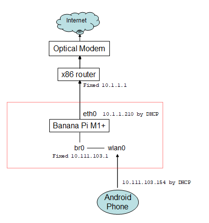
Now, my android phone can access the internet and the Banana Pi works as expected. However, when I checked the file /var/log/syslog of the x86 router, I found :
Jan 20 00:12:51 router86 kernel: [25688.378214] IPv4: martian source 104.17.115.27 from 10.111.103.154, on dev br0
Jan 20 00:12:51 router86 kernel: [25688.378253] ll header: 00000000: 00 e0 4c 68 12 86 02 d4 09 42 7c 37 08 00        ..Lh.....B|7..
Jan 20 00:12:51 router86 kernel: [25688.378422] IPv4: martian source 104.17.115.27 from 10.111.103.154, on dev br0
Jan 20 00:12:51 router86 kernel: [25688.378433] ll header: 00000000: 00 e0 4c 68 12 86 02 d4 09 42 7c 37 08 00        ..Lh.....B|7..
Jan 20 00:12:51 router86 kernel: [25688.379413] IPv4: martian source 104.17.115.27 from 10.111.103.154, on dev br0
Jan 20 00:12:51 router86 kernel: [25688.379426] ll header: 00000000: 00 e0 4c 68 12 86 02 d4 09 42 7c 37 08 00        ..Lh.....B|7..
Jan 20 00:12:51 router86 kernel: [25688.379573] IPv4: martian source 104.17.115.27 from 10.111.103.154, on dev br0
Jan 20 00:12:51 router86 kernel: [25688.379582] ll header: 00000000: 00 e0 4c 68 12 86 02 d4 09 42 7c 37 08 00        ..Lh.....B|7..
Jan 20 00:12:51 router86 kernel: [25688.380656] IPv4: martian source 104.17.115.27 from 10.111.103.154, on dev br0
Jan 20 00:12:51 router86 kernel: [25688.380668] ll header: 00000000: 00 e0 4c 68 12 86 02 d4 09 42 7c 37 08 00        ..Lh.....B|7..
Jan 20 00:12:51 router86 kernel: [25688.380817] IPv4: martian source 104.17.115.27 from 10.111.103.154, on dev br0
Jan 20 00:12:51 router86 kernel: [25688.380827] ll header: 00000000: 00 e0 4c 68 12 86 02 d4 09 42 7c 37 08 00        ..Lh.....B|7..
Jan 20 00:12:51 router86 kernel: [25688.382479] IPv4: martian source 104.17.115.27 from 10.111.103.154, on dev br0
Jan 20 00:12:51 router86 kernel: [25688.382489] ll header: 00000000: 00 e0 4c 68 12 86 02 d4 09 42 7c 37 08 00        ..Lh.....B|7..
Jan 20 00:12:51 router86 kernel: [25688.382693] IPv4: martian source 104.17.115.27 from 10.111.103.154, on dev br0
Jan 20 00:12:51 router86 kernel: [25688.382703] ll header: 00000000: 00 e0 4c 68 12 86 02 d4 09 42 7c 37 08 00        ..Lh.....B|7..
Jan 20 00:12:51 router86 kernel: [25688.382911] IPv4: martian source 104.17.115.27 from 10.111.103.154, on dev br0
Jan 20 00:12:51 router86 kernel: [25688.382920] ll header: 00000000: 00 e0 4c 68 12 86 02 d4 09 42 7c 37 08 00        ..Lh.....B|7..
Jan 20 00:12:51 router86 kernel: [25688.415770] IPv4: martian source 104.17.115.27 from 10.111.103.154, on dev br0
Jan 20 00:12:51 router86 kernel: [25688.415809] ll header: 00000000: 00 e0 4c 68 12 86 02 d4 09 42 7c 37 08 00        ..Lh.....B|7..
The internal IP of my phone (10.111.103.154) behind the Banana Pi leaked to the external x86 router !
How can I fix this ?
Thanks.
-
22 hours ago, Phillip Close said:
Ok I have done 3 version oh the kernel but sill no dvb support for the t230 dvb stick please tell me what to enable when using the tool in the document lol and my kernel seam to be 3.2 gig img lol
Please try this : https://github.com/igorpecovnik/lib
-
@tkaiser
The situation happened in Armbian_5.26.170215_Orangepipc2_Ubuntu_xenial_dev_4.10.0.
I upgrade my system by apt-get everyday, so I think my system is uptoday now. Here is the result I just tested. My PC2 was idle during the test :
root@orangepipc2:~# armbianmonitor -m     # <== using ondemand
Stop monitoring using [ctrl]-[c]
Time        CPU    load %cpu %sys %usr %nice %io %irq   CPU
01:10:15:  480MHz  0.10   3%   1%   1%   0%   0%   0% 23.6°C
01:10:20:  480MHz  0.09   3%   1%   1%   0%   0%   0% 23.8°C
01:10:25:  480MHz  0.08   3%   1%   1%   0%   0%   0% 23.5°C
01:10:30:  480MHz  0.08   3%   1%   1%   0%   0%   0% 23.9°C
01:10:35:  480MHz  0.07   3%   1%   1%   0%   0%   0% 24.2°C
01:10:40:  480MHz  0.06   3%   1%   1%   0%   0%   0% 26.2°C
01:10:45:  480MHz  0.06   3%   1%   1%   0%   0%   0% 24.9°C
01:10:50:  480MHz  0.05   3%   1%   1%   0%   0%   0% 24.2°C
01:10:55:  480MHz  0.05   3%   1%   1%   0%   0%   0% 24.8°C
01:11:00:  480MHz  0.05   3%   1%   1%   0%   0%   0% 23.6°C^C
root@orangepipc2:~# echo schedutil > /sys/devices/system/cpu/cpufreq/policy0/scaling_governor
root@orangepipc2:~# armbianmonitor -m
Stop monitoring using [ctrl]-[c]
Time        CPU    load %cpu %sys %usr %nice %io %irq   CPU
01:11:28: 1296MHz  0.03   2%   1%   1%   0%   0%   0% 28.0°C
01:11:33: 1296MHz  0.02   2%   1%   1%   0%   0%   0% 29.0°C
01:11:38: 1296MHz  0.02   2%   1%   1%   0%   0%   0% 29.0°C
01:11:43: 1296MHz  0.02   2%   1%   0%   0%   0%   0% 29.0°C
01:11:48: 1296MHz  0.02   2%   1%   0%   0%   0%   0% 29.1°C
01:11:53:  480MHz  0.02   2%   1%   0%   0%   0%   0% 24.8°C
01:11:58: 1296MHz  0.02   2%   1%   0%   0%   0%   0% 29.1°C
01:12:03: 1296MHz  0.01   2%   1%   0%   0%   0%   0% 30.0°C
01:12:08: 1296MHz  0.01   2%   1%   0%   0%   0%   0% 30.5°C
01:12:13: 1296MHz  0.01   2%   1%   0%   0%   0%   0% 30.5°C
01:12:18: 1296MHz  0.01   2%   0%   0%   0%   0%   0% 28.9°C
01:12:23: 1296MHz  0.01   2%   0%   0%   0%   0%   0% 31.8°C
01:12:28: 1296MHz  0.01   2%   0%   0%   0%   0%   0% 31.3°C
01:12:33: 1296MHz  0.01   2%   0%   0%   0%   0%   0% 31.6°C
01:12:38: 1296MHz  0.01   2%   0%   0%   0%   0%   0% 31.0°C
01:12:43: 1296MHz  0.01   2%   0%   0%   0%   0%   0% 32.3°C
01:12:49: 1296MHz  0.00   2%   0%   0%   0%   0%   0% 30.6°C
01:12:54: 1296MHz  0.00   2%   0%   0%   0%   0%   0% 32.2°C^C
root@orangepipc2:~#
Nanopi-M4 mainline kernel nighty : MAC address changes on every reboot
in Rockchip
Posted
Yes, I understand. I just want to report the bug.