

Frank Wu
-
Posts
7 -
Joined
-
Last visited
Content Type
Forums
Store
Crowdfunding
Applications
Events
Raffles
Community Map
Posts posted by Frank Wu
-
-
Here is the v67 chromium deb from Debian's archive server.
That is currently latest version can be worked from Debian's pre-build package...v68, even just released v69 all cannot execute properly...
-
8 hours ago, Tido said:
No matter how thick your cable is, the connector is designed for 1,8A (Micro USB) and a certain amount of cycle's (plug unplug) – as a technician you should make your point towards the Designer/Marketing how to offer at least an easy option to improve power situation for "tinkerer's".y such an option has not been considered ?
Hi,
We've noticed this concerns at the beginning.
As a matter of fact, believe that we are more worried about any safety design than our guests if out of the power current spec.
So that connector on the Tinker Board & Tinker Board S. We all requires our vendor need to qualified the pressure & safety stress test with 5V/3A.
They can all be relieved to used and can withstand 5v/3a.(as I knew, the 1.8A is more like a reference standard, so also have lots connectors are required more than 1.8A.)
8 hours ago, Tido said:Is there an engineering point of view, why such an option has not been considered ?
Since we have no intention of changing too much layout design and let it can have the highest possibility to fit RPI form-factor's 3rd party case, components, etc.
BTW glad to know you like our colorful design on GPIO, that is my favorite part too.
And we would be noted, also survey the DC jack design for If there are any new products in the future.
-
2 hours ago, chwe said:
the best choice lacks of some information. Thickness of cables (e.g. AWG XX).
Here is this power supply's spec sheet: https://www.asus.com/Single-Board-Computer/Tinker-Power-Supply/specifications/
- DC 5.0V / 3.0A 15W
- 18AWG 150CM + Power Switch
- SCP, OVP, OCP, OTP, etc Power Protection.
- UL / CB / CE
- US DoE Level VI / EU CoC Tier 2
- LPS, etc lots of safety cert mark.
2 hours ago, chwe said:Did you check how it reacts to spikes (e.g. voltage drop when the board decides that it needs fastly 'more juice'?). Average voltage drop between low current and high current usage?
No, currently I don't think I have kind of this data, but I can provide the result from my simple test for refer:
- low current: avg. 4.99v- high current: avg. 4.87v (CPU 4 core, 400%.)
-
Hi~
About how we suggest to prevent the voltage drop.
Not much but can reference,
- 5V and full power as the spec. (e.g. some supply said 5v/2a (10W), but actually, when you asked v2a, you would see it may only provide 4.8v/2a)
- We would suggest using 3A (15W) to prepare for the high loadings.
- The cable with 20~18 AWG for large current power usage.
-
We also provide the best and official choice, the Tinker Power Supply.
And you can check what is the current voltage in the system.
Take a look with this node, "/sys/bus/iio/devices/iio:device0/in_voltage2_raw".
If it had been there and assumed the function was normal. You can refer below sample code (python) to get voltage.
DETECT_VOLTAGE = 4.65 #4.65
ADC_IN2_RAW_PATH = '/sys/bus/iio/devices/iio:device0/in_voltage2_raw'

with open(ADC_IN2_RAW_PATH) as in_voltage2_raw:
  val2_raw = int(in_voltage2_raw.readline())
  val_input = float(val2_raw / ((82.0/302.0) * 1023.0 / 1.8)) + 0.1
  print('Voltage: ' + str(val_input))

  if val_input < DETECT_VOLTAGE:
    print('-- Low Voltage --')
    print('The system may turn off due to low power input (input voltage below 4.65V), when this happens, please disconnect high power consuming peripherals or change to a qualified power supply.')
// In TinkerOS, you can find a service at "lib/systemd/system/voltage-detect.service" and similar codes "etc/init.d/voltage-detect.py".
Thanks.
-
11 hours ago, chwe said:
it can (ore parts can be compiled as module) but it didn't work properly..
or you write the corresponding device tree for the MiQi too so that both can benefit from it.

I'm not sure if ASUS developed it.. Cause this one here: https://github.com/joerg65/gpiomem_tinkerboard looks very similar and he uploaded it on 27 Sep 2017, Asus did it a few days later 12 Oct 2017. Would be a bit nasty if they stole his code and removed him as an author (there are some differences and I don't want to start a shitstorm here, but we might clarify it first do it right.
") ).
4
).
4Hi @chwe,
Nice to meet you.
I'm one of Tinker Board team member and also is the one of in charge of the community.
I remember for this case.
We have required our RD team need to take a kindly asking with joerg65 to get the confirm. (And we got the approved to add it)
Even as we know, it's an open source and public codes, we can directly use them by following GPL license.
But we also would make a confirm with them. Because we want to let everyone understand, we are very serious about all contribution in the open source world.So, please don't worried about this.
Kindly let us have few days to double check it more internally.
And discuss with RD team, to know how can we do for let it better, e.g. add missed commit log or other ways to prove is joerg65's contribution.BR,
Thanks.
-
17 hours ago, freak said:
The wrong side of the usb cable? I'm inline between the tinker and power supply. That's how you do it. Here it is with a keyboard, mouse dongle and usb speakers plugged into it.
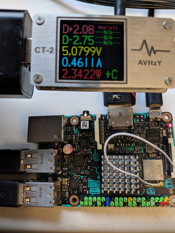
Hello @freak,
How about try below method to get the actually current system Voltage?

that would more close with the true voltage. (But cannot get the current)
Also if measuring voltage between PSU and Cable, it would miss the Cable’s effect.
(if cable also cause the voltage drop…)

HW acceleration through x server not working
in Tinkerboard
Posted
How about replace glxgears to es2gears?
Since there are only software render at OpenGL, if want to use GPU need to use OpenGL ES.