Search the Community
Showing results for 'waveshare'.
-
Hello, I have a new LCD which I believe is an ili4988 (although the vendor says ili9486 and st7796) https://www.aliexpress.us/item/3256803856059047.html I have read somewhere, that I can use an ili9341 spi driver, only by changing the resolution and changing the initialization script. I looked in the waveshare website and github, they don't have anything for the ili9488 Then, I found some arduino code in http://www.lcdwiki.com/3.5inch_SPI_Module_ILI9488_SKU%3AMSP3520 (look for the "3.5 inch SPI Module Package(ILI9488)" link, then find the LCDWIKI_SPI.cpp The initialization sequence is in line 1697: I am currently trying to convert it to a DTS-format init string, so that it fits my ili9341-fb.dts, which I made earlier this year: I am unsure how to start the init line, can someone help me? Then, when I have that init string confirmed, I can use: https://github.com/notro/panel-mipi-dbi/wiki https://blog.csdn.net/CNflysky/article/details/125171176 To switch to the mipi-dbi driver, which would get me DRM (instead of FB)
-
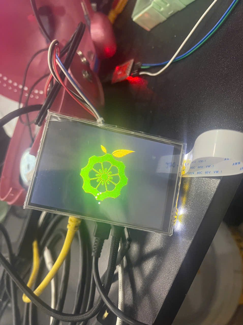
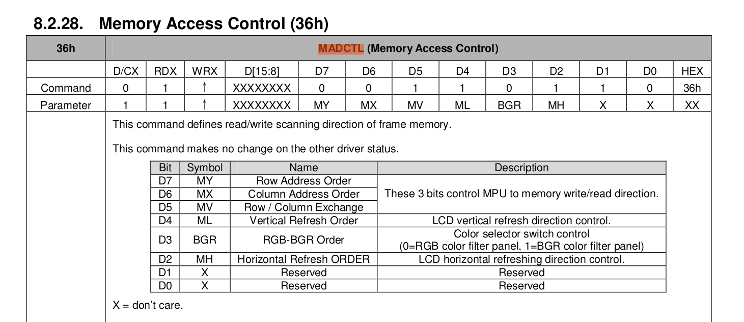
Hi everyone, I have wrong color in screen MPI3501 , when i test to output buffer to color red,green, blue, it seem like Red. —> blue Green —> red Blue. —> green Here is how i test (i need to stop lightdm service before this) (when boot the image should be orange not green) I am using display MPI3501 http://www.lcdwiki.com/3.5inch_RPi_Display which i heard that is a clone of waveshare 3,5 inch https://www.waveshare.com/3.5inch-RPi-LCD-C.htm I'm using Debian Bookworm. I know that it not the same as Armbian, but the config kinda the same. About driver for ili9486, here is the info To use this screen i create overlay-user. and and ili9486.dts. Here is the content of it and I add this overlay to /boot/orangepiEnv.txt Note that i think the field "bgr" and "init" not working, i try to change it to make bgr from 0x00 to 0x01, or send init different at 0x10000036 but nothing change. Also note that, i also try to cat raw data from /dev/fb0 and using ffmpeg --> It is true color Also here is the dmesg log Is anyone here familiar with this problem, or ever try to change bgr field of this ili9486 ? Best Regard !!


-

Orangepi Zero 2W wrong color display on MPI3501
robertoj replied to Minh Tiến Nguyễn's topic in Allwinner sunxi
I am glad you could do it with the orange pi zero 2w, because I also want to use a very small arm board I am having trouble with the red ili9488 red LCD's touch function, and if I keep having no results, I will replace with the waveshare LCD model (I wanted to have 4-inch LCD ) What armbian and linux version did you use? If you go to the latest linux, you may need to modify the DTS a little bit (modifications are in my ili9488 thread). Warning: I use a different driver (parameter "compatible") for DRM graphics, and different drivers might need different DTS lines. Always use a different microSD for experiments, so you don't mess with your working setup Does the orange pi zero 2w just need male pin headers on the 40-pin connector, and then plug the LCD on top? -

OrangePi Zero LTS ili9341 TFT LCD (and later OrangePi Zero 3)
Minh Tiến Nguyễn replied to robertoj's topic in Allwinner sunxi
Hello @robertoj I think i have the same problem with @RimYT above about wrong color with ili9486, i'm using screen MPI3501 which is clone screen of waveshare tft35 I apply the same device tree and guide in https://github.com/dev-null2019/orangepizero2w35tft. The screen work but i wrong color, it seem revered Red. —> blue Green —> red Blue. —> green I also write detail in here I know my problem not totally related to your topic, but can you suggest me what i should to check more -
I am also available for testing new images on Orange Pi Zero 3, while I am new to this SBC I am happy to learn. Today I have installed "Armbian_community_25.8.0-trunk.38_Orangepizero3_bookworm_current_6.12.23_minimal.img" to use for NTP server purposes. I have successfully enabled uart5 by using "overlays=uart5" and seeing GPS data with "gpsmon /dev/ttyS1". However, I also want to use PPS signal coming from my Waveshare L76K module, and the pps device does not seem to be created. I have used the following dts, from this forum: /dts-v1/; /plugin/; / { compatible = "allwinner,sun50i-h616"; fragment@0 { target = <&pio>; __overlay__ { pps_pins: pps_pins { pins = "PC7"; function = "gpio_in"; }; }; }; fragment@1 { target-path = "/"; __overlay__ { pps@0 { compatible = "pps-gpio"; pinctrl-names = "default"; /* pinctrl-0 = <&pps_pins>; */ gpios = <&pio 2 7 0>; /* PC7 */ status = "okay"; }; }; }; }; Then I did "armbian-add-overlay sun50i-h616-pps-gpio.dts" followed by a reboot. Then I do not see any PPS device. Am I missing something else?
-
robertoj, Thanks for your answer! I have raspberry pi LCD 3.5 inch https://www.waveshare.com/wiki/3.5inch_RPi_LCD_(A)Yes, I'm using Linux 6.12.23. I did like you said. Used latest DTS (April 3). Display is still white My armbianEnv: verbosity=1 bootlogo=false console=both disp_mode=1920x1080p60 rootdev=UUID=6b7fd251-3dcf-4583-9378-223fcd52e8db rootfstype=ext4 user_overlays=ili9486-35 usbstoragequirks=0x2537:0x1066:u,0x2537:0x1068:u My dmesg: [ 1.524875] sun4i-drm display-engine: bound 1100000.mixer (ops 0xffff80008121b478) [ 1.525068] sun4i-drm display-engine: bound 6510000.tcon-top (ops 0xffff800081220248) [ 1.525400] sun4i-drm display-engine: bound 6515000.lcd-controller (ops 0xffff800081218098) [ 1.526527] sun4i-drm display-engine: bound 6000000.hdmi (ops 0xffff80008121a540) [ 1.527009] [drm] Initialized sun4i-drm 1.0.0 for display-engine on minor 0 [ 1.710803] sun4i-drm display-engine: [drm] fb0: sun4i-drmdrmfb frame buffer device [ 1.729347] sun6i-spi 5010000.spi: Error applying setting, reverse things back [ 1.729724] sun6i-spi 5011000.spi: Failed to request TX DMA channel [ 1.729735] sun6i-spi 5011000.spi: Failed to request RX DMA channel [ 1.729803] ili9486@0 enforce active low on GPIO handle [ 1.729841] sun6i-spi 5011000.spi: cannot register SPI host [ 1.736253] sun6i-spi 5010000.spi: Error applying setting, reverse things back [ 1.736622] sun6i-spi 5011000.spi: Failed to request TX DMA channel [ 1.736634] sun6i-spi 5011000.spi: Failed to request RX DMA channel [ 1.736686] ili9486@0 enforce active low on GPIO handle [ 1.736721] sun6i-spi 5011000.spi: cannot register SPI host [ 1.744337] spi-nor spi0.0: supply vdd not found, using dummy regulator [ 1.773831] sun6i-spi 5011000.spi: Failed to request TX DMA channel [ 1.773862] sun6i-spi 5011000.spi: Failed to request RX DMA channel [ 1.773934] ili9486@0 enforce active low on GPIO handle [ 5.476562] systemd[1]: Starting modprobe@drm.service - Load Kernel Module drm... [ 5.545342] systemd[1]: modprobe@drm.service: Deactivated successfully. [ 5.546346] systemd[1]: Finished modprobe@drm.service - Load Kernel Module drm. [ 6.742260] ads7846 spi1.1: supply vcc not found, using dummy regulator [ 6.742814] ads7846 spi1.1: touchscreen, irq 73 [ 6.743326] input: ADS7846 Touchscreen as /devices/platform/soc/5011000.spi/spi_master/spi1/spi1.1/input/input6 [ 6.760484] [drm] Initialized ili9486 1.0.0 for spi1.0 on minor 1 [ 6.762759] ili9486 spi1.0: [drm] fb1: ili9486drmfb frame buffer device [ 6.913940] [drm] Initialized panfrost 1.2.0 for 1800000.gpu on minor 2
-
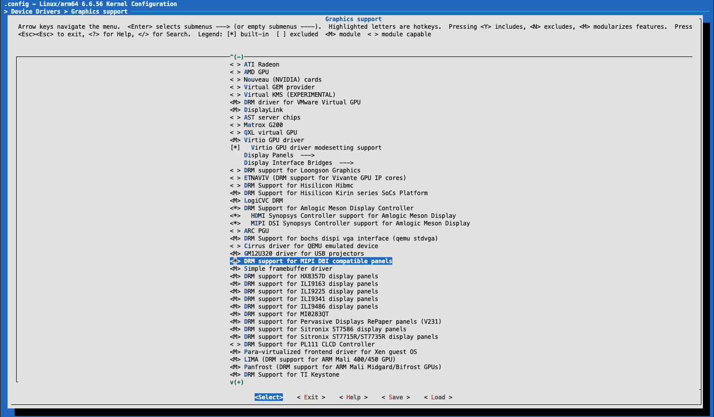
Hello, Thank you for the great effort of Armbian having community support of this board. I have a Waveshare 4inch DSI LCD with touch that I want to use it with Radxa Zero 2 Pro. They have a device tree overlay provided for Raspberry Pi and drivers for different kernels for RPi And I found a kernel patch that seem to enable DSI here. ********************************************************************** I am using the latest build of Armbian for radxa-zero2 and it's Linux radxa-zero2 6.6.53-current-meson64 When I find /lib/modules/$(uname -r) -type f -name '*dsi*' It shows /lib/modules/6.6.53-current-meson64/kernel/drivers/gpu/drm/hisilicon/kirin/dw_drm_dsi.ko /lib/modules/6.6.53-current-meson64/kernel/drivers/gpu/drm/panel/panel-dsi-cm.ko /lib/modules/6.6.53-current-meson64/kernel/drivers/gpu/drm/bridge/nwl-dsi.ko /lib/modules/6.6.53-current-meson64/kernel/drivers/gpu/drm/bridge/cadence/cdns-dsi.ko /lib/modules/6.6.53-current-meson64/kernel/drivers/gpu/drm/bridge/ti-sn65dsi83.ko /lib/modules/6.6.53-current-meson64/kernel/drivers/mtd/nand/raw/nandsim.ko When I zcat /proc/config.gz | grep DSI It shows CONFIG_MTD_NAND_NANDSIM=m CONFIG_DRM_MIPI_DSI=y CONFIG_DRM_PANEL_DSI_CM=m CONFIG_DRM_NWL_MIPI_DSI=m # CONFIG_DRM_SAMSUNG_DSIM is not set CONFIG_DRM_TI_SN65DSI83=m # CONFIG_DRM_TI_SN65DSI86 is not set CONFIG_DRM_CDNS_DSI=m CONFIG_DRM_CDNS_DSI_J721E=y CONFIG_DRM_DW_MIPI_DSI=y CONFIG_DRM_MESON_DW_MIPI_DSI=y Questions AFAIK, that means the DSI interface is enabled and what I need to do is to compile a .dtbo device tree overlay based on Waveshare's and then load it into the system? And I assume the LCD needs some kind of 'driver' but Waveshare only provides some .ko and .dtso files in their GitHub repo. They have as recent as kernel 6.6.20, can I use that driver and how? As for compiling a device tree source DTS into a Device Tree Blog DTB, do I use the traditional way of dtc -I dts -O dtb -o output_file.dtb input_file.dts or using armbian-add-overlay (however the documentation says DT overlays are a Work-in-Progress (WIP) feature, present only in certain images.) Is there a way that I can verify if the DSI interface is functioning at all before I move on to the driver and overlay issue? That way I won't be working with too many uncertainties. I measured some of the pins on the DSI port on the monitor side and they seem to be 'functioning` (as there are pins with voltages and a 3.3v, plus there's LED on the monitor that is blinking - I didn't go as far as checking if the 3.3v pin is in accordance of the Radxa Zero 2 Pro side for the DSI port, nor I did try to logic analyse other pins) ********************************************************************** I have tried to compile Armbian and choose ` > Device Drivers > Graphics support > DRM support for MIPI DBI compatible panels > *

-
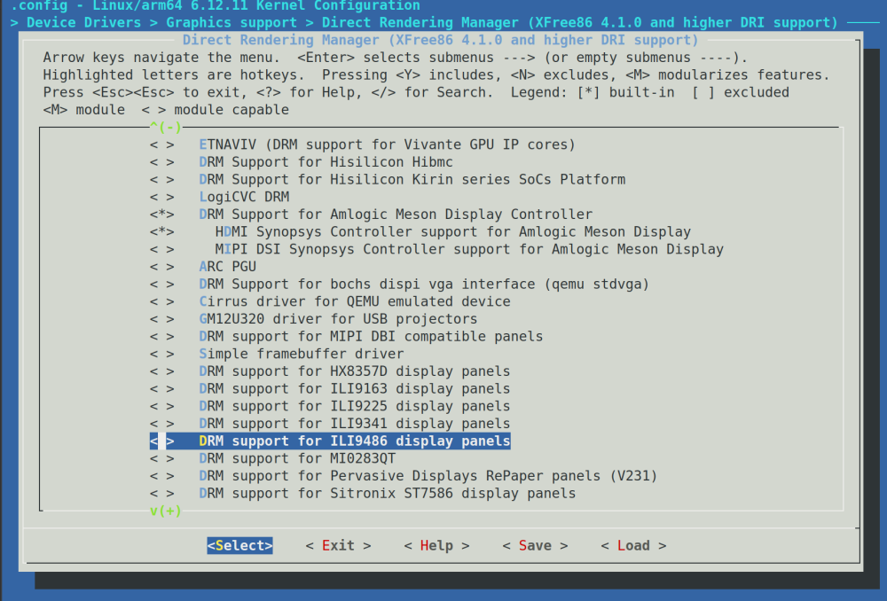
i dont know if this is new, but i see a ili9486 driver in the kernel config, which is unselected by default. Warning.... I just looked at some of the code in the linux mailing list discussion, and it looks like it is made specifically for 2 raspberry LCD hats * PISCREEN 3.5" 320x480 TFT (Ozzmaker 3.5") * RPILCD 3.5" 320x480 TFT (Waveshare 3.5") Which have a SPI->parallel chip on the circuitboard https://patchwork.kernel.org/project/dri-devel/patch/eb5672abbdb89d7018793c76d7193bfb78a2ea88.1580059987.git.kamlesh.gurudasani@gmail.com/ WDR_s: are you still having good experience with the ili9341 driver for the ili9486 LCD?
-

Driving the ili9488 LCD (4.0 inch cheap chinese clone)
le51 replied to robertoj's topic in Allwinner sunxi
This is from panel-mipi-dbi-spi.txt command 0xE0 0x00 0x03 0x09 0x08 0x16 0x0A 0x3F 0x78 0x4C 0x09 0x0A 0x08 0x16 0x1A 0x0F command 0xE1 0x00 0x16 0x19 0x03 0x0F 0x05 0x32 0x45 0x46 0x04 0x0E 0x0D 0x35 0x37 0x0F This is from LCDWIKI_SPI.cpp for ili9488: 0xE0, 15, 0x00, 0x07, 0x10, 0x09, 0x17, 0x0B, 0x41, 0x89, 0x4B, 0x0A, 0x0C, 0x0E, 0x18, 0x1B, 0x0F, 0xE1, 15, 0x00, 0x17, 0x1A, 0x04, 0x0E, 0x06, 0x2F, 0x45, 0x43, 0x02, 0x0A, 0x09, 0x32, 0x36, 0x0F, They are other commands that differs slightly. I've found other sources for the init sequence which seems all to be close to panel-mipi-dbi-spi.txt : * Juj fbcp lib: https://github.com/juj/fbcp-ili9341/blob/master/ili9488.cpp#L28 * Bodmer eTFT_SPI lib for microcontrollers : https://github.com/Bodmer/TFT_eSPI/blob/master/TFT_Drivers/ILI9488_Init.h#L11 * Jarret Bucket Adafruit GLX lib : https://github.com/jaretburkett/ILI9488/blob/master/ILI9488.cpp#L378 * this one is for STM32 : https://github.com/RobertoBenjami/stm32_graphics_display_drivers/blob/master/Drivers/lcd/ili9488/ili9488.c#L219 In the same manner, we can found init sequences for other chips in these libraries, eg ili9486. There's already a driver in the kernel source : https://web.git.kernel.org/pub/scm/linux/kernel/git/stable/linux.git/tree/drivers/gpu/drm/tiny/ili9486.c?h=linux-6.12.y but it is specific to Waveshare 35a or PiScreen displays (these with 4 kind of shift register ICs onboard). So for now, while waiting for a new ili9488 display arrives home, I'm digging further around the right init sequence for ili9486. -
Forgive me. I apparently don't test thoroughly enough. Now: rock@rockpi-4cplus:~$ cat /boot/armbianEnv.txt verbosity=1 bootlogo=true console=display overlay_prefix=rockchip rootdev=UUID=d0636019-ca11-404a-9874-04e6cbfedf37 rootfstype=ext4 usbstoragequirks=0x2537:0x1066:u,0x2537:0x1068:u rock@rockpi-4cplus:~$ sudo mkimage -C none -A arm -T script -d /boot/boot.cmd /boot/boot.scr Image Name: Created: Sat Mar 8 18:21:32 2025 Image Type: ARM Linux Script (uncompressed) Data Size: 3843 Bytes = 3.75 KiB = 0.00 MiB Load Address: 00000000 Entry Point: 00000000 Contents: Image 0: 3835 Bytes = 3.75 KiB = 0.00 MiB rock@rockpi-4cplus:~$ sudo reboot Broadcast message from root@rockpi-4cplus on pts/1 (Sat 2025-03-08 18:22:02 UTC): The system will reboot now! rock@rockpi-4cplus:~$ Remote side unexpectedly closed network connection Even so, I can see my communication with Waveshare SIM7020E NB-IoT HAT are interrupted by console login request. How do I fulfill the disable ttyS2 console? rock@rockpi-4cplus:~$ sudo picocom /dev/ttyS2 picocom v3.1 Terminal ready *** local echo: yes *** *** baud: 115200 *** baud: 115200 *** AT AT OK rockpi-4cplus login:
-
Set fan max speed to kick in at 65C. This keeps the unit roughly at 70C or lower, when pusing all cores for an extended period of time. Checklist: [ ] My code follows the style guidelines of this project [ ] I have performed a self-review of my own code [ ] I have commented my code, particularly in hard-to-understand areas [ ] I have made corresponding changes to the documentation [X] My changes generate no new warnings [ ] Any dependent changes have been merged and published in downstream modules View the full article
-
 v2: arch: arm64: dts: amlogic: meson-g12b-waveshare-cm4-io-base-b Fan, RTC and USB support RTC requires rtc pcf85063 driver Fan requires hwmon emc2305 driver (new addition) hwmon: emc2305: fixups for driver The driver had a number of issues, checkpatch warnings/errors, and other limitations, so fix these up to make it usable. Additional: hwmon: emc2305: Change OF properties pwm-min & pwm-max to u8 hwmon: emc2305: Add calls to initialize cooling maps How was it tested? Built a new image with the following changes and booted to make sure it works as it should. Inactive: == Waveshare CM4-IO-BASE-B with BPI-CM4 Module (6.1.57-current-meson64) CPU usage: 0 Processors: Cortex-A53 @ 2016MHz 51°C, Cortex-A73 @ 2400MHz 53°C Cur freq: 1000MHz 2400MHz Fan: 0 RPM (0) <-- FAN INACTIVE Online: 0-5 Governor: ondemand Memory: 3.7G 331M Entropy: 256 Uptime: 14:12:26 up 18 min, 4 users, load average: 0.01, 0.24, 0.31 Active: == Waveshare CM4-IO-BASE-B with BPI-CM4 Module (6.1.57-current-meson64) CPU usage: 90 Processors: Cortex-A53 @ 2016MHz 82°C, Cortex-A73 @ 2400MHz 82°C Cur freq: 2016MHz 2400MHz Fan: 3368 RPM (255) <-- FAN ACTIVE Online: 0-5 Governor: ondemand Memory: 3.7G 430M Entropy: 256 Uptime: 14:19:09 up 25 min, 4 users, load average: 1.76, 1.06, 0.64 NOTE: The temps are not as they should be as they sent me a 12V instead of a 5V fan. I decided to keep the 12V to do the testing with, as I wait for the 5V to arrive. The difference between them shouldn't change the basic functionality, only the quality of the cooling. Checklist: [ ] My code follows the style guidelines of this project [ ] I have performed a self-review of my own code [ ] I have commented my code, particularly in hard-to-understand areas [ ] I have made corresponding changes to the documentation [X] My changes generate no new warnings [ ] Any dependent changes have been merged and published in downstream modules View the full article
 -
meson64/edge 6.5.y: move meson-g12b-waveshare-cm4-io-base-b.dts out of null patch, avoid patching Makefile meson64/edge 6.5.y: move meson-g12b-waveshare-cm4-io-base-b.dts out of null patch, avoid patching Makefile View the full article
-
Recently I tried to connect CAN bus adapter to my Orange Pi 3 LTS board and it happened that there is not so much information about it, it is outdated or related to other boards. So, after I spent a few days in trials and errors below is my recipe. 1. Connect a CAN interface board. Orange Pi pins are not 5V tolerant, so I decided to use a dedicated 2-channel board from Waveshare: https://www.waveshare.com/2-ch-can-hat.htm (only one channel for the start). You can modify a cheap board from AliExpress though; there are instructions in the Internet. I used the PL10 pin of Orange Pi 3 LTS board as INT pin. Actually first I tried to use the PD21 pin but it seems that this pin cannot generate interrupts for some reason and it took a few days to find the solution. Also note that in the overlay this pin bank is set as 0 (as if it would set for the PA10 pin). I have no idea why it should be set this way, maybe someone would explain. 2. Activate the SPI interface in the device tree (it is disabled by default). So, first decompile the device tree: mentioning that you are using the 3LTS board, you need the /boot/dtb/allwinner/sun50i-h6-orangepi-3-lts.dtb file. Decompile it with the following command: dtc -I dtb -O dts -o sun50i-h6-orangepi-3-lts.dts sun50i-h6-orangepi-3-lts.dtb . Edit the dts file a little: in the resulting text file sun8i-h3-orangepi-pc.dts find section named like spi@5011000 and change the status field value from “disabled” to “okay”. Then compile the dts file back to dtb: dtc -I dts -O dtb -o sun50i-h6-orangepi-3-lts.dtb sun50i-h6-orangepi-3-lts.dts . 3. Add an overlay file for the MCP25251 interface. Compile the attached overlay file sun50i-h6-spi-mcp2515.dts: dtc –I dts –O dtb –o sun50i-h6-spi-mcp2515.dtbo sun50i-h6- spi-mcp2515.dts . Copy the resulted .dtbo file into the /boot/overlay-user folder and add into the /boot/orangepiEnv.txt string user_overlays=sun50i-h6-spi-mcp2515 . 4. Install CAN tools: sudo apt-get install can-utils . 5. Restart your board. 6. Make sure that the CAN interface is initialized; run the following command: dmesg | grep spi||mcp . You will see a line like this: mcp251x spi1.0 can0: MCP2515 successfully initialized. 7. Activate the CAN bus; run the following command: ip link set can0 up type can bitrate 500000 . 8. Make sure that the CAN bus is active; run the following command: ip –det link show can0 . You should see that the bus has UP state now. Hope this helps and sorry if I missed something. sun50i-h6-spi-mcp2515.dts
-
context ------------ Hardware: BPI CM4 on BPI CM4IO board OS: Armbian 24.11.1 Bookworm Minimal Build: https://dl.armbian.com/bananapicm4io/Bookworm_current_minimal problem ------------ How do i enable i2c2 so i can be able to use the following pins on the BPI CM4IO board for i2c pin 82 (GPIOX_17): (MUX UNCLAIMED) (GPIO UNCLAIMED) pin 83 (GPIOX_18): (MUX UNCLAIMED) periphs-banks:595 Previously on the ubuntu build all i had to do is add the following line to `/boot/env.txt` , `overlays="12c2"`, as stated in this doc https://wiki.banana-pi.org/Getting_Started_with_CM4#DTB_overlay 2. Update the overlays env in vfat /boot/env.txt to enable what you want. # Device Tree Overlays # uart1 -- Enable UART1 (uart_A, GPIO Header PIN8 & PIN10) # pwm_c -- Enable PWM_C (GPIO Header PIN7) # i2c2 -- Enable i2c2 (GPIO Header PIN3 & PIN5) # spi0 -- Enable SPI0 (GPIO Header PIN19 & PIN21 & PIN23 & PIN24) overlays="i2c2 spi0 uart1" but on the `Armbian 24.11.1 Bookworm Minimal Build` i cant find this overlay pi@bananapicm4io:~$ sudo ls /boot/dtb-6.6.61-current-meson64/amlogic/overlay/ README.meson-overlays meson-g12a-radxa-zero-pwmao-a-on-gpioao-11.dtbo meson-i2cA.dtbo meson-fixup.scr meson-g12a-radxa-zero-spi-spidev.dtbo meson-i2cB.dtbo meson-g12-gxl-cma-pool-896MB.dtbo meson-g12a-radxa-zero-uart-ao-a-on-gpioao-0-gpioao-1.dtbo meson-sm1-bananapi-m5-rtl8822cs.dtbo meson-g12-pwm-gpiox-5-fan.dtbo meson-g12a-radxa-zero-uart-ao-b-on-gpioao-2-gpioao-3.dtbo meson-sm1-bananapi-uartA.dtbo meson-g12a-radxa-zero-gpio-10-led.dtbo meson-g12a-radxa-zero-uart-ao-b-on-gpioao-8-gpioao-9.dtbo meson-sm1-bananapi-uartAO_B.dtbo meson-g12a-radxa-zero-gpio-8-led.dtbo meson-g12a-radxa-zero-uart-ee-c.dtbo meson-sm1-bananapi-uartA_cts_rts.dtbo meson-g12a-radxa-zero-i2c-ao-m0-gpioao-2-gpioao-3.dtbo meson-g12b-bananapi-cm4-pwm-gpioh-5-fan.dtbo meson-uartA.dtbo meson-g12a-radxa-zero-i2c-ee-m1-gpioh-6-gpioh-7.dtbo meson-g12b-bananapi-cm4-wifi-freq-200mhz.dtbo meson-uartC.dtbo meson-g12a-radxa-zero-i2c-ee-m1-gpiox-10-gpiox-11.dtbo meson-g12b-bananapi-m2s-rtl8822cs.dtbo meson-w1-gpio.dtbo meson-g12a-radxa-zero-i2c-ee-m3-gpioa-14-gpioa-15.dtbo meson-g12b-odroid-n2-spi.dtbo meson-w1AB-gpio.dtbo meson-g12a-radxa-zero-pwm-c-on-gpiox-8.dtbo meson-g12b-waveshare-cm4-io-base-usb.dtbo pi@bananapicm4io:~$ cat /boot/armbianEnv.txt verbosity=1 console=both overlay_prefix=meson fdtfile=amlogic/meson-g12b-bananapi-cm4-cm4io.dtb rootdev=UUID=e4b40e17-5d66-4b52-a45e-4a8c6cdee335 rootfstype=ext4 fdt_overlays= overlays=i2c2 usbstoragequirks=0x2537:0x1066:u,0x2537:0x1068:u pi@bananapicm4io:~$ i2cdetect output on Armbian (on ubuntu image i get a reading on i2cdetect -y 1 but not on armbian) pi@bananapicm4io:~$ sudo i2cdetect -l i2c-0 i2c Meson I2C adapter I2C adapter i2c-1 i2c Meson I2C adapter I2C adapter i2c-2 i2c DesignWare HDMI I2C adapter pi@bananapicm4io:~$ sudo i2cdetect -y 0 0 1 2 3 4 5 6 7 8 9 a b c d e f 00: -- -- -- -- -- -- -- -- 10: -- -- -- -- -- -- -- -- -- -- -- -- -- -- -- -- 20: -- -- -- -- -- -- -- -- -- -- -- -- -- -- -- -- 30: -- -- -- -- -- -- -- -- -- -- -- -- -- -- -- -- 40: -- -- -- -- -- -- -- -- -- -- -- -- -- -- -- -- 50: -- -- -- -- -- -- -- -- -- -- -- -- -- -- -- -- 60: -- -- -- -- -- -- -- -- -- -- -- -- -- -- -- -- 70: -- -- -- -- -- -- -- -- pi@bananapicm4io:~$ sudo i2cdetect -y 1 0 1 2 3 4 5 6 7 8 9 a b c d e f 00: -- -- -- -- -- -- -- -- 10: -- -- -- -- -- -- -- -- -- -- -- -- -- -- -- -- 20: -- -- -- -- -- -- -- -- -- -- -- -- -- -- -- -- 30: -- -- -- -- -- -- -- -- -- -- -- -- -- -- -- -- 40: -- -- -- -- -- -- -- -- -- -- -- -- -- -- -- -- 50: -- -- -- -- -- -- -- -- -- -- -- -- -- -- -- -- 60: -- -- -- -- -- -- -- -- -- -- -- -- -- -- -- -- 70: -- -- -- -- -- -- -- -- pi@bananapicm4io:~$
-
Hello Did anyone have success with connecting an ili9486 to an orangepi zero 3 or another SBC? I read that starting with linux 5.4, we need to change the reset pin polarity to 1, as show in https://github.com/swkim01/waveshare-dtoverlays/issues/24 I just got this LCD https://www.aliexpress.us/item/3256803856059047.html It is the bigger borther of the ili9341 which I already have working according to: https://forum.armbian.com/topic/44191-orangepi-zero-lts-ili9341-tft-lcd-and-later-orangepi-zero-3/#comment-204672 The interesting thing is: when I use the ili9341 dtbo with the ili9486, I see a fraction of the X11 desktop, in the left 15% of the LCD screen... so at least I know that the connections and lowest level protocol is working. However, when I try changing the compatible to ilitek,ili9486, with all the settings the same (except for rotation->rotate), I stay with a white screen. actually, some other Aliexpress buyer says that my LCD is ili9488… so everyone needs to check their actual lcd controller. I need to recompile Armbian tomorrow It appears that ili9488 is a clone of st7796s, which has this example DTS https://github.com/Sergey1560/fb_st7796s/blob/master/dts/sun50i-h6-st7796s.dts It also appears that having the correct init bytes is critical. Here's another reference: https://forum.allaboutcircuits.com/threads/configuration-of-lcd-with-linux.145849/
-
I’m trying to use a 3.5 LCD (waveshare clone) with ILI9486 + XPT2046 with my orange pi zero. My display is like this. I installed both Debian_buster_next_4.19.59 and Ubuntu_bionic_next_4.19.57 and I followed many guides in here with no success. I edited armbianEnv.txt and added these: overlays=spi-spidev spi-add-cs1 param_spidev_spi_bus=1 param_spidev_spi_cs=1 After that I ran this sudo modprobe fbtft_device custom name=fb_ili9486 gpios=dc:18,reset:2 speed=16000000 busnum=1 rotate=90 and didn’t get any error. I figured that the reset & DC pins on orange pi zero are pin22(GPIO2) and pin18(GPIO18) but I’m not 100% sure about these. With dmesg I see these: [ 179.174013] fbtft: module is from the staging directory, the quality is unknown, you have been warned. [ 179.181645] fbtft_device: module is from the staging directory, the quality is unknown, you have been warned. [ 179.183696] spidev spi1.1: spidev spi1.1 1000kHz 8 bits mode=0x00 [ 179.184295] fbtft_device: GPIOS used by 'fb_ili9486': [ 179.184307] fbtft_device: 'dc' = GPIO18 [ 179.184314] fbtft_device: 'reset' = GPIO2 [ 179.184331] spidev spi1.1: spidev spi1.1 1000kHz 8 bits mode=0x00 [ 179.184347] spi spi1.0: fb_ili9486 spi1.0 16000kHz 8 bits mode=0x00 [ 179.202576] fb_ili9486: module is from the staging directory, the quality is unknown, you have been warned. [ 179.749873] Console: switching to colour frame buffer device 60x40 [ 179.751385] graphics fb0: fb_ili9486 frame buffer, 480x320, 300 KiB video memory, 4 KiB buffer memory, fps=20, spi1.0 at 16 MHz I tried con2fbmap 1 0 but the screen remains white What else could I try? How could I debug the issue?
-
https://forum.armbian.com/topic/44191-orangepi-zero-lts-ili9341-tft-lcd-and-later-orangepi-zero-3/ See all the things I have tried to make it work with ili9341... consider using dupont wires so that you can use my dts, making the pins match electrically, and changing the driver line to "compatible = "waveshare,rpi-lcd-35"; Also get an ili9341 so that you witness that it can work.
-
Thanks for asking! I'm using this dts: Come on, even if I change the pins I still get the same thing. And when I change the driver compatibility from “compatible = ‘ilitek,ili9486’;” to “compatible = ‘waveshare,rpi-lcd-35’;”, it shows this:
-
Regarding these lines: cs-gpios = <&pio 2 5 0>,<&pio 7 9 0>; /*PH5=CS0 for lcd, PH9=CS1 for touch*/ reset-gpios = <&pio 0 8 1>; /* PC15 */ dc-gpios = <&pio 0 5 0>; /* PC5*/ interrupts = <2 7 2>; /* high-to-low edge triggered */ pendown-gpio = <&pio 2 7 0>; Make sure that you make the comments match with the actual DTS code, for example PH5=<&pio 7 5 0>, because H=7 Also according to the gpio formula, C=2. Also insert some initial comment lines at the top, summarizing the pinout you discovered for the orange pi zero 3, to show your intermediate work You are very close. All those spi1.0, spi1.1 dmesg messages indicate that there's no conflict internally in the CPU, but probably the one or a few IOs are connected to the incorrect pin(s). Another thing to try is change "reset-gpios = <&pio 0 8 1>" to "reset-gpios = <&pio 0 8 0>" because sometimes different kernel modules handle the polarity in the opposite way than it is expected. Also try changing "compatible = "ilitek,ili9486";" to "compatible = "waveshare,rpi-lcd-35";" and look at the example in https://mjmwired.net/kernel/Documentation/devicetree/bindings/display/ilitek,ili9486.yaml to find the little differences in parameters. Keep googling this forum for ili9486, maybe someone did it already
-
Hello! I have orange pi one, and i need to connect 2-ch rs232 hat from waveshare, i tried to do something similar to instruction for raspberry only with replacement to armbianEnv.txt, but it’s not worked. I’m newbie, can anyone describe how i can connect this hat?
-
I see that you didnt change any gpios. You must change them... what are the pins in the orange pi zero 3 that will control the lcd? (you must have the LCD schematic) If you try my original DTS, without having a screen like mine, do you get these 2 files? /dev/fb0 /dev/input/event0 According to this https://mjmwired.net/kernel/Documentation/devicetree/bindings/display/ilitek,ili9486.yaml You must use the line: compatible = "waveshare,rpi-lcd-35", "ilitek,ili9486";
-
Starting with the DTS that worked for me in the orange pi zero 3, with ili9341: https://forum.armbian.com/topic/44191-orangepi-zero-lts-ili9341-tft-lcd-and-later-orangepi-zero-3/?do=findComment&comment=204672 My DTS is for a customized set of pins that works for me, and it is different than/from the waveshare set of pins. You need to change: * file name change to: ili9486-ads7846-spi1.dts * gpio pin selections everywhere in the DTS * "adafruit,yx240qv29" should be "ilitek,ili9486" * change "rotation" to "rotate" * change "reset-gpios = <&pio N N 0>;" to "reset-gpios = <&pio N N 1>; Then sudo armbian-add-overlay ili9486-ads7846-spi1.dts Reboot (does anyone know the correct DRM driver for ili9486?)
-
Here is all source files https://www.waveshare.com/wiki/2-CH_RS232_HAT SC16IS752_datasheet.pdf 2-CH_RS232_HAT_SchDoc.pdf
-
OrangePi Zero LTS ili9341 TFT LCD (and later OrangePi Zero 3)
robertoj replied to robertoj's topic in Allwinner sunxi
I HAD the same issues with calibration. The 99-calibration.conf needs to be created, with the output of xinput-calibrator. It is not automatically done. You also need the evdev.conf file copied from usr/share/... to /etc/X11. When I wasn't doing this, I did the calibration many times and it wasn't effective. Read https://www.waveshare.com/wiki/3.5inch_RPi_LCD_(A)_Manual_Configuration very carefully and follow all steps regarding calibration.