Search the Community
Showing results for tags 'tutorial'.
Found 17 results
-
 Hello, this quick tutorial is to introduce an experimental Debian and Ubuntu APT repository to install ffmpeg compiled with v4l2request and v4l2drmprime patches developed by Linux kernel, LIbreELEC and Kodi folks to allow hardware video decoding on stateless decoders like those implemented in Rockchip and Allwinner SoCs for h.264, h.265, vp8 and vp9 codecs. The repository introduces a new ffmpeg package that integrates and substitues the base ffmpeg package and its related packages. Preconditions: Mainline kernel 6.1 or more recent armhf or arm64 architecture Supported distributions: Debian 12 - Bookworm Debian 13 - Trixie Ubuntu 22.04 - Jammy Ubuntu 24.04 - Noble Rockchip and Allwinner have already been tested, but this should work on other platforms with stateless decoders supported in kernel APT REPOSITORY SETUP To install the repository, just copy and paste the lines in a terminal: $ sudo wget http://apt.undo.it:7242/apt.undo.it.asc -O /etc/apt/trusted.gpg.d/apt.undo.it.asc $ . /etc/os-release && echo "deb http://apt.undo.it:7242 $VERSION_CODENAME main" | sudo tee /etc/apt/sources.list.d/apt.undo.it.list $ echo -e "Package: *\nPin: release o=apt.undo.it\nPin-Priority: 600" | sudo tee /etc/apt/preferences.d/apt-undo-it INSTALL FFMPEG AND MPV PACKAGES $ sudo apt update $ sudo apt install ffmpeg mpv SETUP MPV CONFIG FILE $ sudo mkdir -p /etc/mpv $ echo -e "hwdec=drm\ndrm-drmprime-video-plane=primary\ndrm-draw-plane=overlay" | sudo tee /etc/mpv/mpv.conf You can now play your videos using mpv and they should run with hardware decoding if supported, either in virtual terminals or in X11/Wayland windows! Enjoy! Notes: your mileage may vary a lot: the more recent is the kernel version, the better is support (you may need edge kernel) bug: when rendered in X11/Wayland window, video may show scattered tiles during frames bug: Lima driver (Mali 400/450) shows a red/pink tint when video is played in X11/Wayland (see https://github.com/mpv-player/mpv/issues/12968) (workaround below: https://forum.armbian.com/topic/32449-repository-for-v4l2request-hardware-video-decoding-rockchip-allwinner/?do=findComment&comment=177968) you may want to add --gpu-hwdec-interop=drmprime-overlay to the mpv command line if used in pure virtual terminal (no X, no Wayland) to use direct-to-overlay output Panfrost driver should work flawlessy 10 bit HEVC are generally supported on all Rockchip devices (rk322x, rk3288, rk33x8, rk3399), but Allwinner H3 have no hardware support for that
 -
 Full root filesystem encryption on an Armbian system (new, fully rewritten, replaces my earlier tutorial on this topic) MMGen (https://github.com/mmgen) This tutorial provides detailed, step-by-step instructions for setting up full root filesystem encryption on an Armbian system. The disk can be unlocked remotely via SSH or the serial console, permitting unattended bootup. An automated script that performs the same steps, saving you much time and effort, can be found at https://github.com/mmgen/mmgen-geek-tools Note that unlike my earlier tutorial all steps are performed within a running Armbian system. The tutorial is known to work with the following board/image combinations (plus possibly others—follow the comments in this thread for additional info): Orange Pi PC2 Debian Buster mainline / Ubuntu Focal legacy RockPi 4 Debian Buster mainline / Ubuntu Focal legacy RockPro 64 Ubuntu Focal mainline Odroid HC4 Debian Buster mainline / Ubuntu Focal mainline Pinebook Pro Debian Bookworm current minimal Rock Pi 4A+ Unknown Pine A64 Unknown Orange Pi 5 Debian Bookworm mainline / Ubuntu Noble mainline minimal Rock 5B Debian Trixie mainline Nano Pi M6 Noble mainline minimal / Noble Gnome desktop vendor Raspberry Pi 5** Debian Trixie minimal (see note) Banana Pi F3 Ubuntu Noble vendor minimal * Boards/images in bold blue type are personally tested by the author. Others may have issues or require additional steps provided by users below. ** For instructions on how to adapt this tutorial for the Raspberry Pi, see here (instructions are provided by a third party and are untested by the author). You may have success with other boards/images too. If so, please post the details below (or open an issue in the mmgen-geek-tools Github repository), and I’ll add your board to the list. Requirements: A SoC with a running, upgradeable and Internet-connected Armbian system A blank Micro-SD card and USB card reader, or, alternatively, an eMMC installed on the board The ability to edit text files and do simple administrative tasks on the Linux command line Step 1 - Preliminaries All steps in this tutorial are performed as root user on a running Armbian system (the “host”). The encrypted system (the “target”) will be created on a blank micro-SD card (the “target device”). If the board has an eMMC, it may be used as the target device instead of an SD card. Depending on your platform, you may need to run “armbian-install” and select “Install/Update the bootloader on MTD Flash” (preferable) or “Install/Update the bootloader on eMMC” to enable booting from the eMMC. Architecture of host and target (e.g. 64-bit or 32-bit ARM) must be the same. For best results, the host and target hardware should also be identical or similar. Building on a host with more memory than the target, for example, may lead to disk unlocking failure on the target. If you’re building the target system for the currently running board and with the currently running image, which is the recommended approach, the two preceding points will be a non-issue. Packages will be installed using APT, so the host machine must be Internet-connected and its clock correctly set. Step 2 - Upgrade your system and install the cryptsetup package # apt update && apt upgrade # apt install cryptsetup Step 3 - Get and unpack the latest Armbian image for your board Create your build directory: # mkdir armbenc-build && cd armbenc-build Download the Armbian image of your choice for your board, place it in this directory and unpack: # xz -dv *.img.xz Step 4 - Create mount directories and set up the loop mount Create the mount directories: # mkdir -p mnt boot root Determine your first free loop device: # losetup -f Associate the image file with the loop device name displayed by the previous command. This will be '/dev/loop0' in most cases, but if your output was different, substitute that for '/dev/loop0' in the following steps. # losetup -P /dev/loop0 *.img Examine the disk image using fdisk on the loop device: # fdisk -l /dev/loop0 The output should look something like this: Device Start End Sectors Size Type /dev/loop0p1 32768 61931519 61898752 29.5G Linux filesystem Make a note of the start sector (32768 in this case). You’ll need this value in the steps below. Now mount the loop device: # mount /dev/loop0p1 mnt Step 5 - Copy the boot loader to the target device If applicable, insert a blank micro-SD card and card reader into a USB port. Determine the target device name using 'dmesg' or 'lsblk'. We’ll assume it to be '/dev/sda', since that’s the most likely case. If your device name is different, substitute it for '/dev/sda' in the the following steps. For an eMMC, the device name will be something like '/dev/mmcblk1'. WARNING: if '/dev/sda' refers to some other storage device, running the following commands unchanged will destroy data on that device, so always remember to substitute the correct device name!!! The best way to eliminate this danger is to disconnect all unused storage devices on the board before proceeding further. Determine whether your image has a GPT partition table or a legacy MBR (i.e. DOS) one. This can be done by running fdisk -l on the image file and examining the “Disklabel type” entry. For GPT images, also make note of the value in the “Type” column. On ARM devices, it’s likely to be “Linux root (ARM-64)”, for example. You’ll need this information soon when partitioning the target device: # fdisk -l *.img Copy the image’s boot loader to the target device. With MBR-partitioned images, we use the Start sector value from Step 4 as the argument for 'count', while with GPT ones we skip the first 64 sectors and correspondingly subtract 64 from 'count', reducing the number of copied sectors by 64: ### MBR (DOS) images: # dd if=$(echo *.img) of=/dev/sda bs=512 count=32768 ### GPT images: # dd if=$(echo *.img) of=/dev/sda bs=512 skip=64 seek=64 count=32704 Step 6 - Partition the target device # fdisk /dev/sda At the fdisk prompt, create a new disk label with the 'o' command (for MBR images) or 'g' (for GPT images). Use the 'n' command to create a partition of size +400M beginning at the same Start sector as the disk image (for MBR images, select the “primary” partition type). Type 'p' to view the partition table, which should now look something like this: Device Start End Sectors Size Type /dev/sda1 32768 851967 819200 400M Linux root (ARM-64) Use 'n' again to create another partition beginning one sector after the first partition’s end sector and filling the remainder of the device (for MBR, select “primary” again). Type 'p' once more to view the partition table: Device Start End Sectors Size Type /dev/sda1 32768 851967 819200 400M Linux root (ARM-64) /dev/sda2 851968 120829951 119977984 57.2G Linux root (ARM-64) Ensure that the first partition’s Start sector matches that of the disk image (32768 in this example) and that the second partition’s Start sector is one greater than the End sector of the first (851967 and 851968, respectively, in this example). If you’ve made a mistake, use 'd' to delete a partition and start again. With GPT images, you’ll need to change the partition type of your two partitions to match that of the image. Type 'l' to list the known partition types and find the entry matching the value of the “Type” column you made note of above. Note the entry’s integer code and exit the pager with 'q'. Using the 't' command, change the type of your two partitions using this code. Type 'p' once again to view the partition table, which should now look something like this (depending on your platform): Device Boot Start End Sectors Size Id Type /dev/sda1 32768 442367 409600 200M 83 Linux root (ARM-64) /dev/sda2 442368 30636031 30193664 14.4G 83 Linux root (ARM-64) Once everything looks correct, type 'w' to write the partition table to disk. Step 7 - Copy the system to the target device The following commands will create a filesystem on the target device’s boot partition and copy the boot partition data from the image file to it. Don’t forget to substitute the correct device name if necessary. If you’re building the system on an eMMC, the boot partition device will be something like '/dev/mmcblk1p1' instead of '/dev/sda1'. # mkfs.ext4 /dev/sda1 # or '/dev/mmcblk1p1', for an eMMC target # e2label /dev/sda1 CRYPTO_BOOT # mount /dev/sda1 boot # cp -av mnt/boot/* boot # (cd boot; ln -s . boot) Create the encrypted root partition. When prompted for a passphrase, it’s advisable to choose an easy one like 'abc' for now. The passphrase can be changed later with the 'cryptsetup luksChangeKey' command (type 'man cryptsetup' for details) once your encrypted system is up and running. # cryptsetup luksFormat /dev/sda2 # or '/dev/mmcblk1p2', for an eMMC target Activate the encrypted root partition and create a filesystem on it: # cryptsetup luksOpen /dev/sda2 rootfs # enter your passphrase from above # mkfs.ext4 /dev/mapper/rootfs Mount the encrypted root partition and copy the system to it: # mount /dev/mapper/rootfs root # (cd mnt && rsync -a --info=progress2 --exclude=boot * ../root) # sync # be patient, this could take a while # mkdir root/boot # touch root/root/.no_rootfs_resize Unmount the boot partition and image and free the loop device: # umount mnt boot # losetup -d /dev/loop0 Step 8 - Prepare the target system chroot # BOOT_PART=($(lsblk -l -o NAME,LABEL | grep CRYPTO_BOOT)) # ROOT_PART=${BOOT_PART%1}2 # ROOT_UUID="$(lsblk --nodeps --noheadings --output=UUID /dev/$ROOT_PART)" # BOOT_UUID="$(lsblk --noheadings --output=UUID /dev/$BOOT_PART)" # cd root # mount /dev/$BOOT_PART boot # mount -o rbind /dev dev # mount -t proc proc proc # mount -t sysfs sys sys Copy '/etc/resolv.conf' and '/etc/hosts' so you’ll have a working Internet connection within the chroot: # cat /etc/resolv.conf > etc/resolv.conf # cat /etc/hosts > etc/hosts If you’re using non-default APT repositories, you may need to copy their configuration files as well so that 'apt update' and 'apt install' will use them inside the chroot. Note that you can only do this if the host and target systems have the same distro/version. If that’s not the case, you’ll have to edit the target files by hand. # cat /etc/apt/sources.list > etc/apt/sources.list # cat /etc/apt/sources.list.d/armbian.list > etc/apt/sources.list.d/armbian.list If you’re using an apt proxy, then copy its configuration file too: # cp /etc/apt/apt.conf.d/*proxy etc/apt/apt.conf.d/ Step 9 - Edit or create required configuration files in the target system Perform the editing steps below using a text editor of your choice: If the file 'boot/armbianEnv.txt' exists, edit it so that the 'rootdev', 'console' and 'bootlogo' lines read as follows. If you’ll be unlocking the disk via the serial console, then use 'console=serial' instead of 'console=display'. Note that enabling the serial console will make it impossible to unlock the disk from the keyboard and monitor, though unlocking via SSH will still work: rootdev=/dev/mapper/rootfs console=display bootlogo=false If your image lacks an 'armbianEnv.txt' file, you’ll need to edit the file 'boot/extlinux/extlinux.conf' instead. All changes will be made to the line beginning with “append”. Alter the argument beginning with “root=” so that it reads “root=/dev/mapper/rootfs”. If you’ll be unlocking the disk via the serial console, remove the “console=tty1” argument. If not, remove the argument beginning with “console=ttyS...”. Replace the “splash plymouth...” argument with “splash=verbose”. Make sure to read the note about unlocking via serial console in the previous step. Edit 'etc/initramfs-tools/initramfs.conf'. If your board will have a statically configured IP, add the following line to the end of the file, substituting the correct IP in place of 192.168.0.88: IP=192.168.0.88:::255.255.255.0::end0:off If the board will be configured via DHCP, then edit the DEVICE line as follows: DEVICE=end0 If your default network device has a different name, say eth0, then use that instead of end0. The device name can be discovered by issuing the command ip link and looking for the device labelled link/ether. If host and target systems are both Debian buster, you may wish add some key modules to the initramfs to avoid a blank display at bootup time. The easiest way to do this is to add all currently loaded modules as follows: # lsmod | cut -d ' ' -f1 | tail -n+2 > etc/initramfs-tools/modules Retrieve the SSH public key from the remote unlocking host and copy it to the target: # mkdir -p etc/dropbear/initramfs # rsync yourusername@remote_machine:.ssh/id_*.pub etc/dropbear/initramfs/authorized_keys If you want to unlock the disk from more than one host, then edit the authorized_keys file by hand, adding the required additional keys. Create 'etc/crypttab': # echo "rootfs UUID=$ROOT_UUID none initramfs,luks" > etc/crypttab Create 'etc/fstab': # echo '/dev/mapper/rootfs / ext4 defaults,noatime,nodiratime,commit=600,errors=remount-ro 0 1' > etc/fstab # echo "UUID=$BOOT_UUID /boot ext4 defaults,noatime,nodiratime,commit=600,errors=remount-ro 0 2" >> etc/fstab # echo 'tmpfs /tmp tmpfs defaults,nosuid 0 0' >> etc/fstab Create the dropbear configuration file: # echo 'DROPBEAR_OPTIONS="-p 2222"' > etc/dropbear/initramfs/dropbear.conf # echo 'DROPBEAR=y' >> etc/dropbear/initramfs/dropbear.conf If the target is Ubuntu bionic, then a deprecated environment variable must be set as follows: # echo 'export CRYPTSETUP=y' > etc/initramfs-tools/conf.d/cryptsetup Set up automatic disk unlock prompt. Performing this optional step will cause the disk password prompt to appear automatically when you log in remotely via SSH to unlock the disk. Using your text editor, create the file 'etc/initramfs-tools/hooks/cryptroot-unlock.sh' with the following contents: #!/bin/sh if [ "$1" = 'prereqs' ]; then echo 'dropbear-initramfs'; exit 0; fi . /usr/share/initramfs-tools/hook-functions source='/tmp/cryptroot-unlock-profile' root_home=$(echo $DESTDIR/root-*) root_home=${root_home#$DESTDIR} echo 'if [ "$SSH_CLIENT" ]; then /usr/bin/cryptroot-unlock; fi' > $source copy_file ssh_login_profile $source $root_home/.profile exit 0 Save the file and execute the command: chmod 755 'etc/initramfs-tools/hooks/cryptroot-unlock.sh' Step 10 - Chroot into the target system, install packages and configure Now chroot into the encrypted system. All remaining steps will be performed inside the chroot: # chroot . Install the cryptsetup package and the dropbear SSH server: # apt update # echo 'force-confdef' > /root/.dpkg.cfg # apt --yes install cryptsetup-initramfs dropbear-initramfs # for a buster or focal image # apt --yes install cryptsetup dropbear-initramfs # for a bionic image # rm /root/.dpkg.cfg Make sure everything was included in the initramfs (all three commands should produce output): # lsinitramfs /boot/initrd.img-* | grep 'usr.*cryptsetup' # lsinitramfs /boot/initrd.img-* | grep dropbear # lsinitramfs /boot/initrd.img-* | grep authorized_keys Now regenerate your SSH host keys: # ssh-keygen -A Your work is finished! Exit the chroot and shut down the board: # exit # halt -p Insert your freshly written SD card into the board’s main SD slot (or, if the target is an eMMC, just remove the SD card from that slot) and reboot. Unlock the disk by executing the following command on your remote unlocking machine, substituting the correct IP address if necessary: $ ssh -p 2222 root@192.168.0.88 If you performed step 9.10 above, the disk password prompt should appear automatically after login. If not, you must enter the command 'cryptroot-unlock'. You may also unlock the disk from the target board’s console if you wish. Note, however, that certain disk images (RockPi 4 buster mainline, for example) might give you a blank display at startup, so you’ll have to enter your disk password “blindly”. This bug will hopefully be fixed in the future. If all went well, your root-filesystem encrypted Armbian system is now up and running!
 -
 This will cause update-grub to add the following a devicetree line to all menu entries. This example is based on Debian Trixie's grub-efi. This example will expect dtb directories (or links) to be in the /boot directory, using the convention that I've seen Armbian use. Here is an example of a /boot directory listing for (pure) Debian Trixie with two kernels: -rw-r--r-- 1 root root 336036 Aug 27 04:10 config-6.12.43+deb13-arm64 -rw-r--r-- 1 root root 343394 Sep 6 12:48 config-6.16.3+deb13-arm64 lrwxrwxrwx 1 root root 42 Sep 20 16:17 dtb -> ../usr/lib/linux-image-6.16.3+deb13-arm64/ lrwxrwxrwx 1 root root 43 Sep 20 16:17 dtb-6.12.43+deb13-arm64 -> ../usr/lib/linux-image-6.12.43+deb13-arm64/ lrwxrwxrwx 1 root root 42 Sep 20 16:18 dtb-6.16.3+deb13-arm64 -> ../usr/lib/linux-image-6.16.3+deb13-arm64/ drwxr-xr-x 3 root root 4096 Sep 20 15:13 efi drwxr-xr-x 5 root root 4096 Sep 20 16:26 grub lrwxrwxrwx 1 root root 29 Sep 15 21:30 initrd.img -> initrd.img-6.16.3+deb13-arm64 -rw------- 1 root root 42521317 Sep 20 16:26 initrd.img-6.12.43+deb13-arm64 -rw------- 1 root root 43760872 Sep 20 16:25 initrd.img-6.16.3+deb13-arm64 lrwxrwxrwx 1 root root 30 Sep 15 20:38 initrd.img.old -> initrd.img-6.12.43+deb13-arm64 -rw-r--r-- 1 root root 83 Aug 27 04:10 System.map-6.12.43+deb13-arm64 -rw-r--r-- 1 root root 92 Sep 6 12:48 System.map-6.16.3+deb13-arm64 lrwxrwxrwx 1 root root 26 Sep 15 21:30 vmlinuz -> vmlinuz-6.16.3+deb13-arm64 -rw-r--r-- 1 root root 37449664 Aug 27 04:10 vmlinuz-6.12.43+deb13-arm64 -rw-r--r-- 1 root root 41507328 Sep 6 12:48 vmlinuz-6.16.3+deb13-arm64 lrwxrwxrwx 1 root root 27 Sep 15 20:38 vmlinuz.old -> vmlinuz-6.12.43+deb13-arm64 Note: The relative pathways of the dtb links above assume that the /boot directory is part of the main OS partition, not on its own boot partition. Otherwise you'd need to copy those directories to /boot/ as Armbian does. For The Current Partition's OS Entries (each devicetree will be specific to the respective kernel) 1. Open the file with a text/source editor (using sudo): /etc/grub.d/10_linux 2. Find every line that looks something like this (currently on my system, there is only one, and it's line 189) linux ${rel_dirname}/${basename} root=${linux_root_device_thisversion} ro ${args} 3. Just above it, add your own system's version of this line: devicetree ${rel_dirname}/dtb-${version}/[VENDOR SUB-DIRECTORY]/[SBC PRODUCT].dtb Specific Example: OrangePI-5-Plus devicetree ${rel_dirname}/dtb-${version}/rockchip/rk3588-orangepi-5-plus.dtb Specific Example from the resulting grub.cfg, of the current trixie-backport kernel, again on the OrangePI-5-Plus: devicetree /boot/dtb-6.16.3+deb13-arm64/rockchip/rk3588-orangepi-5-plus.dtb For Other Partitions' OS Entries, via os-prober (I'm unfamiliar with the variables in this so each devicetree will be the same generic path, regardless of kernel) 1. Open the file with a text/source editor (using sudo): /etc/grub.d/30_os-prober 2. Find every line that looks something like this (currently on my system, there are two, lines 277 and 297) linux ${LKERNEL} ${LPARAMS} 3. Just above it, add your own system's version of this line: devicetree /boot/dtb/[VENDOR SUB-DIRECTORY]/[SBC PRODUCT].dtb Specific Example: OrangePI-5-Plus devicetree /boot/dtb/rockchip/rk3588-orangepi-5-plus.dtb Then run update-grub, and take a look at the resulting /boot/grub/grub.cfg
 -
 this is posted to Gist: https://gist.github.com/ag88/65db5434158683e43d1cc77c337ebdb5 Introduction Rpi-monitor https://github.com/XavierBerger/RPi-Monitor is a very nice app for monitoring sbc (single board computers/ actually bigger computers as well) like RPi on a web. it gives you a quick look at various system metrics cpu load, uptime, temperatures etc and more on a nice web page. and on top, makes nice time series graphs for the same, practically a dashboard. Installing in Armbian 25.8 for Orange Pi Zero 3 Rpi-monitor is normally not found in the common Apt repositories and actually the binary is a little old. I tried installing it based on the 'formal' docs but hit some invalid public keys errors, possibly expired certs. https://xavierberger.github.io/RPi-Monitor-docs/11_installation.html so here is a 'workaround' Deb packages for rpi-monitor you can find the packages in this repository (note that this may not be permanant and may change) https://github.com/XavierBerger/RPi-Monitor-deb use the **rpimonitor_latest.deb** file https://github.com/XavierBerger/RPi-Monitor-deb/tree/develop/packages install rpimonitor_latest.deb in Armbian use apt to install *rpimonitor_latest.deb* as it has varous package dependencies. e.g. download it to a folder and from there run sudo apt install ./rpimonitor_latest.deb the prior step should install rpimonitor, and check that the service is running by going to http://your_sbc_ip_address:8888 checking the setup rpi-monitor is runa as a systemd (unit) service if it is not running you can try systemctl status rpimonitor.service or journalctl -u rpimonitor.service to check what went wrong. to start / stop rpi-monitor it is as per basic systemd services e.g. systemctl start rpimonitor.service temperature 'not displaying' apparently, it is affected by this issue: https://github.com/XavierBerger/RPi-Monitor/issues/374 accordingly the fix/'workaround' is edit /etc/rpimonitor/template/temperature.conf replace #dynamic.1.postprocess=sprintf("%.2f", $1/1000) dynamic.1.postprocess=$1/1000
 -
symptom: > apt update ... Err:8 https://github.armbian.com/configng stable InRelease The following signatures couldn't be verified because the public key is not available: NO_PUBKEY 93D6889F9F0E78D5 ... W: Failed to fetch https://github.armbian.com/configng/dists/stable/InRelease The following signatures couldn't be verified because the public key is not available: NO_PUBKEY 93D6889F9F0E78D5 observed in Armbian image for Orange pi zero 3 Armbian_community_25.8.0-trunk.90_Orangepizero3_bookworm_current_6.12.30_minimal.img build date May 28, 2025 fix: - run this as root > su - ^ login as root > wget -O - https://apt.armbian.com/armbian.key | gpg --dearmor -o /usr/share/keyrings/armbian.gpg you should find a file /usr/share/keyrings/armbian.gpg about 2 KB in size repeat apt update etc should have resolved the error
-
 Hi Yesterday I spend the whole day to install Armbian Desktop (XFCE) on my Pinebook Pro. Why Armbian ? The PBP was delivered with Manjaro Arm on it. Everything worked fine until Manjaro stopped support for the Arm platform. For about one year there is no update on stable and the unstable branch couldn't establish a connection to Wifi. I used Manjaro Arm to install tow-boot to the SPI following this website: https://forum.pine64.org/showthread.php?tid=17529 I downloaded the current Bookworm XFCE edition and wrote that to an SD card. Booting from the SD with tow-boot went fine. I installed armbian on the SD card and used armbian-config to install it on the internal eMMC. That didn't work. fsarchiver to the rescue ! I created a GPT partition table on the internal disk, created two partitions with the correct flags and restored both partitions from the SD saved with fsarchiver to the internal disk. Booting went fine from the internal disk after that. Now I am fighting with firefox ("Can't read configuration file - contact your systemadministrator") and the nextcloud client. I can't add a online account anywhere. The application starts up but there is no button execpt (Information about ...) which shows the supported clients a.o. Owncloud (which will work with nextcloud) but there is no way to add an account. I'll open other posts to track that.
 -
 Hi all. In this video I show how to use armbian-gamingX86. A script to install Steam, PPSSPP, Retropie and Xonotic on Armbian Jammy/Noble X86. Here link to armbian-gamingX86 : https://github.com/NicoD-SBC/armbian-gamingX86 Here my video about it. Cheers, NicoD
 -
The original discussion thread is this Reposting this below just in case it may be useful ---- how i set it up https://gist.github.com/ag88/de02933ba65500376d1ff48e504b1bf3 --- Imho for WiFi purposes nmcli (network manager cli) is not very different from hostapd, just that hostapd possibly has more configuration options. To setup an access point, there are quite a few pieces of network configuration that needs to be setup: The WiFi AP itself (e.g. using network manager or hostapd) if you are able to connect and verify that in the log, that is probably solved. e.g. journalctl -u NetworkManager or for hostapd journalctl -u hostapd hostapd tends to have log entries for every host that connects, I'm not sure about NetworkManager. DHCP (issuing IP address to connected hosts) this is particularly true for IPv4 hosts on dynamic IP. DHCP would likely also need to distribute the DNS server, so configure that if it isn't done. e.g. https://ubuntu.com/server/docs/how-to-install-and-configure-isc-dhcp-server For IPv6 you may need to setup radvd (router advertisement daemon) https://en.wikipedia.org/wiki/Radvd so that the connected hosts can setup their own IPv6 address quite often IPV6 requires its own /64 address range / network (* note below dnsmasq does this as well) e.g. apt install radvd https://wiki.archlinux.org/title/IPv6#For_gateways Configure the WiFi AP as a router or bridge. Router: note that if you are using hostapd and not using a network bridge and there are no DHCP servers, you would need to configure the wlan0 interface with an ip address and network using say ip commands e.g. (ref: https://wiki.debian.org/NetworkConfiguration) /etc/network/interfaces source /etc/network/interfaces.d/* # Network is managed by Network manager auto lo iface lo inet loopback # added the following auto wlan0 iface wlan0 inet static address 192.168.1.1 netmask 255.255.255.0 To run it as a router, you would need to do DHCP (and RADV) for your WiFi hosts as above For such reasons, I tend to use isc-dhcp-daemon so that I can configure the dhcpd precisely as I needed. But I'd guess it may be possible with Network manager. (* note below dnsmasq does this as well) e.g. https://ubuntu.com/server/docs/how-to-install-and-configure-isc-dhcp-server apt install isc-dhcp-server Configure routing and/or IP NAT (e.g. IP masquerading). I've tried IP NAT and that sometimes it is easier as up stream normally only a single IP address is needed. Routing would need a subnet to be setup, that is normally ok but that you would need to configure your main gateway router as well for the overall network setup so that it knows where/how to forward packets. many consumer getway/routers simply used NAT, that is ok as well. But that your main gateway/router may need a static route to say that for that subnet, send it to your OPi Zero 3 Wifi AP. Bridging: To run it as a bridge you would need to setup the zero 3 WiFi AP as a bridge. This can be done using nmcli (network manager). In fact, this is my own personal preference for a small network. e.g. https://www.cyberciti.biz/faq/how-to-add-network-bridge-with-nmcli-networkmanager-on-linux/ https://gist.github.com/ag88/de02933ba65500376d1ff48e504b1bf3 DHCP (and RADV) can be done from the main gateway/router so long as the bridged packets reaches the WiFi hosts. Similarly, the DNS server likely needs to be distributed this way as well I've not done it completely from within nmcli for this setup as I used hostapd for the WiFi AP. But that I used nmcli (network manager) for the bridge. But that those notes above remains similar whether you used network manager or hostapd. take note that with hostapd for WiFi AP, you probably need to un-manage the Wifi interface in Network Manager configs so that it doesn't conflict with hostapd. https://gist.github.com/ag88/de02933ba65500376d1ff48e504b1bf3 oh and when messing with network interfaces use a debug usb-uart serial dongle or you may get 'locked out' from your zero 3 Apparently, dnsmasq does all three: DNS, DHCP, RADV https://thekelleys.org.uk/dnsmasq/doc.html but that there may be some configurations that are needed for it to work correctly https://docs.fedoraproject.org/en-US/fedora-server/administration/dnsmasq/ https://wiki.archlinux.org/title/Dnsmasq
-
I was working on blog article for our site about usage of Armbian extensions and I would be glad if it could be useful for the community It is on https://github.com/pavlot-scriptec/scriptec-blog/blob/main/customize_armbian_image_using_extensions.md Also I have created extension to enable Waveshare 3.5 TFT displays for RPi (and maybe other platforms). Any feedback is wellcome
-
Hi all. I've done a lot of tests with different desktop environments on Armbian. I wanted an as light as possible desktop environment so I'd have enough ram left to do video rendering with the NanoPi M4(2GB) I had to try a lot of things to get things working fine. So I wanted to save others that hassle. Setting up Display Manager First we need a Display Manager. NODM is installed by default. I tried lightdm but couldn't get it to work. So I went for LXDM. With NODM installed I had problems, so I also removed NODM. To be sure lxdm is configured right, I also manually configure it. sudo apt install lxdm sudo apt remove nodm sudo dpkg-reconfigure lxdm Install LXDE Desktop Next step is to install the desktop environment you want. There is a problem with some Desktop Environments and LXDM what makes you can't login to some DE's out of the box. That we will resolve later. Easiest is to install lxdm first to be able to configure the others well. And reboot. sudo apt install lxde sudo reboot Once booted you should be greeted by the Login screen. Here you can choose your different Desktop Environment. Choose LXDE and login. If you'd try xfce4, then you'd see it doesn't work. To fix this we need to change the file /usr/share/xsessions/xfce.desktop. Use your favorite text editor. I use geany. sudo geany /usr/share/xsessions/xfce.desktop Somewhere at the top of the file you'll see "Name=Xfce Session". Replace that space with a hyphen to "Name=Xfce-Session" and save the file. Now you can also login to the default XFCE4 Desktop. With other desktops this can be the same. Go the the same directory and open the file with the desktop name that doesn't work. Again replace the space with a hyphen Installing different Desktop Environments. For the Mate desktop I also needed to install the applets, else I got errors at login because of these missing applets sudo apt install mate-desktop-environment mate-applets For KDE-Plasma sudo apt install kde-full For Gnome. Modify the file sudo geany /usr/share/xsessions/gnome... sudo apt install gnome-session sudo update-alternatives --config gdm3.css I also tried LXQT. But this one didn't work. You can try others too. Remove Desktop Environment To remove a desktop environment you don't want anymore you do the remove instead of install. sudo apt remove kde-full sudo apt remove mate-desktop-environment . . . Please let me know if there's mistakes made, or if you've got advice. Source for changing the name to make them work @IgorS : Greetings, NicoD
-
Hello everyone! Is there anyone who tried to run Docker on armbian? Ok, let's start from the beginning: I am from the Hypriot Team (we made Docker available on ARM) and recently saw some guys successfully playing with Docker on armbian. Meanwhile, we know, that our Docker runs at least on the Cubietrack and Lamobo R1/BananaPi R1 on top of armbian! This is awesome because, you know, IoT is coming, and Docker on ARM helps get a grip on many challenges induced by IoT. However, we were only able to support Docker on Raspberry Pis so far... Imagine if Docker would run on more than just a few ARM boards! Armbian seems an awesome platform to extend the family of Docker compatible boards. So, I wonder if there is anyone who tried to run Docker on armbian? If you are now curious about this topic and wanna get started, please see this blog post of how to install Docker on ARM within no time: http://blog.hypriot.com/post/family_arm_hardware_for_docker_more_children/ Looking forward to get in touch with you guys!
-
 Step 1 - Install the Armbian PGP key and update your APT sources Install armbian.gpg to /usr/share/keyrings/armbian.gpg (mode 644) You can use a copy from another one of your SBCs, or... ... you can download and install like below (thanks @BrewNinja for the example) touch /usr/share/keyrings/armbian.gpg chmod 644 /usr/share/keyrings/armbian.gpg wget https://apt.armbian.com/armbian.key -O - | gpg --dearmor >/usr/share/keyrings/armbian.gpg Edit /etc/apt/sources.list Replace all instances of bullseye with bookworm Edit /etc/apt/sources.list.d/armbian.list deb [signed-by=/usr/share/keyrings/armbian.gpg] http://apt.armbian.com bookworm main bookworm-utils bookworm-desktop Edit any other files in /etc/apt/sources.list.d as appropriate, to replace bullseye with bookworm Step 2 apt update Step 3 NOTE - WHEN RUNNING THE BELOW COMMANDS, DO NOT ACCEPT ANY INTERACTIVE PROMPTS FOR CHANGING /etc/initramfs-tools/initramfs.conf The default is not to accept the changes anyway - but I am noting this here to be extra careful I've checked - the changes may differ from what armbian has in the latest images apt upgrade --no-new-pkgs apt full-upgrade apt dist-upgrade
 -
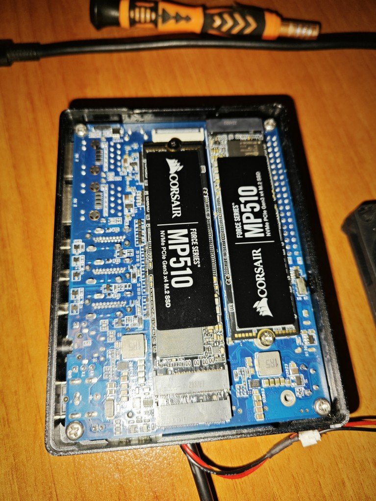
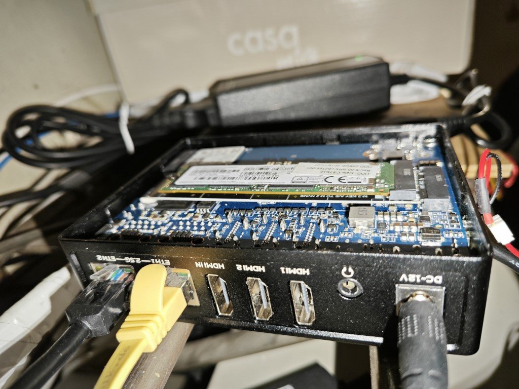
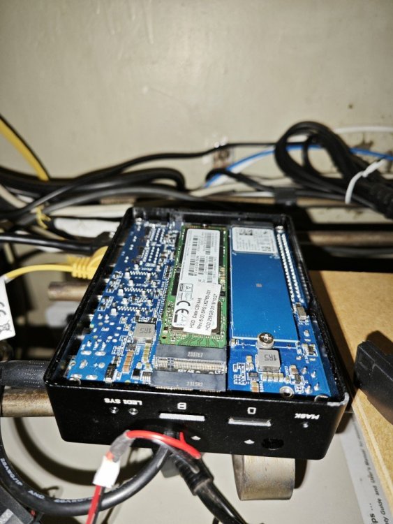
 Hello, I apologize in advance if I haven't put the topic in the right section. I want to share my experience with NanoPC-T6 and two NVMe m.2 disk. I use my NanoPC-T6 for a small server. In the beginning I had 2 SSDs and an M.2 to 2 SATA adapter. But I never found the right solution to power both the NanoPC-T6 and the SSDs from 1 place. After some internet searching I was able to find a solution on how to put 2 NVMe drives on my NanoPC-T6 As you know NanoPC-T6 has 1 M.2 M-Key connector with PCIe 3.0 x4 There is also one PCIe which is M.2 E-key connector with PCIe 2.1 x1 With this adapter: https://www.aliexpress.com/item/1005004762924052.html I am using M.2 E-key to M.2 M-Key. The version of the kernel I use is 6.1.43-vendor-rk35xx. The speed that the NVMe disk on the adapter board can reach is about 400MB per second, which is quite good for my needs. I am attaching some pictures. I hope this is useful for you. If there are any questions, I'm at the meeting to answer them. Regards,

-
Hi all. I made a video about KDE Neon on the Raspberry Pi 5. I love it, I'll be switching from ubuntu-desktop to this. Greetings, NicoD
-
Building Armbian using Ubuntu (jammy) in a systemd-nspawn container https://gist.github.com/ag88/05245121cce37cb8f029424a20752e35 Special thanks goes to @Gunjan Gupta for the tip on PREFER_DOCKER=no
-
 Sharing is caring. Did finally manage to get this working. So lets make it simple clever. Actually i did this on a 64bit raspian light kernel 6.1 but it must be the same on Armbian 10 jan 24 Sharing the Raspberry Pi's WiFi over the ethernet port sudo apt get update && sudo apt install dnsmasq iptables iptables-persistent dhcpcd5 sudo vim /etc/dhcpcd.conf interface eth0 static ip_address=192.168.4.1/24 ------- sudo mv /etc/dnsmasq.conf /etc/dnsmasq.conf.bk sudo nano /etc/dnsmasq.conf - interface=eth0 dhcp-range=192.168.4.8,192.168.4.250,255.255.255.0,12h server=8.8.8.8 bogus-priv ------ sudo systemctl restart dnsmasq.service ------ sudo vim /etc/sysctl.conf net.ipv4.ip_forward=1 ------- sudo systemctl start dnsmasq ------- sudo sh -c "echo 1 > /proc/sys/net/ipv4/ip_forward" ------- sudo iptables -t nat -A POSTROUTING -o wlan0 -j MASQUERADE sudo iptables -A FORWARD -i wlan0 -o eth0 -m state --state RELATED,ESTABLISHED -j ACCEPT sudo iptables -A FORWARD -i eth0 -o wlan0 -j ACCEPT ------- sudo iptables -L -n -v ---------- sudo sh -c "iptables-save > /etc/iptables.ipv4.nat" --------- sudo vim /etc/rc.local iptables-restore < /etc/iptables.ipv4.nat exit0 --------- sudo reboot -------- Did get a perfect internet connection on odroid n2+ through eth0 - so the rpi4b is now supplying wifi for that board and providing petitboot with netbooting images through netboot_default after exit to shell.
 -
Hi all. I made a new video on how to build Armbian images. These days you can use your ARM64 SBC to do this. For Windows users there's WSL2 you can use. Here my video about that. Greetings, NicoD