


gufmar
-
Posts
18 -
Joined
-
Last visited
Content Type
Forums
Store
Crowdfunding
Applications
Events
Raffles
Community Map
Posts posted by gufmar
-
-
10 hours ago, Hijax said:
solution in favor of systemd services
loving this Armbian forum and community. It works great! TYVM
-
I try to build a customized image as described in https://docs.armbian.com/Developer-Guide_User-Configurations/#user-provided-image-customization-script and by using the template with the OpenMediaVault example https://github.com/armbian/build/blob/master/config/templates/customize-image.sh.template
The goal is to build an image who auto-execute an initial setup script after being flashed and frist boot. The device has connected RGB-Leds and an OLED I2c Display on the GPIO pins. It should give color signals durring this initial setup, and then show system parameters (especially the DHCP-Address) on the oled screen *without* having a keyboard and HDMI-Display connected.
It generally works but I have some questions:
crontab @reboot execution only works when I first set a root password and remove the not_logged_in_yet file.
The customize-image function then
- overlays a precompiled dtb file
- creates a shell script file with commands for execution after first boot
- this script is marked as executable
- and finaly added to crontab
this last crontab command returns a "no crontab for root" in the build console, but is then added and also executed. (but only if I first chpasswd the root user)PrepareDevice() { echo root:1234 | chpasswd rm /root/.not_logged_in_yet # I2c tuned to 400kHz cp /tmp/overlay/boot/dtb/rockchip/rk3399-rockpi4b.dtb /boot/dtb/rockchip/rk3399-rockpi4b.dtb mkdir /initial-setup cat > /initial-setup/step1.sh <<- EOF #!/bin/bash # turn blue RGBLed on as a first sign of life cd /sys/class/gpio echo 154 > export cd gpio154 echo out > direction echo 1 > value # setup and configure the I2c OLED display apt-get --yes --force-yes install git git-core build-essential apt-get --yes --force-yes install python-dev python-pil python-smbus python-setuptools python-pip apt-get --yes --force-yes install i2c-tools libi2c-dev lm-sensors pip install psutil # blink as debug info echo 0 > value sleep 1s echo 1 > value # add the OLED script on every future reboot (crontab -u root -l; echo "@reboot python /root/OLEDisplay/sysinfo.py --display sh1106 --i2c-port 2 --rotate 2" ) | crontab -u root - # remove the initial setup on-boot execution crontab -u root -l | grep -v 'initial-setup/step1.sh' | crontab -u root - reboot EOF chmod +x /initial-setup/step1.sh echo "add crontab for step1" # execute the initial-setup shell script on first boot line="@reboot /initial-setup/step1.sh" (crontab -u root -l; echo "$line" ) | crontab -u root - }So far all ok.
The device boots up and the blue led turns on as expected.But then for some (unknown) reason the apt install commands and crontab edits does not work as expected.
It works when I connect a keyboard and HDMI display, log in as root and execute the `/initial-setup/step1.sh`
The question is if there is a general better way or if someone can tell me how to set and remove the crontab scripts ?
-
On 8/5/2019 at 4:42 PM, piter75 said:
One more question.
What revision are your boards?
they are all 1.3
-
17 hours ago, piter75 said:
do you possibly also have an eMMC module?
If so did you have luck using it reliably with model A?
Yes most of all my boards run on eMMC (just started experimenting with the NVME extension)
I never noticed a difference between A and B regarding eMMC behaviour.
I'm not sure if it is related (or my mistake) but 3 from my 8 eMMC cards are not recognised anymore at full size. As they appear with onle 1/8 of size, I guess it is some mistake between 4096 and 512 sector size, happened either on disc resizing after boot, or re-flashing with etcher (on a notebook with weird SDCard driver)
I wasn't able to bring them back to original capacity with whatever operating system, device and partitioning tools I tried. I also tried with a usb-2-emmm adapter but no luck.
But this didn't happen during normal operation, but while playing around, flashing, re-installing. So in my eyes not a Board or eMMC failure.
All other eMMC modules run fine for many months now, with quite a lot of software compilations and benchmarking tests (phoronix). -
On 7/24/2019 at 11:53 PM, martinayotte said:
EDIT2: beware, it seems that any speed lower than 10MHz is not allowed ...
Is this something related to the overlay file, or where do I have the chance to play with this value?
By using the python spidev library I can set something like spi.max_speed_hz=10000000
But I can't see any effect.Also spi.xfer has some factor and it looks like it depends a bit on the HW, wiring and CPU components
    spi.xfer(tx.tolist(), int(4/1.25e-6)) #works, on Zero (initially didn't?)
    #spi.xfer(tx.tolist(), int(4/1.20e-6))  #works, no flashes on Zero, Works on Raspberry 3
    #spi.xfer(tx.tolist(), int(4/1.15e-6))  #works, no flashes on Zero
    #spi.xfer(tx.tolist(), int(4/1.05e-6))  #works, no flashes on Zero
    #spi.xfer(tx.tolist(), int(4/.95e-6))  #works, no flashes on Zero
    #spi.xfer(tx.tolist(), int(4/.90e-6))  #works, no flashes on Zero
    #spi.xfer(tx.tolist(), int(4/.85e-6))  #doesn't work (first 4 LEDS work, others have flashing colors)
    #spi.xfer(tx.tolist(), int(4/.65e-6))  #doesn't work on Zero; Works on Raspberry 3
    #spi.xfer(tx.tolist(), int(4/.55e-6))  #doesn't work on Zero; Works on Raspberry 3
    #spi.xfer(tx.tolist(), int(4/.50e-6))  #doesn't work on Zero; Doesn't work on Raspberry 3 (bright colors)
    #spi.xfer(tx.tolist(), int(4/.45e-6))  #doesn't work on Zero; Doesn't work on Raspberry 3
when I change the timing I can see best (but not perfect) results with 4/.70e-6
As this code example also mentions (first 4 LEDS work) I can only drive the first two LEDs - whatever value I try.
So I wonder if the "base frequency" is set to the optimal value and how I can cange it (without having at hand a singal analyzer to verify)
-
still some fine-tuning required but .... it works !

-
56 minutes ago, martinayotte said:
Did you build a new image with my latest fixes ?
yes. First kernel compilation in my life, worked fine, with expert mode (at least afaik for now ;- )
56 minutes ago, martinayotte said:Did you enabled spi-spidev overlay in /boot/armbianEnv.txt ?
no, will do this evening. I wasn't sure if I need to do this as for I2C in the dts/dtb file (okay) or somewhere else.
Thanks. -
ok, whatever I did, the flashed eMMC booted up and run fine.
But there is still no /dev/spi* device.
Do I need to enable it in the .dts file and recompile to to dtb (similar as with i2c devices) ? -
TIL: there are many branches.
thanks. will try my best. -
22 hours ago, martinayotte said:
I've committed fixes for Rockchip SPI overlays in DEV branch, I've got SPI2 working on my RockPi4B ...
This sounds great! So I while waiting the setup of my new armbuilder vm, I read through the https://docs.armbian.com/Developer-Guide_Build-Process/ and https://docs.armbian.com/Developer-Guide_Build-Options/ and wonder if I need some special options set or if I can just go with defaults?
(I checked out the build repo after your two commits, but as far as I can see it's master, not DEV branch) -
Instead of breaking the (bright) onboard LED's it might be a good idea to use some small piece of black tape.
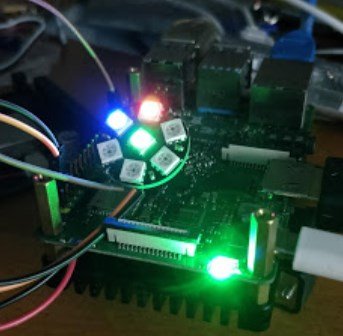
This topic is interesting because I'm also currently working on LEDs on the RockPi. The very bright green LED is very well suited to make the logo appear in a 3d-printed case. But it can only light up in one colour.
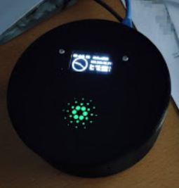
A first problem arises when the M.2 NVME adapter board is screwed on top and hides the green light.
I could connect an RGB LED (cathode) to the GPIOs. But it would need 3 digital (PWM) pins.
So I looked at the small WS2812 LED modules.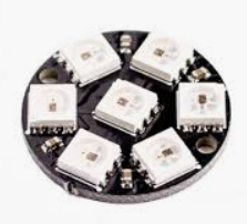
The existing libraries are made for RPi boards with either PWM, PCM or SPI-MISOAs SPI1 on RockPi is used for the SPI-Flash and boot functionality, I tried to enable SPI2 and use Pin 29 (TXD) to generate the serial bit sequence for the WS2812 chips.
With the Help of @martinayotte
...I was able to activate I2C (which in newer releases now is enabled by default) and fill the OLED devices with the LUMA library.
But whatever I tried - by using the current stable or nightly Armbian Bionic build - I wasn't able to se /dev/spi* devices or use them in any other way.
TBH I'm not an expert and have no clear idea what of the following things should or must play together and what are different approaches that shouldn't be mixed.
First I tried to enable SPI in the decompiled .dts file like I did with the I2C port
status = "okay";compatible = "spidev";
spi-max-frequency = <1000000>;
then I also tried to install libmraa and turn on SPI switches in /boot/hw_intfc.conf as described in https://wiki.radxa.com/Rockpi4/dev/libmraa
I guess many other approaches like a layer acting as an universal SBC GPIO library like
or also https://github.com/rahul-thakoor/rust_gpiozero still require the SPI* devices enabled and working at OS level.
I also tried to look into documentations like http://linux-sunxi.org/SPIdev and adopt it to the RockPi specs, but no luck.
So for now it looks more like I must consider to keep my project simple (static green LED and no covering NVME) or I try to get some hints here in this forum...
-
Ah thanks will try again
-
The buster image boots up, and has both Ethernet and Wifi devices enabled.
But no IP packets leave or reach the board, trying both dhcp or static setup, on ipv4 and ipv6.
Ping shows destination unreachable msgs.
Eth0 interface shows up in desktop GUI as well as armbian-config tool and with ip interface command
Switching to an eMMC with bionic image works fine.
-
On 6/13/2019 at 3:03 AM, dolphs said:
Current status appears to be mature, at least from "compile.sh" ?
That is good news, therefore also would like to test a ROCK Pi 4 Model A board ( 2gb and sdcard ) using 5.1 kernel (dev).
I have a and b versions in my lab (all 4GB equipped)
Do you still need some confirmation/verification?
-
Sorry to jump in on this only now (because I only started some weeks ago in trying to bring some gpio-spi stuff to work.
This general SBC library approach looks very interesting to me, and I wonder how experienced GPIO/HW/SW technicians see it? Would it deserve more attention? Or had it some drawbacks because it can't be so low level and direct as device tree, libmraa ecc... ?
I saw the request to post issues on the github repo, but I believe this is not an issue but more a request for better understanding.
-
On 4/8/2019 at 4:13 PM, martinayotte said:
It should be done within the DT using "clock-frequency = <400000>;" in the i2c node, nearby the "status"
perfect solution. works fine. thank you!
For thus who try to C&P the above clock-frequency string: Attention it contains non-standard space chars after the number. So compiling to dtb fil fail with an error. Better use
clock-frequency = <400000>; -
On 3/1/2019 at 4:32 PM, martinayotte said:
You need to install DT compiler from : http://ftp.debian.org/debian/pool/main/d/device-tree-compiler/device-tree-compiler_1.4.7-3_arm64.deb
Backup /boot/dtb/rockchip/rk3399-rockpi4b.dtb into /boot/dtb/rockchip/rk3399-rockpi4b.dtb-ORIG
Decompile the DTB into DTS :
dtc -@ -I dtb -O dts -o rk3399-rockpi4b.dts-4.20.0 /boot/dtb/rockchip/rk3399-rockpi4b.dtbEdit the file rk3399-rockpi4b.dts-4.20.0 by changing all the serial node from "disabled" to "okay", then recompile DTB :
dtc -@ -I dts -O dtb -o /boot/dtb/rockchip/rk3399-rockpi4b.dtb rk3399-rockpi4b.dts-4.20.02Thank you very much, this helped a lot!
some details who may help others: (note: I'm not an expert)
install DT compiler version from the above link, not from online mirrors.
to do so cd into temp directory, curl or wget the above url and chown +x the file as executable
Then install with aptcd /tmp wget http://ftp.debian.org/debian/pool/main/d/device-tree-compiler/device-tree-compiler_1.4.7-3_arm64.deb sudo chmod +x device-tree-compiler_1.4.7-3_arm64.deb sudo apt install device-tree-compiler_1.4.7-3_arm64.debdecompile DTB to DTS as mentioned above.
open the decompiled file and lookup for the interface in the aliases section (e.g. i2c7)
You will find the address (e.g. i2c@ff160000)
scroll down now to this address and verify that status is set to okaystatus = "okay";if not change and re-compile to DTB
As I'm not an expert I wonder if it's possible to change or increase the i2c baudrate to 400 kHz ?
I found descriptions to add
dtparam=i2c_arm=on,i2c_baudrate=400000to /boot/config.txt
As Armbian hasn't this config file I tried to add the same line to /boot/armbianEnv.txt but it doesn't seem to have any effect.
RockPi4b on focal 20.11 stuck on boot at bluetooth
in SD card and PSU issues
Posted
I tested this on multiple v1.3 and 1.4 Boards
In the boot sequence the message appears.
`A start job is running for Bluetooth Rockpi (3min 1s / no limit)`
The boot process continue for other tasks but never completes, even after waiting for hours.
All boards boot fine with 20.08