Ryzer
-
Posts
108 -
Joined
-
Last visited
Content Type
Forums
Store
Crowdfunding
Applications
Events
Raffles
Community Map
Everything posted by Ryzer
-
Hi there, does 'lsmod | grep pdc8544' even show that they module has even load? unfortunately the fbtft drivers are not that well supported hence being in the staging directory. I would advice that you look for a tiny drm based driver which is the way that small displays tend to be handled with the more recent kernel versions best of luck
-
 Hi There, Those overlays are a bit old but should hopefully work with one minor change. Try replacing the compatible field with compatible = "armbian,spi-dev" and see if this works. From what I understand there was a change to the kernel since version 5.15 which removed the old spidev driver. Best of luck Ryzer
 -
Hi there, @FruchtzergGlad to here you got it up and running. Much appreciated, I also learned from you that my cs-gpio node was in the wrong position and correcting got mine up and running. So here is the final revision of my dts overlay: /dts-v1/; /plugin/; /{ compatible = "allwinner,sun4i-a10", "allwinner,sun7i-a20", "allwinner,sun8i-h3", "allwinner,sun50i-a64", "allwinner,sun50i-h5"; fragment@0 { target = <&pio>; __overlay__{ display_pins: display_pins { pins = "PB2", "PI3"; function = "gpio_out", "gpio_out"; }; }; }; fragment@1 { target = <&spi0>; __overlay__ { /* needed to avoid dtc warning */ #address-cells = <1>; #size-cells = <0>; status="okay"; pinctrl-names = "default"; pinctrl-0 = <&spi0_pi_pins>; /* Mux the PI to make sure they are set in spi Mode*/ cs-gpios = <&pio 1 2 0>; /* PB2 (D5) - Linksprite shield TFT CS pin */ num-chipselects = <1>; display: display@0 { compatible = "adafruit,yx240qv29", "ilitek,ili9341"; pinctrl-names = "default"; pinctrl-1 = <&display_pins>; reg = <0>; spi-max-frequency = <12000000>; rotation = <270>; bgr = <0>; fps = <15>; buswidth = <8>; height = <240>; width = <320>; reset-gpios = <&pio 7 9 0>; /* PH9 (D7) */ dc-gpios = <&pio 8 3 0>; /* PI3 (D6) - Data control pin */ debug = <3>; }; }; }; __overrides__ { rotate = <&display>,"rotate:0"; fps = <&display>,"fps:0"; debug = <&display>,"debug:0"; }; }; Would have been interesting to see what they where, not that it ultimately matters now that its working. To get the desktop working you will need to tinker around with the Xorg/Xserver configuration. I have tried to manual trigger it to start but it keeps failing for a reason I have yet to identify other than this currently cryptic error '(EE) FBDEV(0): FBIOPUTCMAP: Device or resource busy' appearing a lot in /var/log/Xorg.0.log Well at least get the the touchscreen to work should be a lot easier now. From what I can see it is I2C based so you can easily get some form of identification from i2c-tools. Again it is configured in the device tree in a similar way to SPI but instead of spidev you have i2c-dev acting as the dummy receiver device. Looking forward to seeing an update with the display working and hopefully the touch panel working. All the best Ryzer
-
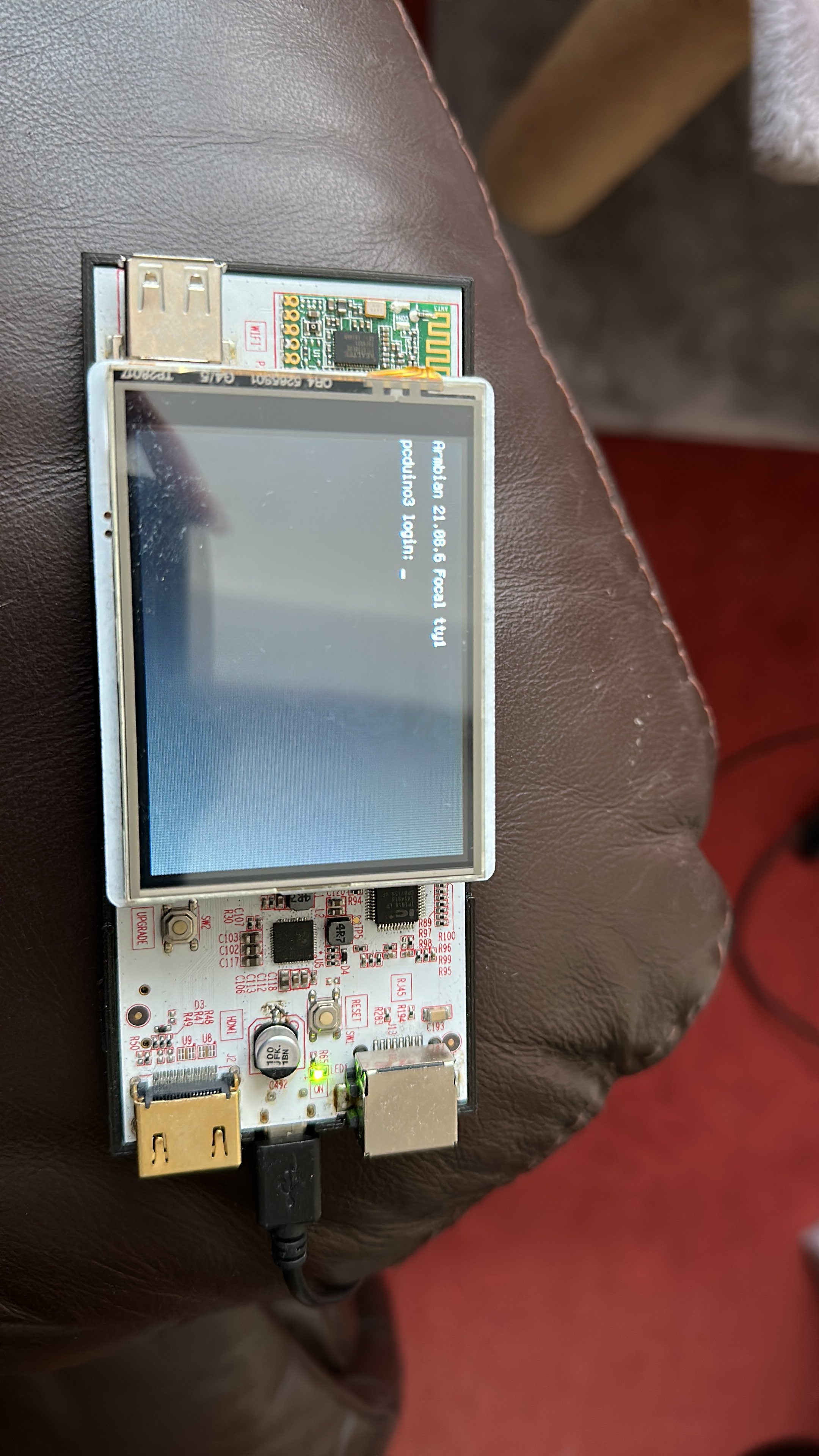
Hi There, Small progress is still progress . Thanks for the offer but not need, auto translate was good enough apart from one or two sentences. Indeed it is very good guide that surprising doesn't refer to the old fb driver or the FBCP library that works on the Raspberry PI only due to direct register interactions. Still not have a lot of luck with my display, still just a white screen just like yours. I wonder if it could perhaps be related to the chip select. Luckily the Pcduino has an led attached to the SPI clock line so I can see clear that data is being sent to the display but nothing else is happening. The display is made by Linksprite but it's basically a clone of the older generation of a display made by Adafruit: https://learn.adafruit.com/adafruit-2-8-tft-touch-shield-v2. Anyway, your overlay looks good. I would just suggest changing the pins used, the guide refers to the BPI-M64 which has different pin map to that used on your BPI-M2. Please see: https://wiki.banana-pi.org/Banana_Pi_BPI-M2_ZERO. If you replace chip select with PA13 and the data control with PC4 then hopefully it should work. You can also change the reset pin to PA2 although I am not sure if the reset line is strictly necessary. Best of luck
-
Hi there, I see that you have enabled spidev which isn't necessary. you just need to enable just the SPI bus which can be done within the overlay. overwise it will just conflict with the ili9341. slightly amended overlay: dts-v1/; /plugin/; /{ compatible = "allwinner,sun4i-a10", "allwinner,sun7i-a20", "allwinner,sun8i-h3", "allwinner,sun50i-a64", "allwinner,sun50i-h5"; fragmen@0 { target = <&pio>; __overlay__ { display_pins: display_pins { pins = "PI11", "PI12"; function = "gpio_out"; }; display_cs_pin: display_cs_pin { pins = "PB2"; function = "gpio_out"; output-high; }; }; }; fragment@1 { target = <&spi0>; __overlay__ { /* needed to avoid dtc warning */ #address-cells = <1>; #size-cells = <0>; status="okay"; num-chipselects = <1>; display: display@0 { compatible = "adafruit,yx240qv29", "ilitek,ili9341"; reg = <1>; spi-max-frequency = <32000000>; pinctrl-names = "default"; pinctrl-0 = <&display_pins>; rotation= <90>; bgr; fps = <25>; buswidth = <8>; height = <240>; width = <320>; /*reset-gpios = <&pio 0 25 0>; */ /* GPIOA 6 */ dc-gpios = <&pio 8 3 0>; /* GPIOA 3 */ cs-gpios = <0>,<&pio 1 2 0>; /* PB2 - Linksprite shield TFT cs pin */ debug = <3>; }; }; }; Just remember to change the pins back to those used bananapiM2 as the current configuration is for my Pcduino. Also could you include a datasheet for your particular display, it would be helpful to know what pins are used for dc and cs.
-
After watching a video tutorial on youtube I have attempted to use the build scripts to create a newer image for my Pcduino V2. I had been initially using an image that I found on the archives which uses kernel 4.14, this worked fine for the most part apart from shutting down which would fail 9/10 to shutdown normally. the only way I could ensure that it would shutdown was to do poweroff -f otherwise it just went into a state where most things such as the wifi and usbs would no longer be detected and i was greeted with the message failed to reach target.poweroff. from what I could find out about the issue suggested that it was some kind of issue with systemd, but I could not find an actual solution. Anyway I thought I would have ago at creating an image, I suppose given the age of the board issues are to be expected. I have had some success in fixes some of the issues encountered despite being relatively new to Armbian and Linux in general. After learning how to create patches, firstly I managed to get UART2 which was originally conflicting with the PMU as they shared the same assigned interrupt number of 3. From what I can tell this different to the normal PMU which I find that the power chip is normally referred to as there also appears to be some internal component within the A10 also called the 'PMU' . This seems to be something to do with core monitor as the A20 chip features 2 of these 'PMU's, one for each core. Looking at the user manual suggest that this should be 49. Now this has been patched I can use UART2 without getting an error although it is exposed as ttyS1 for some reason that I have yet to figure out. The second patch I made was to get HDMI output working which I was able to do by using the Cubieboard as a point of reference as they share similar hardware. I found this out by initially using images targeted at the Cubieboard as they appear to be a lot more recent and provide HDMI out so I knew that copying the sections other would. Additionally I found a way to get it working on my main 4K monitor after coming across a post which suggested lowering the size of the CMA buffer from the default size of 128mb to 64mb. Now again the main problem I face is when I try to shutdown, this time it relates to a kernel panic: [ 2508.547646] WARNING: CPU: 0 PID: 1 at drivers/i2c/i2c-core.h:41 i2c_transfer+ 0x93/0xbc [ 2508.561239] No atomic I2C transfer handler for 'i2c-1' [ 2508.571971] Modules linked in: cfg80211 btusb btintel btrtl btbcm bluetooth a xp20x_adc sun4i_gpadc_iio industrialio lima gpu_sched r8188eu(C) sun4i_ts ecdh_g eneric rfkill ecc joydev input_leds sunxi_cedrus(C) v4l2_mem2mem videobuf2_dma_c ontig videobuf2_memops videobuf2_v4l2 videobuf2_common zram evdev uio_pdrv_genir q display_connector uio cpufreq_dt nfsd auth_rpcgss sch_fq_codel nfs_acl lockd g race sunrpc ip_tables x_tables autofs4 pinctrl_axp209 sun4i_gpadc sunxi phy_gene ric gpio_keys icplus(E) [ 2508.635429] CPU: 0 PID: 1 Comm: systemd-shutdow Tainted: G C E 5 .15.32-sunxi #trunk [ 2508.651044] Hardware name: Allwinner sun4i/sun5i Families [ 2508.663328] [<c010cea9>] (unwind_backtrace) from [<c01095b9>] (show_stack+0x1 1/0x14) [ 2508.678114] [<c01095b9>] (show_stack) from [<c09cc035>] (dump_stack_lvl+0x2b/ 0x34) [ 2508.692774] [<c09cc035>] (dump_stack_lvl) from [<c011b5a9>] (__warn+0xad/0xc0 ) [ 2508.707135] [<c011b5a9>] (__warn) from [<c09c5c23>] (warn_slowpath_fmt+0x5f/0 x7c) [ 2508.721785] [<c09c5c23>] (warn_slowpath_fmt) from [<c0795a5f>] (i2c_transfer+ 0x93/0xbc) [ 2508.736949] [<c0795a5f>] (i2c_transfer) from [<c0795ac3>] (i2c_transfer_buffe r_flags+0x3b/0x50) [ 2508.752981] [<c0795ac3>] (i2c_transfer_buffer_flags) from [<c0697577>] (regma p_i2c_write+0x13/0x24) [ 2508.769489] [<c0697577>] (regmap_i2c_write) from [<c0694023>] (_regmap_raw_wr ite_impl+0x48b/0x560) [ 2508.786008] [<c0694023>] (_regmap_raw_write_impl) from [<c0694139>] (_regmap_ bus_raw_write+0x41/0x5c) [ 2508.802806] [<c0694139>] (_regmap_bus_raw_write) from [<c06939b1>] (_regmap_w rite+0x35/0xc8) [ 2508.818874] [<c06939b1>] (_regmap_write) from [<c06948b5>] (regmap_write+0x29 /0x3c) [ 2508.834263] [<c06948b5>] (regmap_write) from [<c069e723>] (axp20x_power_off+0 x23/0x30) [ 2508.850053] [<c069e723>] (axp20x_power_off) from [<c0137ded>] (__do_sys_reboo t+0xf5/0x16c) [ 2508.866244] [<c0137ded>] (__do_sys_reboot) from [<c0100061>] (ret_fast_syscal l+0x1/0x52) [ 2508.882357] Exception stack(0xc154dfa8 to 0xc154dff0) [ 2508.895490] dfa0: 4321fedc bef4aaa8 fee1dead 28121969 4321f edc 00000000 [ 2508.911883] dfc0: 4321fedc bef4aaa8 bef4aaa4 00000058 bef4aaa8 bef4aaa4 fffff 000 bef4aaac [ 2508.928357] dfe0: 00000058 bef4aa1c b6eb81b5 b6e367e6 [ 2508.941715] ---[ end trace 8381275b8efb7dea ]--- [ 2510.584023] i2c i2c-1: mv64xxx: I2C bus locked, block: 1, time_left: 0 [ 2511.128016] Kernel panic - not syncing: Attempted to kill init! exitcode=0x00 000000 [ 2511.175494] CPU: 0 PID: 1 Comm: systemd-shutdow Tainted: G WC E 5 .15.32-sunxi #trunk [ 2511.192848] Hardware name: Allwinner sun4i/sun5i Families [ 2511.206836] [<c010cea9>] (unwind_backtrace) from [<c01095b9>] (show_stack+0x1 1/0x14) [ 2511.223311] [<c01095b9>] (show_stack) from [<c09cc035>] (dump_stack_lvl+0x2b/ 0x34) [ 2511.239614] [<c09cc035>] (dump_stack_lvl) from [<c09c5a4d>] (panic+0xc1/0x238 ) [ 2511.255555] [<c09c5a4d>] (panic) from [<c011fd5d>] (complete_and_exit+0x1/0x1 8) [ 2511.271612] [<c011fd5d>] (complete_and_exit) from [<fee1dead>] (0xfee1dead) [ 2511.287376] ---[ end Kernel panic - not syncing: Attempted to kill init! exit code=0x00000000 ]--- I have seen 1 or 2 other post which appear to be a similar issue. Aside from that SPI does not work, but I gather this is currently a more general issue due to changes in the way the SPIDEV works. it's strange, I can enable the overlay and specify the bus and it shows up under /dev as expected but it does not appear to be sending any date when try to interface with LCD screen. I did a loopback test and it return all zero as if the pins where disconnected. The last version I found it correctly worked on was a Cubieboard image with kernel 5.10. I did come across one post which suggested a possible fix although I'm not sure if this has been implemented yet. I know this probably a bit of a length first post but thanks for taking the time to read and I look forward to hear suggestions of where to start looking next as I know I still have a lot to learn. Here are the logs: http://ix.io/46XA cheers Ryzer