Search the Community
Showing results for tags 'bananapim2zero'.
Found 16 results
-
 I'm unable to make an RTC module to work: RTC module ds3231, BPI M2Z and ARMBIAN Bookworm i2c pins 3 and 5 Driver RTC-ds1307 loaded, because RTC-ds3231 is not available. Why do I need a RTC-module? Often in the field I'm not online but I do need the right time on my observation camera's. My application does not allow me for having a monitor. My system does the recordings by motion detection, and the recordings do need the right time on it. armbian-config i2c0 set Tools installed: apt install python3-smbus i2c-tools i2cdetect -y 0 Detects address 068 and not UU as proof of driver been loaded File "hwclock-set" adapted #if [ -e /run/systemd/system ] ; then # exit 0 #fi Fake hwclock removed sudo apt -y remove fake-hwclock sudo update-rc.d -f fake-hwclock remove armbianEnv.txt overlay and dtoverlay correctly set modules.conf added: rtc-ds1307 Still, after a power down, the hardware clock shows 1970 as the date The same module tested on my RPi Zero 2W, and all is working perfect. If somebody can help me, that would be wonderful.
 -
I hope the topic is on the right place ? It should only be a hint ! Kernel 6.12.20 for the banana Pi M2 zero doesn't support USB. I fixed this by reinstalling kernel v6.6.75. Regards Bernd
-
 Dear Community, I'll build a Developer Team specially for Banana Pi Boards!" GPIO Libarys I started updating/modifing the old GPIO-Libarys, so they can be used on the latest builds! I want to build a Team, for GPIO-Libary Development, for porting these Libarys: WiringPi-Node WiringPi-PHP WiringPi-Perl WirinigPi-Ruby gpiozero rpi-gpio Updating and modifying these: RPi.GPIO BPI-WiringPi2-Python BPI-WiringPi2 At the end, all currently working GPIO Libarys are: luma.oled RPi.GPIO BPI-WiringPi BPI-WiringPi2 BPI-WiringPi2-Python Armbian Build System for Banana Pi I started building the build-system for full banana pi support! Anyone who would like to join the developer-team, just pn me, post in this thread, or contact me on github or discord!" I created a GIthub-Organisation for this project and a Discord Server. A Domain & VPS Server is commin Monday!" Goals: Support ONLY for Banana Pi Boards Board Determiner Script which exports Board-Infos, required by gpio-libs (usual located at: /var/lib/bananapi) APT-Mirror Archive Hosted by our project-teams vps-server! ( Mirror stores all latest gpio-libarys we specially build for using on latest builds and other packages we'll develope in future) Added APPGROUPS: Pentesting, TV-Box, Server-Side, Game Desk & Development Revised menu for selecting extensions and other additional items Revised config menu Adding additional build options A Web-Based Project-Server Hosted Build-System will be build and available on the project-page, where you can build images remotely, according to you settings made in the WebInterface, with live progress & build-log + downloading compressed own image-release. A publish option will be added to, where you can upload your builded image to any Cloud/Storage we provide. Revised device trees According to APPGROUPS and Enabled Extensions: I2C, SPI, UART are enabled in the gpio_develope extension, and all requirements for gpio-programming are pre-installed, the gpio libs are pre-installed too. If you have some Ideas, what we could add or which wishes we can make true, just reply in this post, or contact us. Github Organisation Discord greetz, hexzhen3x7
 -
 Hello, I am curious to hear how accurate the measurement of temperature is from the onboard sensors, particularly in my case for the Banana Pi M2+. While I do understand that the BPi M2+ suffered from poor choices for thermal management from the manufacturer both in hardware and software, I believe that thankfully Armbian has worked out the kinks on the software side, hasn't it? I am running the latest noble image, here's what I noticed. The temperature as shown by the sensors and armbianmonitor commands never really goes below 60° even on idle with ambient temperatures of around 25 to 30 degrees. My SBC already came with a small heatsink attached to the CPU. I found that value pretty high and inquired with an infrared thermometer but couldn't really find a spot on the board over 40°. Which makes me wonder if the reading is accurate and properly calibrated? My impression is that it is not. Furthermore, I noticed the board behaves quite well under load. For example, I stress-tested it with the yes command on all cores for about an hour or so and while the temperature went up to 95°, it appears the software was well-tweaked to only slightly throttle the CPU (verified with armbianmonitor -m) to not exceed this. I am not 100% sure about the thermometer readings, but I believe they were around 60° at the time, certainly nowhere near what sensors was showing. I have been testing the board for about a week now and I have to say that one time, the board did indeed shut down due to thermal overload. Interestingly, this wasn't even when the CPU was heavily loaded but there was a lot of IO wait. Temperature was high and it briefly shot up to 101° (ouch) which triggered an emergency shutdown to prevent thermal damage. Looked good to me, mostly. So, again, my question today is how trustworthy are the readings from the sensors, are they properly calibrated?
 -
Hello Community! I am struggling with assigning numbers to I2C buses in my BPi, doing the same(?) thing in two different ways i am getting two different results. By default, there is only /dev/i2c-0 node available, AFAIK because HDMI uses this bus. 1. Using build-in overlay for i2c0 bus (overlays=i2c0 in /boot/armbianEnv.txt) enables another i2c bus. In this case, /dev/i2c-0 is the bus connected to pins 3 and 5 at 40-pin header. The other bus (enabled by default) becomes /dev/i2c-1. It doesn't matter how many times i reset my board, assignment doesn't change. 2. The second way is to create my own overlay by cloning this code and compiling it with armbian-add-ovelray command. It also enables another i2c bus. However, in this case the buses are swapped, /dev/i2c-0 doesn't change, the newly created bus is /dev/i2c-1 and works fine with sensors connected to pins 3 and 5. This enumeration also doesn't change after reboot. Can someone tell me why does it happens? Does the cod for build-in overlay differ from the shared one? Please, be patient for newbie user Here is the version: cat /etc/armbian-release # PLEASE DO NOT EDIT THIS FILE BOARD=bananapim2zero BOARD_NAME="Banana Pi M2 Zero" BOARDFAMILY=sun8i BUILD_REPOSITORY_URL=https://github.com/armbian/build BUILD_REPOSITORY_COMMIT=7184c5aa8 LINUXFAMILY=sunxi ARCH=arm BOOT_SOC= IMAGE_TYPE=stable BOARD_TYPE=csc INITRD_ARCH=arm KERNEL_IMAGE_TYPE=zImage KERNEL_TARGET=legacy,current,edge KERNEL_TEST_TARGET=current FORCE_BOOTSCRIPT_UPDATE= FORCE_UBOOT_UPDATE= OVERLAY_DIR="/boot/dtb/allwinner/overlay" VENDOR="Armbian" VENDORDOCS="https://docs.armbian.com" VENDORURL="https://www.armbian.com/" VENDORSUPPORT="https://forum.armbian.com" VENDORBUGS="https://www.armbian.com/bugs" BOOTSCRIPT_FORCE_UPDATE="no" BOOTSCRIPT_DST="boot.cmd" VERSION=25.2.2 REVISION=25.2.2 BRANCH=current
-
Hi, It is very hard to start OS (community version, downloaded from here). The system doesn't start at all, if the keyboard is already attached. I've discovered some magic moment during the startup process, when I can attach keyboard and system goes further. In most of moments the boot process stops, as soon as I'm attaching the keyboard. Lines are scrolled too fast to let me note what moment is "successful". Also I've noticed that the chip is very hot, when the keyboard is attached. It's much colder when keyboard is detached. Another small issue is that functional keys don't work. Though Ctrl/Alt and other similar keys do. My keyboard is an "aluminum" Apple keyboard. Didn't try other. Also I wonder if there is any way to change screen resolution for console. It looks like environment setting doesn't take effect. Only 1920x1080 resolution works. It's not so suitable for me.
-
I am trying to build Armbian using command below. I use 25.02.0-trunk armbian build version in docker. However I don't get kernel source package after succesful building. I get only following debs: armbian-bsp-cli-bananapim2zero_25.02.0-trunk_armhf__1-PC7e64-V62c4-H9299-B6e44-R7697.deb armbian-bsp-cli-bananapim2zero-current_25.02.0-trunk_armhf__1-PC7e64-V62c4-H9299-B6e44-R7697.deb armbian-config_25.02.0-trunk_all__1-SAfdf5-B8c21-R448a.deb armbian-firmware_25.02.0-trunk_all__1-SA8dbb-B6c7f-R448a.deb fake-ubuntu-advantage-tools_25.02.0-trunk_all__1-B34ac-R448a.deb linux-dtb-current-sunxi_25.02.0-trunk_armhf__6.6.65-S943e-D0531-P78f8-Cc98cH5c21-HK01ba-V014b-B59f0-R448a.deb linux-headers-current-sunxi_25.02.0-trunk_armhf__6.6.65-S943e-D0531-P78f8-Cc98cH5c21-HK01ba-V014b-B59f0-R448a.deb linux-image-current-sunxi_25.02.0-trunk_armhf__6.6.65-S943e-D0531-P78f8-Cc98cH5c21-HK01ba-V014b-B59f0-R448a.deb linux-libc-dev-current-sunxi_25.02.0-trunk_armhf__6.6.65-S943e-D0531-P78f8-Cc98cH5c21-HK01ba-V014b-B59f0-R448a.deb linux-u-boot-bananapim2zero-current_25.02.0-trunk_armhf__2024.01-S866c-Pf814-Ha5c2-Vc5a9-Bdacf-R448a.deb I remember getting source package after building armbian 2 years ago ./compile.sh \ BOARD=bananapim2zero \ BRANCH=current \ RELEASE=noble \ BUILD_MINIMAL=yes \ BSPFREEZE=yes \ OFFLINE_WORK=yes \ BUILD_KSRC=yes \ KERNEL_CONFIGURE=no \
-
 Hello guys, i'm trying to connect that ili9341 display with my m2 zero but it wont work. My armbian Version: Armbian_23-02-0-trunk_Bananapim2zero_lunar_edge_6.1.11_xfce_desktop The display has a pinout that matches with the raspberry pi, so also the banana pi m2 zero would do the job, since it has the same pinout like the raspberry pi has. It uses 26 pins to connect to the banana pi m2 zero gpio output pins. 3 buttons and a touch panel are available but i only want to use the lcd for now. I edited the armbianEnv.txt to open the spi port and added my overlay tft.dts to /boot/overlay-user but i cant get a picture on the screen, Its just glowing white. Am I missing something? Are my gpios numbers in the overlay correct? do i have to install additional software? I would be very happy for tips or help! My armbianEnv.txt : verbosity=1 bootlogo=false console=both disp_mode=1920x1080p60 overlay_prefix=sun8i-h3 rootdev=UUID=39f6ab06-e14f-4885-8454-717c5405f006 rootfstype=ext4 overlays=cpu-clock-1.2GHz-1.3v spi-spidev param_spidev_spi_bus=0 user_overlays=tft usbstoragequirks=0x2537:0x1066:u,0x2537:0x1068:u My overlay tft.dts /dts-v1/; /plugin/; / { compatible = "allwinner,sun4i-a10", "allwinner,sun7i-a20", "allwinner,sun8i-h3", "allwinner,sun50i-a64", "allwinner,sun50i-h5"; fragmen@0 { target = <&pio>; __overlay__ { display_pins: display_pins { pins = "PC0", "PC3"; function = "gpio_out"; }; }; }; fragment@1 { target = <&spi0>; __overlay__ { /* needed to avoid dtc warning */ #address-cells = <1>; #size-cells = <0>; display: display@0 { compatible = "adafruit,yx240qv29", "ilitek,ili9341"; reg = <0>; pinctrl-names = "default"; pinctrl-0 = <&display_pins>; spi-max-frequency = <16000000>; rotation= <270>; bgr; fps = <10>; buswidth = <8>; height = <240>; width = <320>; reset-gpios = <&pio 0 25 0>; /* GPIOA 6 */ dc-gpios = <&pio 0 24 0>; /* GPIOA 3 */ debug = <3>; }; }; }; __overrides__ { rotation = <&display>, "rotation:0"; fps = <&display>, "fps:0"; debug = <&display>, "debug:0"; }; };
 -
Hi All, I''m using a BPI M2 Zero, where a 100 MBit ethernet Interface is implemented on the board. Since I'm using DHCP for this interface, I found that the MAC Address of this eth0 interface changes on every boot. The MAC Address of the wlan0 interface is permanent and don't changes during boots. ~~~~~~~~~~~~~~~~~~~~~~~~~~~~~~~~~~~~~~~~~~~~~~~~~~~~~~~~~~~~~~~ Di 30. Jun xx:xx:xx CEST 2020 Debian GNU/Linux 10 (buster) 5.4.45-sunxi ~~~~~~~~~~~~~~~~~~~~~~~~~~~~~~~~~~~~~~~~~~~~~~~~~~~~~~~~~~~~~~~ 17:42:11 up 25 min, 2 users, load average: 0,00, 0,00, 0,05 eth0: flags=4163<UP,BROADCAST,RUNNING,MULTICAST> mtu 1500 ether 8a:aa:ea:69:67:50 txqueuelen 1000 (Ethernet) wlan0: flags=4163<UP,BROADCAST,RUNNING,MULTICAST> mtu 1500 ether cc:b8:a8:a9:bc:8e txqueuelen 1000 (Ethernet) 17:46:04 up 0 min, 2 users, load average: 2,48, 0,70, 0,24 eth0: flags=4163<UP,BROADCAST,RUNNING,MULTICAST> mtu 1500 ether 5e:af:c0:93:75:72 txqueuelen 1000 (Ethernet) wlan0: flags=4163<UP,BROADCAST,RUNNING,MULTICAST> mtu 1500 ether cc:b8:a8:a9:bc:8e txqueuelen 1000 (Ethernet) 17:47:07 up 0 min, 2 users, load average: 1,92, 0,44, 0,14 eth0: flags=4163<UP,BROADCAST,RUNNING,MULTICAST> mtu 1500 ether 56:e7:62:af:35:55 txqueuelen 1000 (Ethernet) wlan0: flags=4163<UP,BROADCAST,RUNNING,MULTICAST> mtu 1500 ether cc:b8:a8:a9:bc:8e txqueuelen 1000 (Ethernet) 17:48:23 up 0 min, 2 users, load average: 1,69, 0,39, 0,13 eth0: flags=4163<UP,BROADCAST,RUNNING,MULTICAST> mtu 1500 ether 96:57:7c:ed:85:e0 txqueuelen 1000 (Ethernet) wlan0: flags=4163<UP,BROADCAST,RUNNING,MULTICAST> mtu 1500 ether cc:b8:a8:a9:bc:8e txqueuelen 1000 (Ethernet) Is there a way to set the MAC address of the eth0 interface to a fix value ? Regards WolliK
-
I am listed as the community maintainer for the Banana Pi M2 Zero. I haven't actually done any maintaining but I am thinking about doing so now. But before I do, a couple of quick questions. 1) The latest build (as far as I can see), is Aug-31st, 2023. Do I have that right? Or am I missing something? 2) The main page for the Banana Pi M2 Zero (https://www.armbian.com/bananapi-m2-zero/) shows a link to Armbian_community_24.11.0-trunk.273_Bananapim2zero_bookworm_current_6.6.54_minimal.img.xz which is for "Minimal/IOT images with Armbian Linux v6.6". Is that a generic build for all community maintained sunxi hardware? Or is that a specific Banana Pi M2 Zero build and I just don't know where the main builds are stored? 3) I happen to like the Banana Pi M2 zero but are there are reasons that anyone can think of that makes it a waste of my time to maintain this older board? Apologies for the basic questions. I am trying to get up to speed so that I can begin contributing to Armbian. UPDATE: I answered questions 1 and 2 by referring to the https://docs.armbian.com/Board_Maintainers_Procedures_and_Guidelines/ page. And, I answered question three myself. The Banana Pi M2 Zero is still manufactured and sold as of 2024 and I use it in one of my products. So I will get down to the business of supporting it with Armbian.
-
Hi, I recently purchased a Banana Pi M2 zero, and I can't seem to get the OTG port to work with any kind of operating system. I have tried all of the normal remedies like cable issues, power supply, etc. With no luck. I know Armbian is usually the best OS for these little boards, but I can't seem to get a keyboard or mouse to work with it. Although it boots up just fine. Any help would be greatly appreciated!
-
After flashing the sd card with armbian and booting it, it asks me to enter the root password, however the keyboard that is plugged in isnt detected and nothing is typed on the screen. Ive already tried bookworm and jammy, both cli and minimal-cli variants. It is not a keyboard or usb related issue, i tested it with an older version of armbian and the keyboard still works.
-
Hello, I installed 2022-09-27-Armbian_22.11.0-trunk_jammy_edge_lubuntu_5.19.6-qt5-swap-bpi-p2z-10804MB.img on my Banana Pi Zero and it works great! I run sudo apt update , sudo apt upgrade ... Hours later, time to reboot. The board reboots and crashes.. See pic. Hmmm can't attach pics for some reason. First error I see on the screen says Failed to load '/boot/dtb/sun8i-h2-plus-bananapi-p2-zero.dtb libfdt fdt_check_header(): FDT_ERR_BADMAGIC No FDT memory address configured. Please configure the FDT address via "fdt addr <address>" command. Aborting! Then a bunch of other errors ERROR: Did not find a cmdline Flattened Device Tree Could not find a valid device tree Script failures.. No ethernet found.. Eventually => Also had some fun fixing the github public key before I was able to do apt update.
-
Hello, community. For a while now, I've been trying to configure the input and output of i2s0 without success. The closest I've come to a result was with the adau7002 configuration, but I'm experiencing synchronous noise, as if the issue were related to a CLK. Let me provide some details to see if anyone can guide me. I have a Banana Pi M2 with Armbian 23.11.1 Bookworm and Linux 6.1.13-current-sunxi. I have a pcm1807 connected to the input, configured with SPI, outputting i2s left justified in 24bit, and operating as a master. The pcm is connected to a 24.5MHz crystal. My goal is to configure the system to capture audio in a generic i2s format and then play it back in the same way through the output, as I have an amplifier connected to it. My other question is whether it's possible to reconfigure the pins using an overlay. Currently, my pin configuration is as follows: PA10 = LRCLK PA16 = BCLK PA20 = SDI PA21 = SDO i tried reconfigure the pins but i couldn't ☹️ I am attaching the adau7002.dts to provide additional information: /dts-v1/; /plugin/; / { compatible = "allwinner,sun8i-h3"; fragment@0 { target-path = "/"; __overlay__ { adau7002_codec: adau7002_codec { #sound-dai-cells = <0>; compatible = "adi,adau7002"; status = "okay"; }; }; }; fragment@1 { target = <&i2s0>; __overlay__ { status = "okay"; pinctrl-0 = <&i2s0_pins>; sound-dai = <&adau7002_codec>; pinctrl-names = "default"; }; }; fragment@2 { target-path = "/"; __overlay__ { sound_i2s { compatible = "simple-audio-card"; simple-audio-card,format = "i2s"; simple-audio-card,name = "adau7002"; #simple-audio-card,dai-link = "left_j"; simple-audio-card,bitclock-slave = <&dailink0_slave>; simple-audio-card,frame-slave = <&dailink0_slave>; simple-audio-card,mclk-fs = <512>; simple-audio-card,widgets = "Line", "Line In Jack"; simple-audio-card,routing = "PDM_DAT", "Line In Jack"; status = "okay"; simple-audio-card,cpu { sound-dai = <&i2s0>; }; dailink0_slave: simple-audio-card,codec { sound-dai = <&adau7002_codec>; }; }; }; }; }; I use for capture this command: "arecord -D hw:0,0 -f S16_LE -t wav -r 48000 -c 2 -d 10 -V stereo -v >test.wav". But when I want to switch S16_LE to S24_LE you can hardly hear anything, although the noise persists with both formats
-
Hello, I'm using a BPI M2 Zero (with H3 Chip) to control two relays on CON2-P05 / PA11 and CON2-P03 / PA12. During the boot process there is a high level present at the pins, which is driving the relays. Is there a way to create a DTB overlay to drive the pins to a low level during boot. My userspace application uses libgpiod to control the pins. I'm familiar with compiling and activating overlays, i would just need help to write the correct .dts file. Thank you very much in advance
-
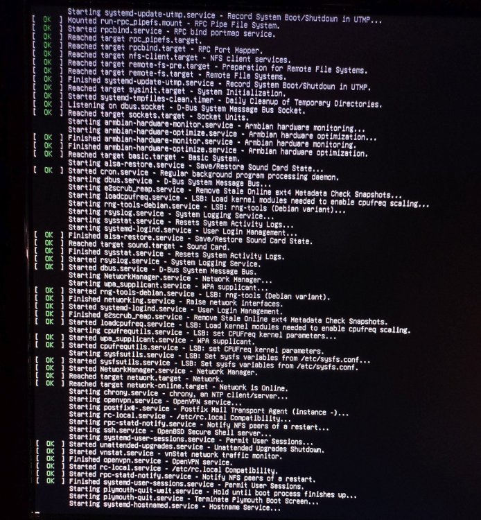
I am running bookworm on a banana pi m2 zero. It comes up properly and connects to Wifi and to the attached LAN adapter, so I can access it via SSH on both interfaces. BUT, when I disconnect the keyboard, it doesn't boot properly anymore and I cannot connect to it. I attached a monitor to take a look at the startup messages and found that it hangs at starting the hostname service (see screenshot) How can I get it to boot properly?