Search the Community
Showing results for tags 'pcduino2'.
Found 3 results
-
After watching a video tutorial on youtube I have attempted to use the build scripts to create a newer image for my Pcduino V2. I had been initially using an image that I found on the archives which uses kernel 4.14, this worked fine for the most part apart from shutting down which would fail 9/10 to shutdown normally. the only way I could ensure that it would shutdown was to do poweroff -f otherwise it just went into a state where most things such as the wifi and usbs would no longer be detected and i was greeted with the message failed to reach target.poweroff. from what I could find out about the issue suggested that it was some kind of issue with systemd, but I could not find an actual solution. Anyway I thought I would have ago at creating an image, I suppose given the age of the board issues are to be expected. I have had some success in fixes some of the issues encountered despite being relatively new to Armbian and Linux in general. After learning how to create patches, firstly I managed to get UART2 which was originally conflicting with the PMU as they shared the same assigned interrupt number of 3. From what I can tell this different to the normal PMU which I find that the power chip is normally referred to as there also appears to be some internal component within the A10 also called the 'PMU' . This seems to be something to do with core monitor as the A20 chip features 2 of these 'PMU's, one for each core. Looking at the user manual suggest that this should be 49. Now this has been patched I can use UART2 without getting an error although it is exposed as ttyS1 for some reason that I have yet to figure out. The second patch I made was to get HDMI output working which I was able to do by using the Cubieboard as a point of reference as they share similar hardware. I found this out by initially using images targeted at the Cubieboard as they appear to be a lot more recent and provide HDMI out so I knew that copying the sections other would. Additionally I found a way to get it working on my main 4K monitor after coming across a post which suggested lowering the size of the CMA buffer from the default size of 128mb to 64mb. Now again the main problem I face is when I try to shutdown, this time it relates to a kernel panic: [ 2508.547646] WARNING: CPU: 0 PID: 1 at drivers/i2c/i2c-core.h:41 i2c_transfer+ 0x93/0xbc [ 2508.561239] No atomic I2C transfer handler for 'i2c-1' [ 2508.571971] Modules linked in: cfg80211 btusb btintel btrtl btbcm bluetooth a xp20x_adc sun4i_gpadc_iio industrialio lima gpu_sched r8188eu(C) sun4i_ts ecdh_g eneric rfkill ecc joydev input_leds sunxi_cedrus(C) v4l2_mem2mem videobuf2_dma_c ontig videobuf2_memops videobuf2_v4l2 videobuf2_common zram evdev uio_pdrv_genir q display_connector uio cpufreq_dt nfsd auth_rpcgss sch_fq_codel nfs_acl lockd g race sunrpc ip_tables x_tables autofs4 pinctrl_axp209 sun4i_gpadc sunxi phy_gene ric gpio_keys icplus(E) [ 2508.635429] CPU: 0 PID: 1 Comm: systemd-shutdow Tainted: G C E 5 .15.32-sunxi #trunk [ 2508.651044] Hardware name: Allwinner sun4i/sun5i Families [ 2508.663328] [<c010cea9>] (unwind_backtrace) from [<c01095b9>] (show_stack+0x1 1/0x14) [ 2508.678114] [<c01095b9>] (show_stack) from [<c09cc035>] (dump_stack_lvl+0x2b/ 0x34) [ 2508.692774] [<c09cc035>] (dump_stack_lvl) from [<c011b5a9>] (__warn+0xad/0xc0 ) [ 2508.707135] [<c011b5a9>] (__warn) from [<c09c5c23>] (warn_slowpath_fmt+0x5f/0 x7c) [ 2508.721785] [<c09c5c23>] (warn_slowpath_fmt) from [<c0795a5f>] (i2c_transfer+ 0x93/0xbc) [ 2508.736949] [<c0795a5f>] (i2c_transfer) from [<c0795ac3>] (i2c_transfer_buffe r_flags+0x3b/0x50) [ 2508.752981] [<c0795ac3>] (i2c_transfer_buffer_flags) from [<c0697577>] (regma p_i2c_write+0x13/0x24) [ 2508.769489] [<c0697577>] (regmap_i2c_write) from [<c0694023>] (_regmap_raw_wr ite_impl+0x48b/0x560) [ 2508.786008] [<c0694023>] (_regmap_raw_write_impl) from [<c0694139>] (_regmap_ bus_raw_write+0x41/0x5c) [ 2508.802806] [<c0694139>] (_regmap_bus_raw_write) from [<c06939b1>] (_regmap_w rite+0x35/0xc8) [ 2508.818874] [<c06939b1>] (_regmap_write) from [<c06948b5>] (regmap_write+0x29 /0x3c) [ 2508.834263] [<c06948b5>] (regmap_write) from [<c069e723>] (axp20x_power_off+0 x23/0x30) [ 2508.850053] [<c069e723>] (axp20x_power_off) from [<c0137ded>] (__do_sys_reboo t+0xf5/0x16c) [ 2508.866244] [<c0137ded>] (__do_sys_reboot) from [<c0100061>] (ret_fast_syscal l+0x1/0x52) [ 2508.882357] Exception stack(0xc154dfa8 to 0xc154dff0) [ 2508.895490] dfa0: 4321fedc bef4aaa8 fee1dead 28121969 4321f edc 00000000 [ 2508.911883] dfc0: 4321fedc bef4aaa8 bef4aaa4 00000058 bef4aaa8 bef4aaa4 fffff 000 bef4aaac [ 2508.928357] dfe0: 00000058 bef4aa1c b6eb81b5 b6e367e6 [ 2508.941715] ---[ end trace 8381275b8efb7dea ]--- [ 2510.584023] i2c i2c-1: mv64xxx: I2C bus locked, block: 1, time_left: 0 [ 2511.128016] Kernel panic - not syncing: Attempted to kill init! exitcode=0x00 000000 [ 2511.175494] CPU: 0 PID: 1 Comm: systemd-shutdow Tainted: G WC E 5 .15.32-sunxi #trunk [ 2511.192848] Hardware name: Allwinner sun4i/sun5i Families [ 2511.206836] [<c010cea9>] (unwind_backtrace) from [<c01095b9>] (show_stack+0x1 1/0x14) [ 2511.223311] [<c01095b9>] (show_stack) from [<c09cc035>] (dump_stack_lvl+0x2b/ 0x34) [ 2511.239614] [<c09cc035>] (dump_stack_lvl) from [<c09c5a4d>] (panic+0xc1/0x238 ) [ 2511.255555] [<c09c5a4d>] (panic) from [<c011fd5d>] (complete_and_exit+0x1/0x1 8) [ 2511.271612] [<c011fd5d>] (complete_and_exit) from [<fee1dead>] (0xfee1dead) [ 2511.287376] ---[ end Kernel panic - not syncing: Attempted to kill init! exit code=0x00000000 ]--- I have seen 1 or 2 other post which appear to be a similar issue. Aside from that SPI does not work, but I gather this is currently a more general issue due to changes in the way the SPIDEV works. it's strange, I can enable the overlay and specify the bus and it shows up under /dev as expected but it does not appear to be sending any date when try to interface with LCD screen. I did a loopback test and it return all zero as if the pins where disconnected. The last version I found it correctly worked on was a Cubieboard image with kernel 5.10. I did come across one post which suggested a possible fix although I'm not sure if this has been implemented yet. I know this probably a bit of a length first post but thanks for taking the time to read and I look forward to hear suggestions of where to start looking next as I know I still have a lot to learn. Here are the logs: http://ix.io/46XA cheers Ryzer
-
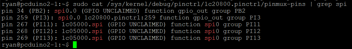
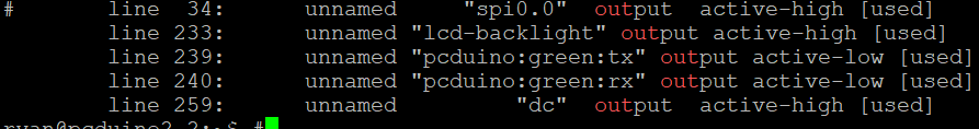
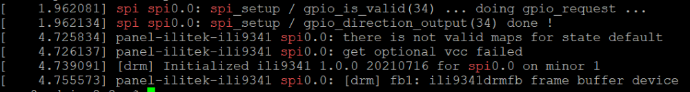
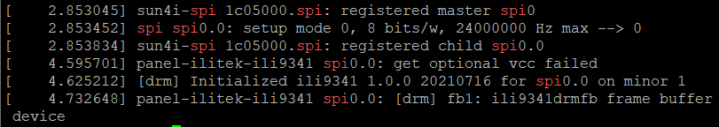
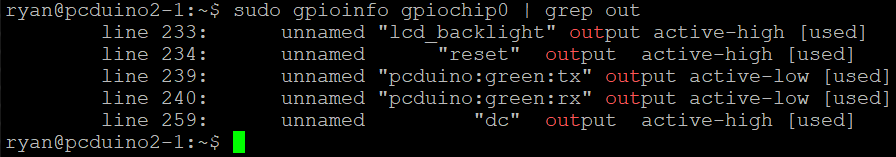
I have recently been trying to get my spi ili9341 working under kernel 6.6, having gotten it working previously. I checked to ensure there were no changes in the overlay required by the newer kernel. I confirmed that the pins were configured correctly and that the ILI9341 DRM module had loaded.. Despite this I was met with a white screen. Think I must have missed something I swapped out my SD card for another using an image based on kernel 5.15.88, where I was able to recieve a display. Looking back over the dmesg log, I noticed a slight difference in behaviour with the older kernel. firstly we can clearly see that the SPI driver is requesting to use gpio 34 as a chip select line compared to kernel 6.6. Secondly using gpioinfo to see which pins are currently set as output, to observe if gpio 34 has been set. A slight draw back with this approach is that it does not currently acknowledge when gpio are configured for spi. Kernel 5.15.88: Kernel 6.6.16: I later tried again but with my Pcduino3 using a more recent build based on kernel of 6.6.44 but achieved the same result. To confirm my theory that the problem lies somewhere within the chip select intialisation, I temporarily rerouted the pin used for the display to the Pcduino's native chip select pin (PI10) and recompiled the overlay to match. Now when I booted the pcduino I was met with a terminal window.
-
When testing my most recent builds using the Armbian build framework I found that I was experiencing a constant load greater than 1.00. At first, I thought this is probably normal to have a load during the system boot but after waiting over 10 minutes I found that the load did not decrease. Firstly, I used HTOP but could not find a process that was heavy utilising the CPU with the relative CPU usage show as low. Next I tried using TOP which revealed a process called kworker: freezeable_power. Trying to search for the issue I did not find much until I came across this old forum post that described the same issues I was having: https://forum.armbian.com/topic/7575-k-worker-problem-on-a20-based-boards/page/2/ Sure enough, removing the sun4i-gpadc caused the average system load to drop and even relative CPU usage dropped to around 1% utilisation rather than the usual idling around 20 – 25%. The risk is losing the CPU temperature. Following the advice from the latest post I found that setting mode to disabled seemed to do the trick of bringing down the system load while retaining CPU temperature reading. I achieved this by modifying rc.local with the line: Echo disabled > /sys/devices/virtual/thermal/thermal_zone1/mode Admittedly this works reasonably well however it take around approximately 5 minutes for system load to drop down to a more expected 15% - 20% on idle. I am hoping that someone with an understanding of the touchscreen control on the A10/A20 may be able to provide a fix as this out of my depth with my current knowledge. Without rc.local edit: with rc.local edit: