Deoptim
-
Posts
19 -
Joined
-
Last visited
Content Type
Forums
Store
Crowdfunding
Applications
Events
Raffles
Community Map
Everything posted by Deoptim
-

Vontar KK MAX / HK1 RBOX R2 / R3 - RK3566 4GB/32GB(or 64GB)
Deoptim replied to Deoptim's topic in Rockchip CPU Boxes
Continuing to dig into this. Updated the Armbian images - available via the same links above (md5sum mismatch): How to add the module to an already working system (so you don't have to reinstall from scratch): 1. Download the archive ws2801-1.0.tar.gz with the dkms source code for the ws2801 module. 2. Extract the source folder to /usr/src/ : sudo tar -xzvf ~/ws2801-1.0.tar.gz -C /usr/src/ (here ~/ is the /home directory of my user) 3. Install the module step-by-step via dkms: sudo dkms add ws2801/1.0 sudo dkms build ws2801/1.0 sudo dkms install ws2801/1.0 4. To avoid rebooting, you can load the module immediately: sudo modprobe ws2801 By default, Red should start blinking as a "heartbeat" trigger. Description of dts and demo: -
Vontar KK MAX / HK1 RBOX R2 / R3 - RK3566 4GB/32GB(or 64GB)
Deoptim replied to Deoptim's topic in Rockchip CPU Boxes
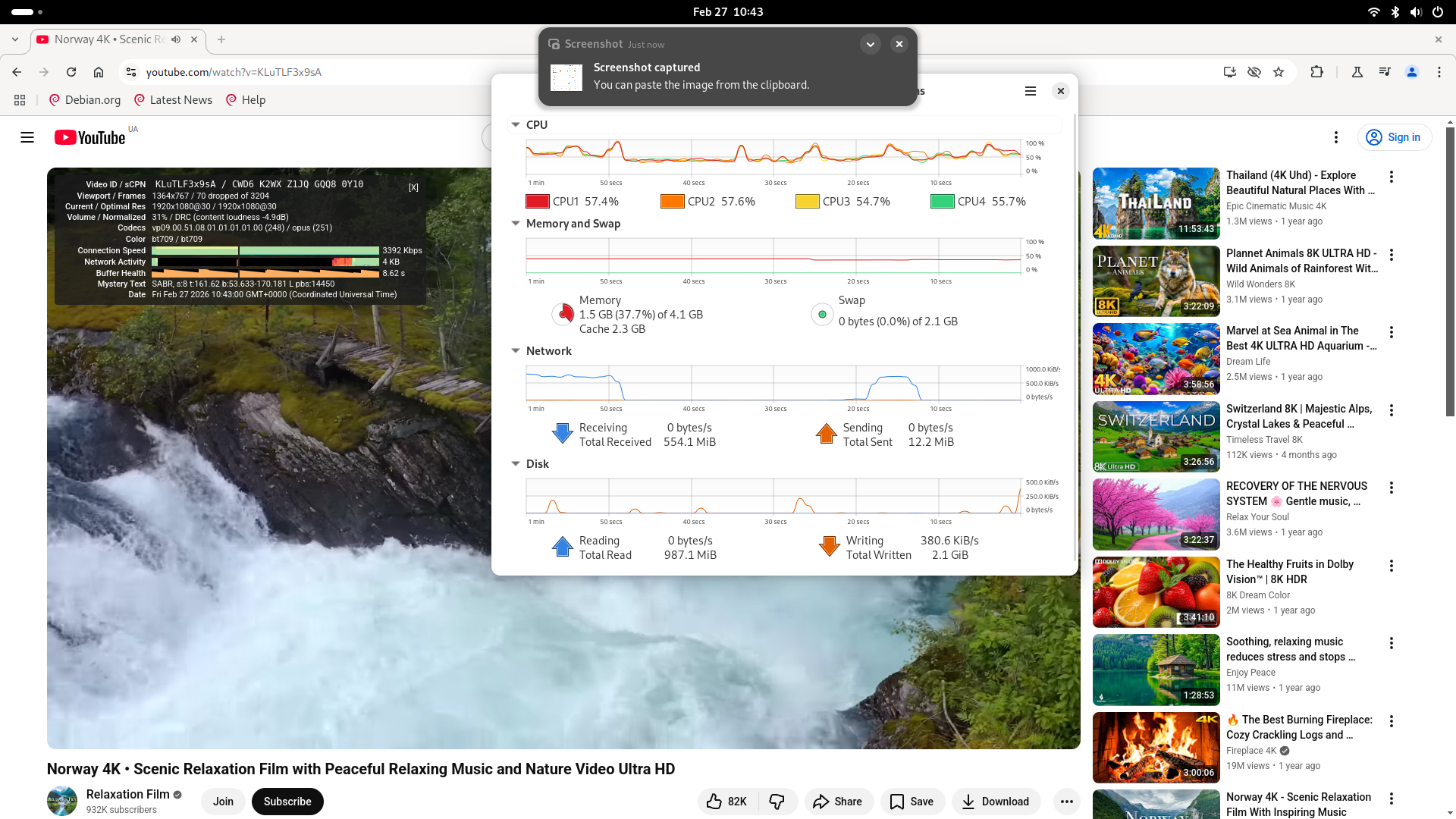
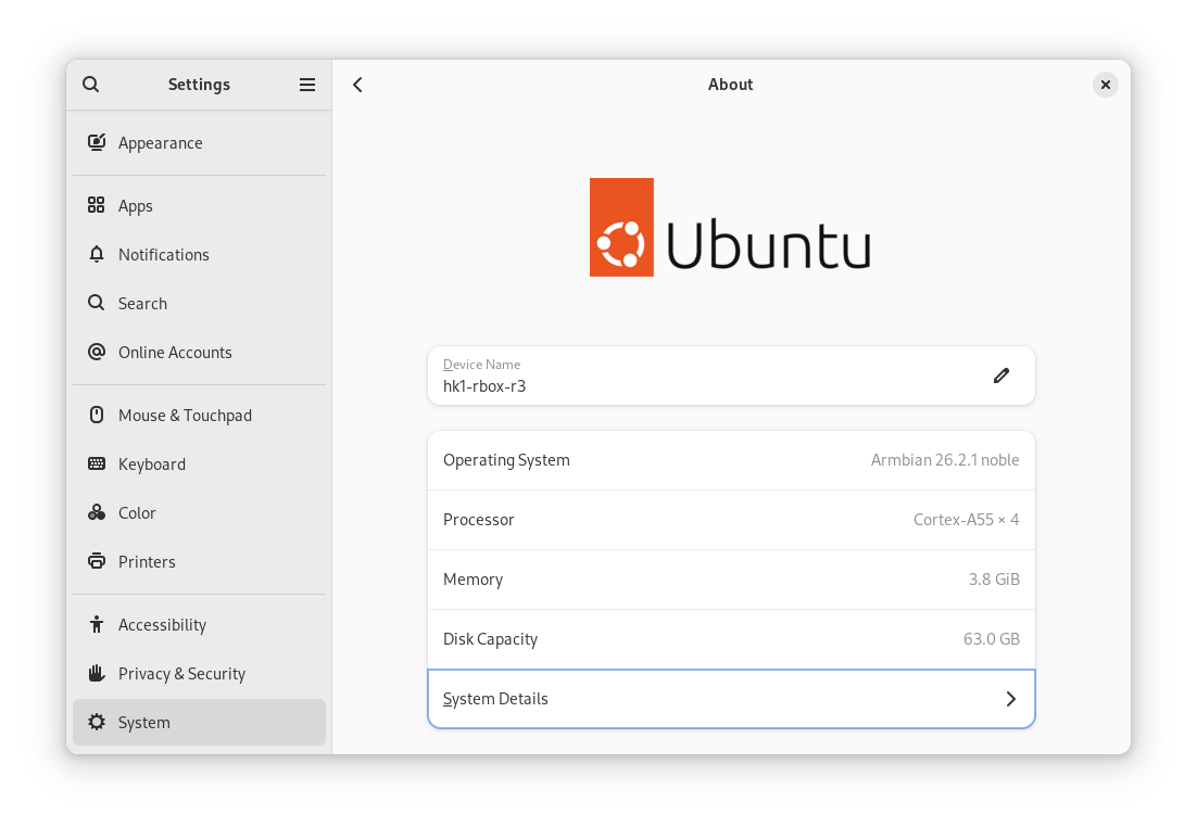
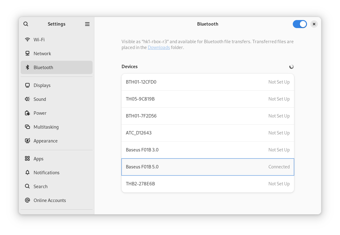
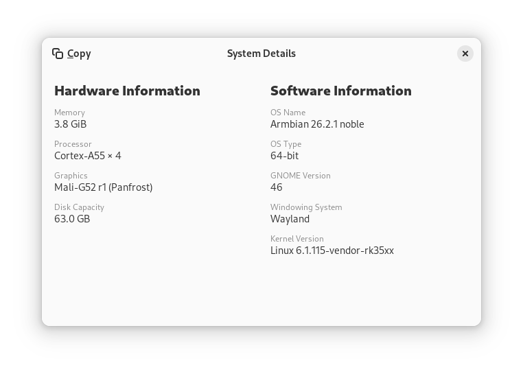
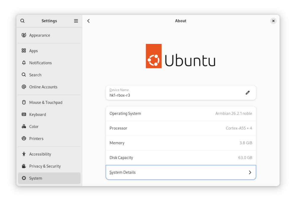
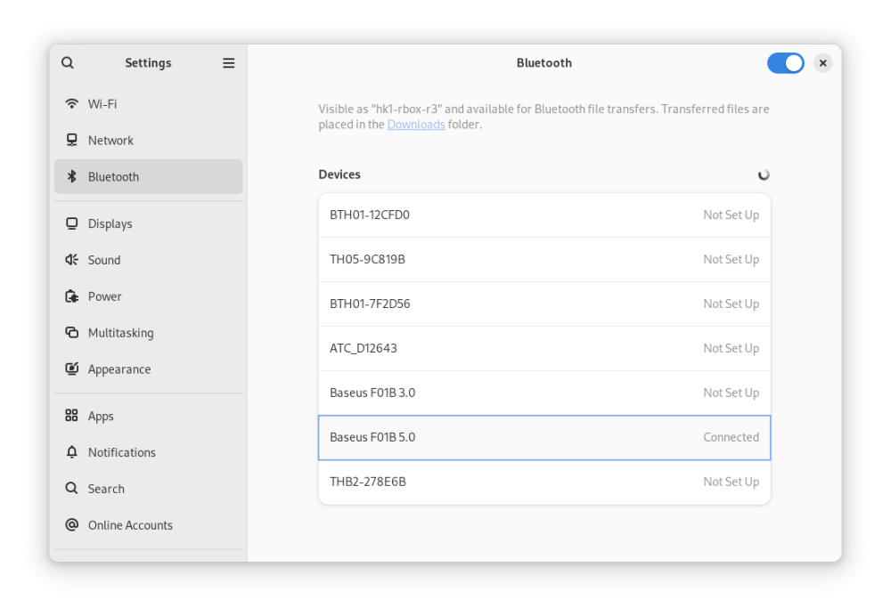
Here are the modified latest official Armbian-supported images for Radxa Zero 3W/3E. Everything works for me, including hardware-accelerated YouTube playback in Chromium (however, with a caveat): Armbian_26.2.1_hk1-rbox-r3_trixie_vendor_6.1.115_minimal.img.xz Armbian_26.2.1_hk1-rbox-r3_noble_vendor_6.1.115_gnome_desktop.img.xz MD5: 28654e87a39ac3e0b2bec4ce4211f5ca *Armbian_26.2.1_hk1-rbox-r3_noble_vendor_6.1.115_gnome_desktop.img.xz ce74829c43c6d27b02bdf314580c4dc4 *Armbian_26.2.1_hk1-rbox-r3_trixie_vendor_6.1.115_minimal.img.xz What you MUST do after installing Armbian: Freeze auto-updates for the bootloader and DTB (kernel updates are OK, except for these two packages since we use a different bootloader, not for Radxa Zero 3): sudo apt-mark hold linux-u-boot-radxa-zero3-vendor linux-dtb-vendor-rk35xx Install dependencies for hardware-accelerated playback Youtube in Chromium: sudo apt update sudo apt install chromium-codecs-ffmpeg-extra ffmpeg In Chromium, install the enhanced-h264ify extension. Then, in the extension's options, leave only AV1 disabled (i.e., enable VP8 and VP9). Screenshots: Instructions on how to modify any Armbian image yourself: Source: 4PDA
-
Wake on lan (WOL) is not working on orange pi 5 plus
Deoptim replied to dma's topic in Orange Pi 5 Plus
Here are fix. -
Continuing the tradition (1, 2) of micro-optimizations for single-board computers that come into my hands. This time I optimized or rather fixed the wake-up function via USB/WoL/WWoL on the Orange Pi 5 Plus. Also got the WiFi adapter RTW8852BE/RTW8852CE working (at least those are the ones I tested). I tested exclusively on the Vendor 6.1.x kernel since the main wake-up features via USB/PCIE/GPIO1-GPIO4 only work in it. I don't currently have the ability to test the new current kernel and I doubt that Power Management will work fully there. Armbian for Orange Pi 5 Plus from the official website, Vendor kernel (kernel 6.1.115-vendor-rk35xx), what does NOT work by default: 1. No WiFi modules that insert into the PCI-E M.2 socket E-Key work - fixed in dts below 2. Wake-up from USB (mouse/keyboard/even Bluetooth dongle) doesn't work - fixed in dts below 3. WoL via Ethernet (on two ports) - fixed in dts below I also conducted power consumption measurements in all these wake-up modes. Let's start with Ethernet ports (WoL won't work by default due to incomplete dts profile). You need to create an overlay file, links I've attached it to this message. To apply this overlay, you need to copy it somewhere on the single-board computer and execute the command: cd <path to rk3588-orangepi-5-plus-Wakeup-GPIO-RTC-USB-WoL-fixes.dts> sudo armbian-add-overlay rk3588-orangepi-5-plus-Wakeup-GPIO-RTC-USB-WoL-fixes.dts Reboot. (if it doesn't boot at all with it or something doesn't work, you can remove these changes from the /boot/overlay-user/ folder) Wake-up Timer Test: sudo sh -c "echo 0 > /sys/class/rtc/rtc0/wakealarm" sudo sh -c "echo `date '+%s' -d '+ 1 minutes'` > /sys/class/rtc/rtc0/wakealarm" sudo systemctl suspend (here we set wake-up in 1 minute from current time, you can choose seconds/minutes/hours and so on, maybe even days - haven't tested. Installing a battery on RTC is not necessary, Type-C power is sufficient) Power Consumption: Testing was performed on Imax B6 Evo / OWON HDS242S. Please note, power consumption of m.2 SSD, SD-card, eMMC is not accounted for here (ideally they should be powered off in sleep mode), but USB devices were not used, bare single-board computer was tested, each module will have its own consumption, especially USB-connected devices, add your values to the sleep mode consumption. Wake-up only via GPIO0 (this includes power button), RTC In this power-saving mode only the rk3588-orangepi-5-plus-Wakeup-GPIO0-RTC-only-fixes.dts profile is used, keep this in mind, it's not compatible with other dts, you need to choose only one option. I got these values: sudo shutdown -h now | 5.4V | 0.005W | 0.001A sudo systemctl suspend | 5.4V | 0.14W | 0.027A Wake-up via GPIO0, GPIO1-4, RTC, USB, WoL In this power-saving mode only the rk3588-orangepi-5-plus-Wakeup-GPIO-RTC-USB-WoL-fixes.dts profile is used, keep this in mind, it's not compatible with other dts, you need to choose only one option. sudo systemctl suspend | 5.4V | 0.25W | 0.046A RTL8125B (eth0 or eth1, can even be both): sudo ethtool -s eth0 wol g && sudo systemctl suspend | 5.4V | 0.33W | 0,061A RTW8852BE (external rtw8852be driver (rtw89 doesn't support WWoL for RTW8852BE in vendor 6.1 kernel)): sudo iw phy0 wowlan enable any && sudo systemctl suspend | 5.4V | 0.30W | 0,055A RTW8852CE (built-in rtw89 driver in the build): sudo iw phy0 wowlan enable magic-packet && sudo systemctl suspend | 5.4V | 0.27W | 0,051A (I want to note that the Ethernet ports on Orange Pi 5 Plus in WoL mode don't light up and don't show link activity, you can only find out if the link is working on the router or on the device to which the single-board computer is connected. In magic-packet standby mode the link switches to 10Mbit and for example on the router loses the assigned IP address, you can find out if the device is alive only by ARP scanning on the router itself or by the link light indication on the router itself. The same applies to WWoL (WiFi) - only on the router or device to which the single-board computer is connected can you check in active clients mode or ARP scan for the presence of MAC address) My Armbian build from the official website on Vendor 6.1 kernel where rtw89 (WiFi) modules are already compiled and pre-installed in the kernel has a peculiarity that this driver supports WWoL function only for RTW8852CE - this is a slightly different chip than the official proprietary WiFi module for Orange Pi 5 Plus which uses RTW8852BE. For WWoL to work on RTW8852BE you need to install a third-party driver, for example I recommend from this source. How to use WoL, WWoL: For wired network use ip and ethtool utilities, for wireless network iw. WoL over LAN WWoL over WiFi External Drivers: For RTW8852BE/RTW8852CE and others there are fairly recent drivers (at the time of writing this manual), here's a brief instruction on how to install them on Orange Pi 5 Plus. Issues: File: rk3588-orangepi-5-plus-Wakeup-GPIO-RTC-USB-WoL-fixes.dts File: rk3588-orangepi-5-plus-Wakeup-GPIO0-RTC-only-fixes.dts Original Link 4PDA
-
Vontar KK MAX / HK1 RBOX R2 / R3 - RK3566 4GB/32GB(or 64GB)
Deoptim replied to Deoptim's topic in Rockchip CPU Boxes
Continuing the story. Or 4pda (Russian). -
Efforts to develop firmware for H96 MAX V56 RK3566 8G/64G
Deoptim replied to Hqnicolas's topic in Rockchip CPU Boxes
Continuing on the topic of replacing the LPDDR4 memory chip. Here is a successful experience of replacement. -
Efforts to develop firmware for H96 MAX M9 RK3576 TV Box 8G/128G
Deoptim replied to Hqnicolas's topic in Rockchip CPU Boxes
In dts RK809 node for that device needed configuration for SD card 3v3 regulator and 1v8 regulator - than theoretically SD card will work fine. -
Efforts to develop firmware for H96 MAX V56 RK3566 8G/64G
Deoptim replied to Hqnicolas's topic in Rockchip CPU Boxes
The chip on LCSC ~6$ is 8gbit (or 1GByte). The chip on Taobao ~15$ is 64gbit (8GByte) but has 2 ranks (2 CS) Dual-Rank must be supported in your hardware, e.g. there must be tracks and pads under LPDDR for both A and B channel: CS0_A, CS0_B and CS1_A, CS1_B same for data lines DQ_0-15_A and DQ_0-15_B etc.... I bought it for my Rock 3A (2GB), If I bought this SBC for 25$ (34$ on Taobao or 49$ on AliExpress), then plus this memory chip +15$(not including shipping) comes out to 40$ for my case. Also I have the skills of soldering and repairing with a soldering air station - this is also important, by the way I bought a stencil for bga200 + solder paste (or balls for bga rebolling) just in case I have to re-solder. -
Efforts to develop firmware for H96 MAX V56 RK3566 8G/64G
Deoptim replied to Hqnicolas's topic in Rockchip CPU Boxes
I bought a similar chip for ~15$ on Taobao: https://item.taobao.com/item.htm?id=828400739165 But it is profitable to buy on Taobao if let's say order something else say in the amount of 1kg - that the delivery (about 20$, of course, shipping is only through an intermediary) paid for itself. -
Efforts to develop firmware for H96 MAX V56 RK3566 8G/64G
Deoptim replied to Hqnicolas's topic in Rockchip CPU Boxes
What about "Ubuntu 24.04 LTS with Rockchip Linux 6.1" anyone try to launch ubuntu-24.04-preinstalled-desktop-arm64-orangepi-3b.img.xz or ubuntu-24.04-preinstalled-desktop-arm64-radxa-zero3.img.xz image? I tried launch images on hk1-rbox-r3 TVBox with modified dtb, but no luck. UART Boot log hungs on: ... ... systemd[1]: Started systemd-journald.service - Journal Service. -
Efforts to develop firmware for H96 MAX V56 RK3566 8G/64G
Deoptim replied to Hqnicolas's topic in Rockchip CPU Boxes
For chromium browser you need to create udev node: https://github.com/saiarcot895/chromium-ubuntu-build/issues/65#issuecomment-1793738401 -
Efforts to develop firmware for Vontar KK Max 8gb/128gb"
Deoptim replied to gersones's topic in Rockchip CPU Boxes
Hello. Here are in this thread I post Armbian 24.5.0 Bookworm images that should be compatible with Vontar KK MAX. Also added remarks about dualboot for ex. if we want to make untouched Android and at the same time boot only from SD-Card. Also added recommendations for installation on eMMC. -
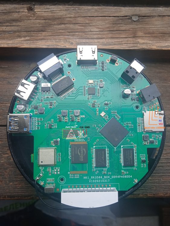
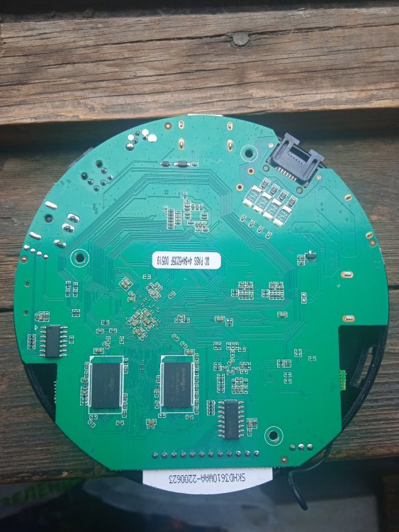
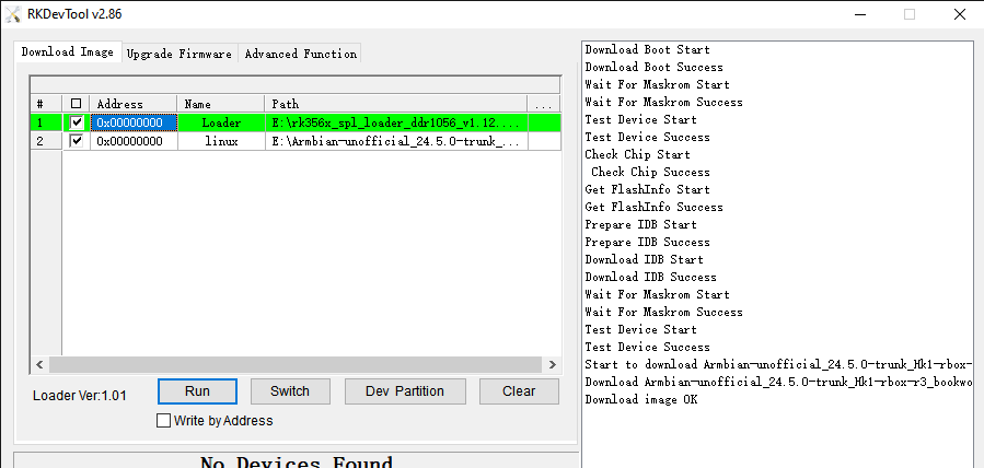
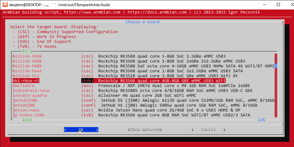
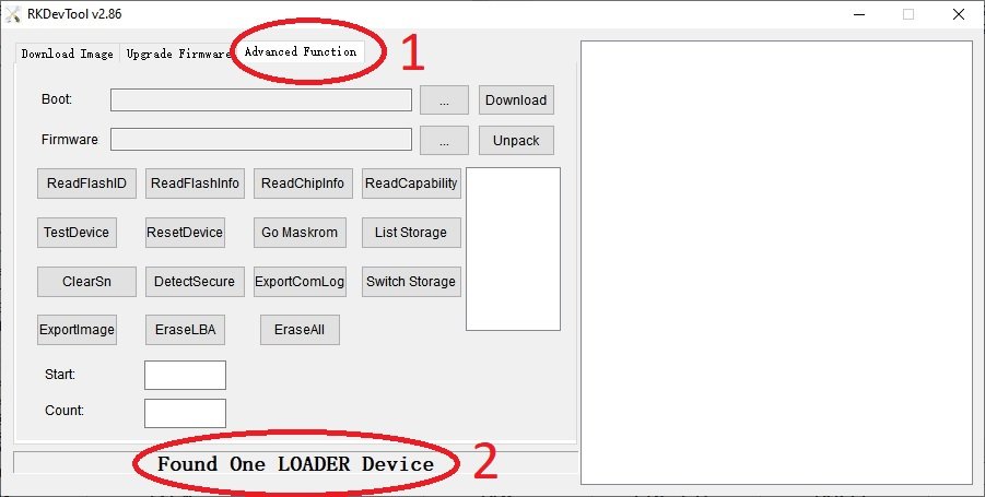
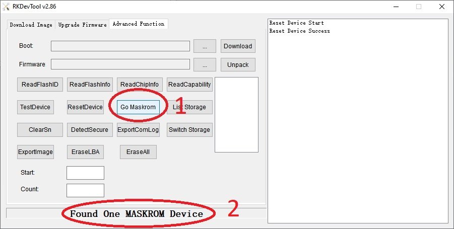
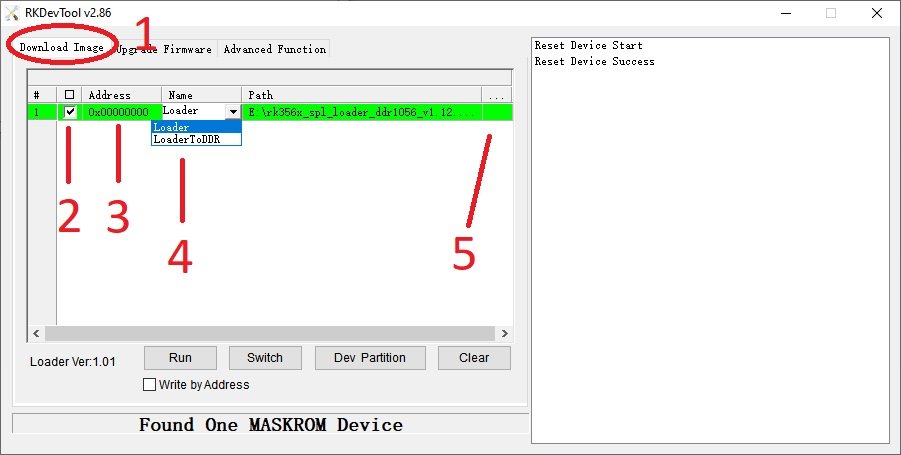
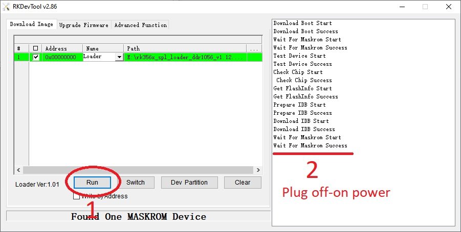
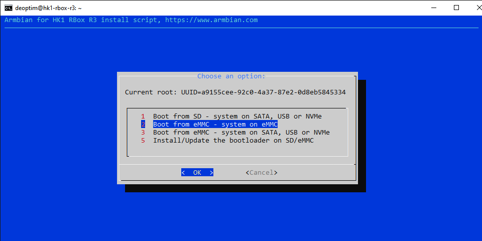
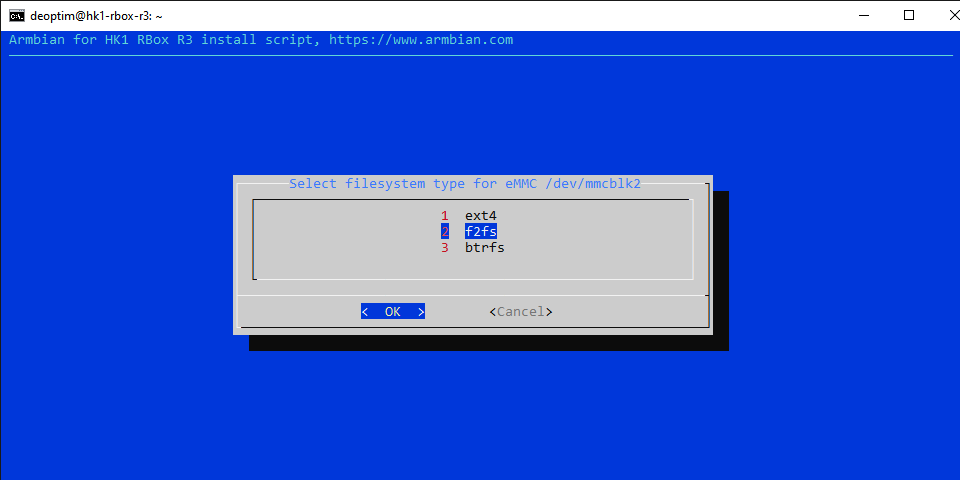
Armbian 24.5.0 Bookworm images (linux-6.1/linux-6.6) for TVBoxes: Vontar KK MAX / HK1 RBOX R2 / HK1 RBOX R3 (the same dts/dtb should work for these TVBoxes) Here is a dts and dtb files, working reworked for mainline: hk1-rbox-r3-profile-kernel-6.1-6.6.zip (original dts and dtb from TVBox rk-kernel-orig.zip) Checked the following: HDMI - works (need to check hot plugging) HDMI sound - works USB 2.0 - works USB 3.0 - works SPDIF - should work (I cannot to check) SD-Card booting and detection - works eMMC install on it (/sbin/nand-sata-install) and detection - works RKDevTool installing and loading images on/from eMMC - works GPU (bugs/frizzes on mainline are not canceled) - works Hardware video acceleration(except for browsers) - works Dualboot if you flash new bootloader (SD-Card boot high priority) - works Here are the compiled Armbian images (Bookworm only) with integrated dtb: https://www.mediafire.com/file/4dwf7ce922x7obq/Armbian-unofficial_24.5.0-trunk_Hk1-rbox-r3_bookworm_current_6.1.87_cinnamon_desktop.img.xz/file https://www.mediafire.com/file/fjwtxb5gjzip341/Armbian-unofficial_24.5.0-trunk_Hk1-rbox-r3_bookworm_current_6.1.87_minimal.img.xz/file https://www.mediafire.com/file/iuz4uijgjh5ry1r/Armbian-unofficial_24.5.0-trunk_Hk1-rbox-r3_bookworm_current_6.6.28_cinnamon_desktop.img.xz/file https://www.mediafire.com/file/kofyqabr5k6qxm8/Armbian-unofficial_24.5.0-trunk_Hk1-rbox-r3_bookworm_current_6.6.28_minimal.img.xz/file The one of this box itself is HK1 RBOX R3, the photo shows the pins for short to go to the Maskrom bootloader and UART pins: A working bootloader(supports dualboot) on this hardware for RKDevTool tool just in case: Loader.zip Please note that RKDevTool flashing utility only needs to flash the .img file with the bootloader, i.e. you need to unpack the .xz archive somewhere first (for ex. you can use 7-zip). -- Recommendations for installation on eMMC ---------------------------------------------------- For those who want to build Armbian themselves, here are the instructions: UPD: Added to images "f2fs-tools" package, added loader to support dualboot without touching the original Android(or other OS) image on eMMC - priority is given to SD-Card. Boot will be from SD-Card if there is on boot partition exist folder and file \boot.scr or extlinux\extlinux.conf - uboot(both: original Android and compiled for Armbian) searches for this path and file if it found this file, it will load from device which contains this file. mmc1(SD-Card) - first, mmc0(eMMC) - second. For correct priority loading it is necessary to replace the main bootloader which is in the archive Loader.zip - if you have an Android it is enough to flash only this bootloader as Loader at 0x0 offset using RKDevTool utility, the rest of the eMMC part should not be touched if the OS and settings we need are there. U-boot on eMMC must be original or Armbian and preinstalled at offset 0x4000. Instructions: (remember, uboot must be on eMMC (even the original Android or Armbian, i.e. if you erase the eMMC - the boot will not work) and this is relevant if you have installed the original MiniLoaderAll.bin, which does not support booting from SD-Card, but only from eMMC. Some TVBoxes may already have a bootloader that supports SD-card booting.). Feel free to test...
-
deleted - offtopic
-
@JRD McLAREN Did you get banned on AliExpress? RTL8189FTV priced under $2 with free shipping.
-
Usage ffmpeg with motioneye on Allwinner H3 board ( 6.1.63-current-sunxi kernel ) https://4pda-to.translate.goog/forum/index.php?showtopic=750921&st=10260&_x_tr_sl=ru&_x_tr_tl=en&_x_tr_pto=wapp#entry128032933
-
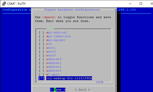
Instruction on how to use wireless WoL (Wake on LAN) using RTL8189FS example in Armbian 23.x Bookworm (This wireless WIFI adapter is installed in Oprange Pi Lite/Oprange Pi Plus(2E)/Orange Pi Zero Plus/Oprange Pi PC Plus/Oprange Pi 2/etc...) 1. First of all we need to change the device tree configuration file dts file for our single board. The point is that for most WIFI drivers for SDIO interface there is a normal configuration of single board wake-up via interrupt and therefore there is no need to go into dts. In the driver for RTL8189FS (aka RTL8189FTV) there is NO such feature as "host-wake" interrupt and we will have to make small changes to wake up the single board when Magic packet (WoL) is detected through the "gpio-keys" button module. The same method will most likely work for the related RTL8189ES (aka RTL8189ETV) adapter, but keep in mind that here you will most likely need other settings in the dts file, since the gpios (for wifi_rst and wifi_wake) for your single-board adapter will be under a different number. 2 The second step is to compile and install a new driver for RTL8189FS with WoL function enabled, I will do it on the single board itself. You can also do cross compilation (do it on your computer). 3. How to use WoL. 4. Additionally. wol-wakeup-for-rtl8189fs.dts.txt QuickStartGuideforWOW.399483868.pdf Link to original source
-
How to install Home Assistant Supervised on Armbian 23.02 Jammy (plus minus, but quite installed on the previous release of Armbian, this is based on Debian 10) Performed exclusively without a graphical interface, from the console. Works stably on Orange Pi Lite , including a connected Bluetooth dongle via USB and sensors to it. 1. The first installation of Armbian and the subsequent creation of a user and passwords, the next is required to install all updates via sudo apt update && sudo apt upgrade -y . Then you need to install the Firmware update through the armbian-config ->System utility as in the screenshot. (When prompted for reboot - reboot the system.) Separately for owners of Orange Pi Lite: 2. Next, follow the instructions https://github.com/home-assistant/supervised-installer up to "Step 4" If we continue to install "Step 4", it will not allow installation and will write in red letters that the current system is not supported and the system must be Debian 11. 3. In this case, it is necessary during the installation, to replace one variable in the system in the /etc/os-release file . It is necessary to replace in this file PRETTY_NAME="Armbian 23.02.2 Jammy" on PRETTY_NAME="Debian GNU/Linux 11 (bullseye)" (from sudo rights, eg "sudo nano /etc/os-release" editor) 4. And continue with "Step 4" in the instructions. In the installation type selection window, select "qemuarm" for armv7, this is important . 5. After installation, the services for deploying the docker container will immediately load automatically. Note that it took me ~15 minutes ! The progress of the deployment can be monitored indirectly in htop (you can open a window in parallel in another ssh terminal). 6. For autoload, you need to activate autoload services: sudo systemctl enable hassio-apparmor.service sudo systemctl enable hassio-supervisor.service For Bluetooth integration to work, you must install "sudo apt-get -y install bluez" into the system beforehand. Additionally: 1. The main file(s) of the Home Assistant configuration ( for ex. like configuration.yaml ) on this system will be located along the path /usr/share/hassio/homeassistant/ , in the same folder, if necessary, you need to throw custom_components . 2. If you want to use /dev/ttyUSB0 (or HC-05 ( /dev/rfcomm0 ) for example after auto connect via bluetoothctl ) on your Armbian and in conjunction with Home Assistant, then you need to add rights to your user: sudo gpasswd --add <user> dialout sudo newgrp dialout (Note that the brackets <> should be your data instead. Also, if you will use i2c in the same way as dialout, write i2c ) Working with GPIO from userspace in Armbian Option 1 (classic) By default, the OS does not allow gpio to be controlled via sysfs (/sys/class/gpio/) to a non-root user, to fix this you need to do the following: 1. Create a gpio group: sudo groupadd gpio 2. We give our user access to the gpio group: sudo usermod -aG gpio <user> 3. Create a rule for udev when the system boots: sudo nano /etc/udev/rules.d/99-gpio.rules Paste in the file "/etc/udev/rules.d/99-gpio.rules" the following SUBSYSTEM=="gpio", KERNEL=="gpiochip*", GROUP="gpio", ACTION=="add", PROGRAM="/bin/sh -c 'chown root:gpio /sys/class/gpio/export /sys/class/gpio/unexport ; chmod 220 /sys/class/gpio/export /sys/class/gpio/unexport'" SUBSYSTEM=="gpio", KERNEL=="gpio*", GROUP="gpio", ACTION=="add", PROGRAM="/bin/sh -c 'chown root:gpio /sys%p/active_low /sys%p/direction /sys%p/edge /sys%p/value ; chmod 660 /sys%p/active_low /sys%p/direction /sys%p/edge /sys%p/value'" 4. Reboot: sudo reboot For Allwinner H3 gpio, the following picture corresponds to the connector: (Where BCM corresponds to the GPIO number in Armbian, more details can be found here ) It should now be possible to change (monitor) all these gpios non-root , i.e. when we do for example "echo 6 > /sys/class/gpio/export", then it will use the physical 7 pin of the connector as the folder "/sys/class/gpio/gpio6" etc... Option 2 (recommended) A new option without any sysfs is to use the built-in Armbian tools like gpiodetect, gpiofind, gpioget, gpioinfo, gpiomon, gpioset (Help). Additionally: For Home Assistant, in addition to the classic way, it is much easier to do the second option, for example: This is a binary_sensor in the form of a pressing to the button (input😞 binary_sensor: - platform: command_line name: external_button_state command: "gpioget gpiochip0 6" payload_off: "0" payload_on: "1" scan_interval: 0.250 (same 7 pin on connector as GPIO6 on Armbian , scan_interval set to 0.250 in seconds - means 250ms) Or a switch like slide switch 😀 (output) : switch: - platform: command_line switches: something_change_value: friendly_name: Test Switch pulling GPIO output command_on: gpioset -B pull-up gpiochip0 64=1 command_off: gpioset -B pull-down gpiochip0 64=0 command_state: test $(gpioget gpiochip0 64) = 1 (where pin 19 is used on the connector that is GPIO64 on Armbian as an output signal, 0=low[0V] 1=high[3.3V], the test command tests the already set switch value and changes it almost in real time - this is necessary if let's say we have someone else who controls the signal, or it changes dynamically, or in general, another pin can be set for the status) ----------------- That's all, successful projects for you! Original link