
Stephen Graf
-
Posts
161 -
Joined
-
Last visited
Content Type
Forums
Store
Crowdfunding
Applications
Events
Raffles
Community Map
Everything posted by Stephen Graf
-
I have been able to create an overlay for spidev, copying the Zunlong overlays. An overlay is necessary to set disabled to okay ie to enable the device.
-
@pixdrift You will need a connection to the console uart to catch the log of the overlays. It all happens at boot time before the OS is started. On the system as root go to armbian-config and then System and Hardware. enable (space) all of the items offered. Then save, back and reboot. Watch the output of the console. U-Boot 2024.01-rc5-armbian (Dec 31 2023 - 01:13:07 +0000) Allwinner Technology CPU: Allwinner H616 (SUN50I) Model: OrangePi Zero3 DRAM: 1 GiB Core: 57 devices, 25 uclasses, devicetree: separate WDT: Not starting watchdog@30090a0 MMC: mmc@4020000: 0 Loading Environment from FAT... Unable to use mmc 0:1... In: serial@5000000 Out: serial@5000000 Err: serial@5000000 Allwinner mUSB OTG (Peripheral) Net: Unsupported value 13, using default (13) Unsupported value 13, using default (13) eth0: ethernet@5020000using musb-hdrc, OUT ep1out IN ep1in STATUS ep2in MAC de:ad:be:ef:00:01 HOST MAC de:ad:be:ef:00:00 RNDIS ready , eth1: usb_ether starting USB... Bus usb@5200000: USB EHCI 1.00 Bus usb@5200400: USB OHCI 1.0 scanning bus usb@5200000 for devices... 1 USB Device(s) found scanning bus usb@5200400 for devices... 1 USB Device(s) found scanning usb for storage devices... 0 Storage Device(s) found Autoboot in 1 seconds, press <Space> to stop switch to partitions #0, OK mmc0 is current device Scanning mmc 0:1... Found U-Boot script /boot/boot.scr 3259 bytes read in 2 ms (1.6 MiB/s) ## Executing script at 4fc00000 U-boot loaded from SD Boot script loaded from mmc 299 bytes read in 2 ms (145.5 KiB/s) 31257 bytes read in 4 ms (7.5 MiB/s) Working FDT set to 4fa00000 268 bytes read in 3 ms (86.9 KiB/s) Applying kernel provided DT overlay sun50i-h616-ir.dtbo 512 bytes read in 3 ms (166 KiB/s) Applying kernel provided DT overlay sun50i-h616-light.dtbo failed on fdt_overlay_apply(): FDT_ERR_NOTFOUND 339 bytes read in 3 ms (110.4 KiB/s) Applying kernel provided DT overlay sun50i-h616-mcp2515.dtbo
-
Test on orangepi3 of the overlays provided by armbian-config. Not one worked! Working FDT set to 4fa00000 268 bytes read in 3 ms (86.9 KiB/s) Applying kernel provided DT overlay sun50i-h616-ir.dtbo 512 bytes read in 3 ms (166 KiB/s) Applying kernel provided DT overlay sun50i-h616-light.dtbo failed on fdt_overlay_apply(): FDT_ERR_NOTFOUND 339 bytes read in 3 ms (110.4 KiB/s) Applying kernel provided DT overlay sun50i-h616-mcp2515.dtbo failed on fdt_overlay_apply(): FDT_ERR_BADMAGIC base fdt does not have a /__symbols__ node make sure you've compiled with -@ 661 bytes read in 3 ms (214.8 KiB/s) Applying kernel provided DT overlay sun50i-h616-spidev0_0.dtbo failed on fdt_overlay_apply(): FDT_ERR_BADMAGIC base fdt does not have a /__symbols__ node make sure you've compiled with -@ 661 bytes read in 3 ms (214.8 KiB/s) Applying kernel provided DT overlay sun50i-h616-spidev1_0.dtbo failed on fdt_overlay_apply(): FDT_ERR_BADMAGIC base fdt does not have a /__symbols__ node make sure you've compiled with -@ 661 bytes read in 3 ms (214.8 KiB/s) Applying kernel provided DT overlay sun50i-h616-spidev1_1.dtbo failed on fdt_overlay_apply(): FDT_ERR_BADMAGIC base fdt does not have a /__symbols__ node make sure you've compiled with -@ 661 bytes read in 3 ms (214.8 KiB/s) Applying kernel provided DT overlay sun50i-h616-spidev1_2.dtbo failed on fdt_overlay_apply(): FDT_ERR_BADMAGIC base fdt does not have a /__symbols__ node make sure you've compiled with -@ 808 bytes read in 3 ms (262.7 KiB/s) Applying kernel provided DT overlay sun50i-h616-spi-spidev.dtbo failed on fdt_overlay_apply(): FDT_ERR_BADMAGIC base fdt does not have a /__symbols__ node make sure you've compiled with -@ 616 bytes read in 3 ms (200.2 KiB/s) Applying kernel provided DT overlay sun50i-h616-tft35_spi.dtbo failed on fdt_overlay_apply(): FDT_ERR_BADMAGIC base fdt does not have a /__symbols__ node make sure you've compiled with -@ 272 bytes read in 3 ms (87.9 KiB/s) Applying kernel provided DT overlay sun50i-h616-ws2812.dtbo failed on fdt_overlay_apply(): FDT_ERR_BADMAGIC base fdt does not have a /__symbols__ node make sure you've compiled with -@ Error applying DT overlays, restoring original DT 31257 bytes read in 4 ms (7.5 MiB/s)
-
The situation with the overlays is more confusing than I originally anticipated. I assumed that the zero2 overlays would have been in good working order. I should know better than to assume anything! Would someone with an orangepizero2 please test the overlay function to see what works and does not. Use armbian-config -> System -> Hardware and turn on all options. Reboot and check the console boot log to see which overlays load or fail. It looks like the bigtreetech-cb1board created the overlay for sun50i-h616 (/kernel/archive/sunxi-6.7/patches.armbian/arm64-dts-overlay-sun50i-h616-bigtreetech-cb1.patch). However not all SBCs that use the h616 SOC implement the same features. The current sun50i-h616 overlays have implementations for ws8212, tft3, mcp and light, none of which exist on orangepizero2/3. The spi overlays might work as well as the ir. There is no overlay to enable i2c3 or add host function to usbotg. New SBCs that use the h618 SOC will probably implement different features than the zero2/3. The zero2 (h616) and the zero3 (h618) implement the same i/o features. My current thoughts are to implement a new set of overlays for the orangepizero2/3, which have identical i/o. Then both boards then need to be pointed to the new overlays with an overlay_prefix in the board config. I would start with the overlays from the Zunlong distribution for orangepizero3. I would appreciate feedback before I go charging off in the wrong direction (again).
-
I have a zero3 with 1G ram. I just stuck some small heats sinks on the cpu and mem. A stress test and results are included below. Before Armbian was viable I compiled the Linux kernel on this system using the Zunlong image. It ran for a couple of hours with all 4 cpus at 100%. The temperature stayed constant at about 65, but it worked without a problem. sysadmin@orangepizero3:~$ sudo stress --cpu 4 --io 4 -m 4 --vm-bytes 256M -t 300 stress: info: [2144] dispatching hogs: 4 cpu, 4 io, 4 vm, 0 hdd stress: info: [2144] successful run completed in 301s 12:07:25 480 MHz 3.60 0% 0% 0% 0% 0% 0% 41.3 °C 0/5 12:07:31 480 MHz 3.39 0% 0% 0% 0% 0% 0% 41.3 °C 0/5 12:07:36 1512 MHz 3.20 22% 15% 7% 0% 0% 0% 43.8 °C 0/5 12:07:41 1512 MHz 4.07 100% 64% 35% 0% 0% 0% 48.0 °C 0/5 12:07:46 1512 MHz 4.78 100% 64% 35% 0% 0% 0% 48.7 °C 0/5 12:07:51 1512 MHz 5.44 100% 64% 35% 0% 0% 0% 49.3 °C 0/5 ... 12:12:09 1512 MHz 13.22 100% 66% 33% 0% 0% 0% 56.7 °C 0/5 12:12:14 1512 MHz 13.20 100% 64% 35% 0% 0% 0% 56.5 °C 0/5 12:12:19 1512 MHz 13.18 100% 65% 34% 0% 0% 0% 56.4 °C 0/5 Time CPU load %cpu %sys %usr %nice %io %irq Tcpu C.St. 12:12:25 1512 MHz 13.17 100% 64% 35% 0% 0% 0% 57.0 °C 0/5 12:12:30 1512 MHz 13.16 100% 65% 34% 0% 0% 0% 56.8 °C 0/5 12:12:35 1512 MHz 13.14 96% 62% 30% 0% 3% 0% 56.8 °C 0/5 12:12:40 480 MHz 12.17 0% 0% 0% 0% 0% 0% 51.0 °C 0/5 12:12:45 480 MHz 11.28 0% 0% 0% 0% 0% 0% 49.9 °C 0/5 12:12:50 480 MHz 10.45 0% 0% 0% 0% 0% 0% 49.1 °C 0/5 12:12:55 480 MHz 9.69 0% 0% 0% 0% 0% 0% 48.4 °C 0/5 ... 12:56:56 480 MHz 1.00 0% 0% 0% 0% 0% 0% 39.1 °C 0/5 12:57:01 480 MHz 1.08 0% 0% 0% 0% 0% 0% 39.5 °C 0/5 12:57:06 480 MHz 1.07 0% 0% 0% 0% 0% 0% 39.3 °C 0/5 12:57:11 480 MHz 1.06 0% 0% 0% 0% 0% 0% 39.2 °C 0/5
-
@pixdrift Since @Gunjan Gupta is busy with another project he asked me to prepare a PR for the following patch. I have never done this and so I am asking you to help with it. It makes sense to point to the h616 overlays as the zero3 and zero2 are common for the items that would normally go into the overlays. I have been using the proposed change and it makes the fixup.scr work on boot and allows armbian-config > System > Hardware to work and load overlays on boot. diff --git a/config/boards/orangepizero3.wip b/config/boards/orangepizero3.wip index 18bcae79d..642eb216f 100644 --- a/config/boards/orangepizero3.wip +++ b/config/boards/orangepizero3.wip @@ -3,6 +3,7 @@ BOARD_NAME="Orange Pi Zero3" BOARDFAMILY="sun50iw9" BOARD_MAINTAINER="viraniac" BOOTCONFIG="orangepi_zero3_defconfig" +OVERLAY_PREFIX=sun50i-h616 BOOT_LOGO="desktop" KERNEL_TARGET="current,edge" FORCE_BOOTSCRIPT_UPDATE="yes" (When I first started working, the concept of patching and PR consisted of shuffling a deck of IBM punched cards!)
-
@Gunjan Gupta, @pixdrift Re zero2w The hardware output on the zero2 is very different from the zero2/3. The zero2w has a 40 pin header and a 24 pin connector while the zero2/3 have a 26 pin and 13 pin header. The zero2w exposes - twi0, 1, 2 (i2c) - uart0, 2, 3, 4 - spi1 - pm1, 2, 4 - usb2, 3 and a bit more The zero2/3 expose - i2c3 (twi) - spi1 - uart5 - usb2, 3 and a bit more. Some of the pin definitions are common, but many are not. Also the zero2w has multiple definitions for some pins.
-
I think the overlay files for zero2 and zero3 can be the same as the hardware layout is identical. Zero2w is different. I have put together and tested 3 overlay files, - enable i2c3 - enable spi1 and create spidev - change usbotg to host I could use the i2c3 and spi1 overlays to fix the PH5 duplication if it will not be done in sun50i-h616.dtsi. Usb2 and 3 are already enabled and work without further changes. I am still looking into uart5 to determine what is required. Ir is another item to look at. Then there is sound which has output on the header. But since sound is not yet working that will have to wait. All these overlays currently exist in the Zunlong image. After @Gunjan Gupta showed me how to build an overlay I am now able to reverse engineer the Zunlong dtbos and create dts/dtbo for Armbian.
-
The sun50-h616.dtsi will not work for zero2w either. Zero2 and zero3 i/o layout are the same but zero2w is different. Dtb is all about describing the hardware and so zero2w will need something different.
-
PH5 pin assignment conflict. The sun50i-h616.dtsi has PH5 in 2 pin assignments. i2c3_ph_pins: i2c3-ph-pins { pins = "PH4", "PH5"; function = "i2c3"; }; and /omit-if-no-ref/ spi1_cs0_pin: spi1-cs0-pin { pins = "PH5"; function = "spi1"; }; The diagrams for zero3 and zero2 both show that spi1-cs as PH9. The zero2w has a very different layout! I think patch/kernel/archive/sunxi-6.7/patches.armbian/arm64-dts-allwiner-sun50i-h616.dtsi-add-usb-ehci-ohc.patch which has changes for spi also should be modified to change spi1_cs0 pins = "PH9"; There is no reference to PH9 in the zero3 dtb.
-
@Gunjan Gupta, Would you be able move forward the following patch. I have been working on the zero3 overlays and with your help I have made some progress. But it all depends on having the overlay_prefix set. It makes sense to point to the h616 overlays as the zero3 and zero2 are common for the items that would normally go into the overlays. I have been using the proposed change and it makes the fixup.scr work on boot and allows armbian-config > System > Hardware to work and load overlays on boot diff --git a/config/boards/orangepizero3.wip b/config/boards/orangepizero3.wip index 18bcae79d..642eb216f 100644 --- a/config/boards/orangepizero3.wip +++ b/config/boards/orangepizero3.wip @@ -3,6 +3,7 @@ BOARD_NAME="Orange Pi Zero3" BOARDFAMILY="sun50iw9" BOARD_MAINTAINER="viraniac" BOOTCONFIG="orangepi_zero3_defconfig" +OVERLAY_PREFIX=sun50i-h616 BOOT_LOGO="desktop" KERNEL_TARGET="current,edge" FORCE_BOOTSCRIPT_UPDATE="yes"
-
@Serby Thank you for the advice. With my limited experience with dtbo I have put together the following with not much success. If you could help it would be appreciated. The overlay compiles with warnings. It loads on boot but no spidev is generated in /dev. I am guessing at the compatible line. Original dtb: spi@5010000 { compatible = "allwinner,sun50i-h616-spi\0allwinner,sun8i-h3-spi"; reg = <0x5010000 0x1000>; interrupts = <0x00 0x0c 0x04>; clocks = <0x02 0x4f 0x02 0x4d>; clock-names = "ahb\0mod"; resets = <0x02 0x1c>; pinctrl-names = "default"; pinctrl-0 = <0x1c 0x1d>; status = "okay"; #address-cells = <0x01>; #size-cells = <0x00>; phandle = <0x53>; flash@0 { #address-cells = <0x01>; #size-cells = <0x01>; compatible = "jedec,spi-nor"; reg = <0x00>; spi-max-frequency = <0x2625a00>; }; }; spi@5011000 { compatible = "allwinner,sun50i-h616-spi\0allwinner,sun8i-h3-spi"; reg = <0x5011000 0x1000>; interrupts = <0x00 0x0d 0x04>; clocks = <0x02 0x50 0x02 0x4e>; clock-names = "ahb\0mod"; resets = <0x02 0x1d>; pinctrl-names = "default"; pinctrl-0 = <0x1e>; status = "disabled"; #address-cells = <0x01>; #size-cells = <0x00>; phandle = <0x54>; }; spi0_pins = "/soc/pinctrl@300b000/spi0-pins"; spi0_cs0_pin = "/soc/pinctrl@300b000/spi0-cs0-pin"; spi1_pins = "/soc/pinctrl@300b000/spi1-pins"; spi1_cs0_pin = "/soc/pinctrl@300b000/spi1-cs0-pin"; spi0 = "/soc/spi@5010000"; spi1 = "/soc/spi@5011000"; Overlay: /dts-v1/; /plugin/; &spi1 { status = "okay"; pinctrl-names = "default"; pinctrl-0 = <&spi1_pins &spi1_cs0_pin>; spidev1_0: spidev@0 { compatible = "allwinner,sun50i-h616-spidev\0allwinner,sun8i-h3-spidev"; reg = <0>; #address-cells = <0x01>; #size-cells = <0x00>; spi-max-frequency = <0x2625a00>; status = "okay"; }; }; Compile: sysadmin@orangepizero3:/memstick/dtbo$ dtc -@ -O dtb -o sun50i-h616-spi1.dtbo sun50i-h616-spi1.dts sun50i-h616-spi1.dts:11.3-13: Warning (reg_format): /fragment@0/__overlay__/spidev@0:reg: property has invalid length (4 bytes) (#address-cells == 2, #size-cells == 1) sun50i-h616-spi1.dtbo: Warning (pci_device_reg): Failed prerequisite 'reg_format' sun50i-h616-spi1.dtbo: Warning (pci_device_bus_num): Failed prerequisite 'reg_format' sun50i-h616-spi1.dtbo: Warning (simple_bus_reg): Failed prerequisite 'reg_format' sun50i-h616-spi1.dtbo: Warning (i2c_bus_reg): Failed prerequisite 'reg_format' sun50i-h616-spi1.dtbo: Warning (spi_bus_reg): Failed prerequisite 'reg_format' sun50i-h616-spi1.dts:9.22-16.4: Warning (avoid_default_addr_size): /fragment@0/__overlay__/spidev@0: Relying on default #address-cells value sun50i-h616-spi1.dts:9.22-16.4: Warning (avoid_default_addr_size): /fragment@0/__overlay__/spidev@0: Relying on default #size-cells value sun50i-h616-spi1.dtbo: Warning (avoid_unnecessary_addr_size): Failed prerequisite 'avoid_default_addr_size' sun50i-h616-spi1.dtbo: Warning (unique_unit_address): Failed prerequisite 'avoid_default_addr_size' sysadmin@orangepizero3:/memstick/dtbo$
-
@Gunjan Gupta I found the problem with the spi1/i2c3 overlays. There is a conflict within pin provisioning. In the dtb spi1-cs is set to PH5 which is also used by i2c3 SDA. I think this is an error as the hardware doc shows spi1-cs as PH9. PH9 is not referenced in the dtb and so I set spi1-cs to PH9. This resolved the conflict and i2c3 works again.
-
@Gunjan Gupta Thank you again for your advice. Your overly works. The i2c3 device works, device 38 is a sensor I have connected: sysadmin@orangepizero3:~$ sudo i2cdetect -l i2c-0 i2c mv64xxx_i2c adapter I2C adapter i2c-1 i2c DesignWare HDMI I2C adapter i2c-2 i2c mv64xxx_i2c adapter I2C adapter sysadmin@orangepizero3:~$ sudo i2cdetect 2 WARNING! This program can confuse your I2C bus, cause data loss and worse! I will probe file /dev/i2c-2. I will probe address range 0x08-0x77. Continue? [Y/n] 0 1 2 3 4 5 6 7 8 9 a b c d e f 00: -- -- -- -- -- -- -- -- 10: -- -- -- -- -- -- -- -- -- -- -- -- -- -- -- -- 20: -- -- -- -- -- -- -- -- -- -- -- -- -- -- -- -- 30: -- -- -- -- -- -- -- -- 38 -- -- -- -- -- -- -- 40: -- -- -- -- -- -- -- -- -- -- -- -- -- -- -- -- 50: -- -- -- -- -- -- -- -- -- -- -- -- -- -- -- -- 60: -- -- -- -- -- -- -- -- -- -- -- -- -- -- -- -- 70: -- -- -- -- -- -- -- -- sysadmin@orangepizero3:~$ Note that i2c3 becomes /dev/i2c-2. With this success I forged on to set up spi1, which is on the header. Spi0 is used internally to connect to the flash memory. After much consternation (confusion with - and _) I managed to get the following to compile and load. /dts-v1/; /plugin/; &spi1 { status = "okay"; pinctrl-names = "default"; pinctrl-0 = <&spi1_pins &spi1_cs0_pin>; }; When I rebooted both i2c3 and spi1 overlays loaded: Working FDT set to 4fa00000 344 bytes read in 2 ms (168 KiB/s) Applying kernel provided DT overlay sun50i-h616-i2c3.dtbo 406 bytes read in 3 ms (131.8 KiB/s) Applying kernel provided DT overlay sun50i-h616-spi1.dtbo 4203 bytes read in 3 ms (1.3 MiB/s) Applying kernel provided DT fixup script (sun50i-h616-fixup.scr) BUT /dev/i2c-2 was not created and then i2c3 would not work. I also noted there has never been any entries for spi devices in /dev nor was there one created for spi1. I looked into /proc and both spi1 and i2c3 have status okay! I have downloaded some utilities for spi but they depend on /dev entries. When I took out the spi1 overlay, i2c3 appeared in /dev and worked again. This gets more confusing by the day.
-
Thank you again. This compiles: /dts-v1/; /plugin/; / { compatible = "allwinner,sun50i-h616"; fragment@0 { target-path = "/aliases"; __overlay__ { i2c3 = "/soc/i2c@5002c00"; }; }; fragment@1 { target = <0xffffffff>; __overlay__ { status = "okay"; pinctrl-names = "default"; pinctrl-0 = <&{/soc/pinctrl@300b000/i2c3-ph-pins}>; }; }; __fixups__ { i2c3 = "/fragment@1:target:0"; }; }; Should pinctrl-0 = <&i2c3_ph_pins>; have been pinctrl-0 = <&{i2c3_ph_pins}>; ? I am just going by examples, mostly from the overlay files on may machine.
-
@Gunjan Gupta There is more to it than the -@. I just have no experience with dtc to be able to figure it out. sysadmin@orangepizero3:/mnt/dtbo$ dtc -@ -O dtb -o sun50i-h616-i2c3.dtbo sun50i-h616-i2c3.dts sun50i-h616-i2c3.dts:19.29-23.19: ERROR (phandle_references): /fragment@1/__overlay__: Reference to non-existent node or label "i2c3_ph_pins" ERROR: Input tree has errors, aborting (use -f to force output) sysadmin@orangepizero3:/mnt/dtbo$ sudo armbian-add-overlay sun50i-h616-i2c3.dts Compiling the overlay sun50i-h616-i2c3.dts:19.29-23.19: ERROR (phandle_references): /fragment@1/__overlay__: Reference to non-existent node or label "i2c3_ph_pins" ERROR: Input tree has errors, aborting (use -f to force output) Error compiling the overlay sysadmin@orangepizero3:/mnt/dtbo$
-
@Gunjan Gupta No offence taken. I am always impressed by people who have to communicate in a language other than their native. Keep giving me advice and I will keep trying to learn. In that respect can you tell me why this dts does not compile: sysadmin@orangepizero3:/mnt/dtbo$ dtc -O dtb -o sun50i-h616-i2c3.dtbo sun50i-h616-i2c3.dts sun50i-h616-i2c3.dts:19.29-23.19: ERROR (phandle_references): /fragment@1/__overlay__: Reference to non-existent node or label "i2c3_ph_pins" ERROR: Input tree has errors, aborting (use -f to force output) sysadmin@orangepizero3:/mnt/dtbo$ more sun50i-h616-i2c3.dts /dts-v1/; / { compatible = "allwinner,sun50i-h616"; fragment@0 { target-path = "/aliases"; __overlay__ { i2c3 = "/soc/i2c@5002c00"; i2c3_ph_pins = "/soc/pinctrl@300b000/i2c3-ph-pins"; }; }; fragment@1 { target = <0xffffffff>; __overlay__ { status = "okay"; pinctrl-names = "default"; pinctrl-0 = <&i2c3_ph_pins>; }; }; __fixups__ { i2c3 = "/fragment@1:target:0"; }; };
-
@Gunjan Gupta thank you for the advice. Yes /proc/device-tree shows status okay. I have never done this before. I will now try to add the pins to the dtbo.
-
@Gunjan Gupta Thank you for your suggestion on overlay_prefix. I built a system with OVERLAY_PREFIX=sun50i-h616 in the board config and that then ran fixup script on boot. I then tried to create a dtbo for the i2c3 from: sysadmin@orangepizero3:/mnt/dtbo$ more sun50i-h616-i2c3.dts /dts-v1/; / { compatible = "allwinner,sun50i-h616"; fragment@0 { target-path = "/aliases"; __overlay__ { i2c3 = "/soc/i2c@5002c00"; }; }; fragment@1 { target = <0xffffffff>; __overlay__ { status = "okay"; }; }; __fixups__ { i2c3 = "/fragment@1:target:0"; }; }; After dtc and coping the dtbo file to overlay I used armbian-config to enable the i2c3 overlay, and rebooted. The overlay seemed to run: Boot script loaded from mmc 219 bytes read in 1 ms (213.9 KiB/s) 31261 bytes read in 4 ms (7.5 MiB/s) Working FDT set to 4fa00000 378 bytes read in 3 ms (123 KiB/s) Applying kernel provided DT overlay sun50i-h616-i2c3.dtbo 4203 bytes read in 3 ms (1.3 MiB/s) Applying kernel provided DT fixup script (sun50i-h616-fixup.scr) ## Executing script at 45000000 18404199 bytes read in 769 ms (22.8 MiB/s) 23169032 bytes read in 969 ms (22.8 MiB/s) Unfortunately it did not enable (change disabled to okay) in the master dtb: i2c@5002c00 { compatible = "allwinner,sun50i-h616-i2c\0allwinner,sun8i-v53> reg = <0x5002c00 0x400>; interrupts = <0x00 0x09 0x04>; clocks = <0x02 0x4b>; resets = <0x02 0x1a>; status = "disabled"; #address-cells = <0x01>; #size-cells = <0x00>; phandle = <0x51>; }; Any more suggestions?
-
@pixdrift, @Gunjan Gupta Re overlays: The current set of overlays for h616 don't make sense to me. Zero2 and zero3 have identical external layouts. The ports on the external connections are: - i2c3 - spi1 - uart5 - ir - tv - lineout - usb3 - usb2 I would like to have overlays that enable/disable i2c3, spi1, uart5, ir, usb3 and usb2 and an overlay to switch usbotg between otg/host. The overlays could also include assigning pins so that no extra patches are required. I can try to teach myself about dtbo and slowly pick away at what I think is required. I think I can do this without patches and rebuilds as the changes are just files in the overlay directory. In the end the changes will require a patch. I would however like some comment and confirmation as to what should be in the overlays.
-
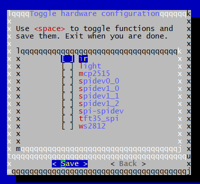
The overlay_prefix in armbianEnv.txt is not defined so I added overlay_prefix=sun50i-h616. Then I get: I was hoping that i2c3 would be there, but only the following exist. Who decides what goes into the overlays? root@orangepizero3:/boot# ls -al dtb-6.7.0-rc7-edge-sunxi64/allwinner/overlay/sun50i-h616* -rwxr-xr-x 1 root root 4203 Jan 4 13:23 dtb-6.7.0-rc7-edge-sunxi64/allwinner/overlay/sun50i-h616-fixup.scr -rwxr-xr-x 1 root root 268 Jan 4 13:23 dtb-6.7.0-rc7-edge-sunxi64/allwinner/overlay/sun50i-h616-ir.dtbo -rwxr-xr-x 1 root root 512 Jan 4 13:23 dtb-6.7.0-rc7-edge-sunxi64/allwinner/overlay/sun50i-h616-light.dtbo -rwxr-xr-x 1 root root 339 Jan 4 13:23 dtb-6.7.0-rc7-edge-sunxi64/allwinner/overlay/sun50i-h616-mcp2515.dtbo -rwxr-xr-x 1 root root 661 Jan 4 13:23 dtb-6.7.0-rc7-edge-sunxi64/allwinner/overlay/sun50i-h616-spidev0_0.dtbo -rwxr-xr-x 1 root root 661 Jan 4 13:23 dtb-6.7.0-rc7-edge-sunxi64/allwinner/overlay/sun50i-h616-spidev1_0.dtbo -rwxr-xr-x 1 root root 661 Jan 4 13:23 dtb-6.7.0-rc7-edge-sunxi64/allwinner/overlay/sun50i-h616-spidev1_1.dtbo -rwxr-xr-x 1 root root 661 Jan 4 13:23 dtb-6.7.0-rc7-edge-sunxi64/allwinner/overlay/sun50i-h616-spidev1_2.dtbo -rwxr-xr-x 1 root root 808 Jan 4 13:23 dtb-6.7.0-rc7-edge-sunxi64/allwinner/overlay/sun50i-h616-spi-spidev.dtbo -rwxr-xr-x 1 root root 616 Jan 4 13:23 dtb-6.7.0-rc7-edge-sunxi64/allwinner/overlay/sun50i-h616-tft35_spi.dtbo -rwxr-xr-x 1 root root 272 Jan 4 13:23 dtb-6.7.0-rc7-edge-sunxi64/allwinner/overlay/sun50i-h616-ws2812.dtbo
-
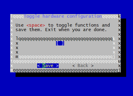
The patch for i2c3 is fine. There is no need to change anything, although the armbian developers might want to leave i2c3 disabled. The armbian-config issue is a separate item. I just want you to look at the system-hardware item in armbian-config to see it there are any items listed. My zero3 list if blank. The armbian-config is a utility for a number of things and one is to enable and disable hardware items. root@orangepizero3:~# armbian-config then System then Hardware On the Zunlong image all the devices, spi, 12c, serial etc are listed as they should be, even when they are disabled in the dtb. I suspect armbian-config does not know about H618 and is not reading the dtb. The dtb for zero3 in Zunlong is labeled with H616!?
-
@pixdrift On the i2c patch you enabled the device in the dts. Normally these devices are left disabled and I use armbian-config, system, hardware to enable the devices I require. However, this menu option is currently not working on my zero3. It just comes up with a blank list. Can you try it on a zero2?
-
I just finished testing with the build you supplied and it worked as expected. I have a temperature & pressure sensor on an 12c device that I connect to the zero3 header and then read it with rust code. There are i2c tools installed on the image that you can use to interrogate the i2c system: root@orangepizero3:~# i2cdetect -l i2c-0 i2c mv64xxx_i2c adapter I2C adapter i2c-1 i2c DesignWare HDMI I2C adapter i2c-2 i2c mv64xxx_i2c adapter I2C adapter root@orangepizero3:~# i2cdetect 2 WARNING! This program can confuse your I2C bus, cause data loss and worse! I will probe file /dev/i2c-2. I will probe address range 0x08-0x77. Continue? [Y/n] y 0 1 2 3 4 5 6 7 8 9 a b c d e f 00: -- -- -- -- -- -- -- -- 10: -- -- -- -- -- -- -- -- -- -- -- -- -- -- -- -- 20: -- -- -- -- -- -- -- -- -- -- -- -- -- -- -- -- 30: -- -- -- -- -- -- -- -- 38 -- -- -- -- -- -- -- 40: -- -- -- -- -- -- -- -- -- -- -- -- -- -- -- -- 50: -- -- -- -- -- -- -- -- -- -- -- -- -- -- -- -- 60: -- -- -- -- -- -- -- -- -- -- -- -- -- -- -- -- 70: -- -- -- -- -- -- -- -- root@orangepizero3:~# I think there are 2 i2c systems used internally by the zero3. The i2c3 that we are working on became i2c-2 as enumerated by linux. My device shows up as address 38 on the scan. Thank you for your work adding the patch.
-
@pixdrift said looking at your code block, the reference should be 'i2c3_ph_pins', not 'i2c3_pins' as 'i2c3_pins' isn't defined in the h616.dtsi, can you confirm tha makes sense and it was a typo? I notice the h6 dtsi doesn't have 'ph' in the name. Yes it was a typo. Your patch should be correct. I would expect the zero2 would benefit with the same change. I will try to build and retest.