pocosparc
-
Posts
29 -
Joined
-
Last visited
Content Type
Forums
Store
Crowdfunding
Applications
Events
Raffles
Community Map
Everything posted by pocosparc
-

Efforts to develop firmware for H96 MAX V56 RK3566 8G/64G
pocosparc replied to Hqnicolas's topic in Rockchip CPU Boxes
@Hqnicolas For the graphical libraries. Where did you copy paste this commands from? I need a bit more context than that. -
Efforts to develop firmware for H96 MAX V56 RK3566 8G/64G
pocosparc replied to Hqnicolas's topic in Rockchip CPU Boxes
Hi @Hqnicolas I am currently still doing some research as I found out that Bluetooth does not work and it has to do something with the UART1 line. I will first try to fetch the low-hanging fruits. Meanwhile, I replaced the debian with ubuntu image for now and I extracted all of the firmware drivers from my backup dump from the super.img file. I am attaching them to this post and they are coming from the vendor/firmware part. I currently do not know if they need to be statically or dynamically linked with the kernel. If they help in any way, we can include them in the armbian Linux. Link I have a few questions for you as well. Do we have some sort of PCBA schematics and the HW setup with the external hardware: direct pins connections, what goes via muxes, etc.? This would speed things up. I requested this from the buyer, but the chances are really low that he will send anything back. What is the latest dts version? Do we have it in the form of mnemonics and not as bare pointers in byte values (&gpio instead of some 0x8e value)? Now to the Bluetooth problem I found somewhere in this forum that someone fixed the Bluetooth by changing the TX and RX pins in the dts. Link to git commit Looking at what is currently in (I am using some rk3566-firefly-roc-pc.dts - there are multiple of them and changes are phandles for USB 2.0) and what is in the git and the version originally coming from this device show that there is a TX and RX swap in the file (maybe due to different PCB layouts and hoping that there is one bit that allows UART alternate function RX/TX swap - not sure as the datasheet for RK3566 is far from being useful). So the file should be at least changed to: bluetooth { compatible = "brcm,bcm43438-bt"; clocks = <0x8d 0x01>; clock-names = "lpo"; device-wake-gpios = <0x8e 0x10 0x00>; host-wake-gpios = <0x8e 0x11 0x00>; shutdown-gpios = <0x8e 0x0f 0x00>; pinctrl-names = "default"; pinctrl-0 = <0x8f 0x90 0x91>; vbat-supply = <0x24>; vddio-supply = <0x92>; status = "disabled"; }; In the original dump file there is also UART8 messing around, but I am currently not sure what her role is. @Hqnicolas If you have everything setup on you side, can you quickly check this out? Or I will try to fiddle around with armbian-config and device tree entries and let's see where it gets me. -
Efforts to develop firmware for H96 MAX V56 RK3566 8G/64G
pocosparc replied to Hqnicolas's topic in Rockchip CPU Boxes
I only use the original FTDI cables - currently C232HD which can go up to 12 Mbaud. I learned my share of these Chinese copycats - there was even a driver update, that bricked these devices as clones. On the other hand, there is also a possibility to use the ST-Link V3 JTAG expansion board as it reaches somewhere near 2.5 Mbaud (confirmed in one project of mine). Nevertheless, I installed the Armbian Bookworm v1.1 on the eMMC and I am still fiddling around it. What I can confirm that it works: 1000 MBit ethernet - speed nearly the same as on the physical PC Wifi 5 GHz Both USB ports HDMI@1440p Can`t say anything about SD-Card - still haven't received the SD card socket. I am also enclosing the whole hwinfo dump so that we will know what is on this H96 MAX v20 board. In the armbian-config I enabled the BT and IR, but still need to test them out. One thing that I saw in the dmesg is this one [ 1488.583390] of_dma_request_slave_channel: dma-names property of node '/serial@fe650000' missing or empty According to the dts file it should be the UART1 used by the Bluetooth if I am interpreting this one correctly (I need to check into the MCU datasheet but I must say that this datasheet is a disaster). Anyway, as soon as I find something new I'll keep you posted. hwinfo.txt -
Efforts to develop firmware for H96 MAX V56 RK3566 8G/64G
pocosparc replied to Hqnicolas's topic in Rockchip CPU Boxes
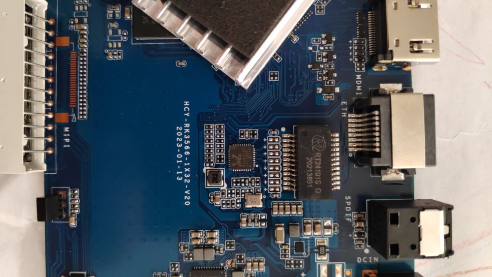
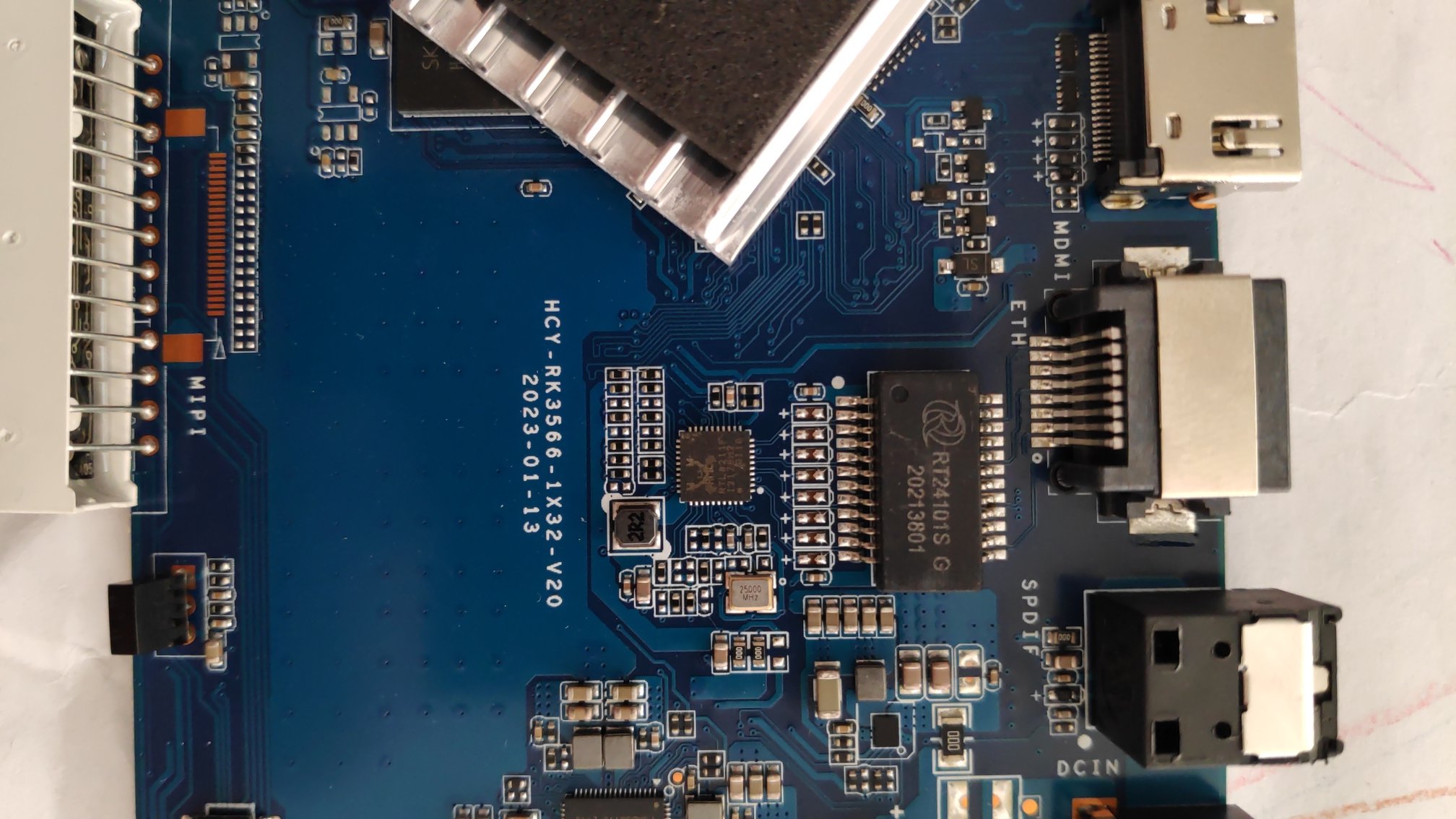
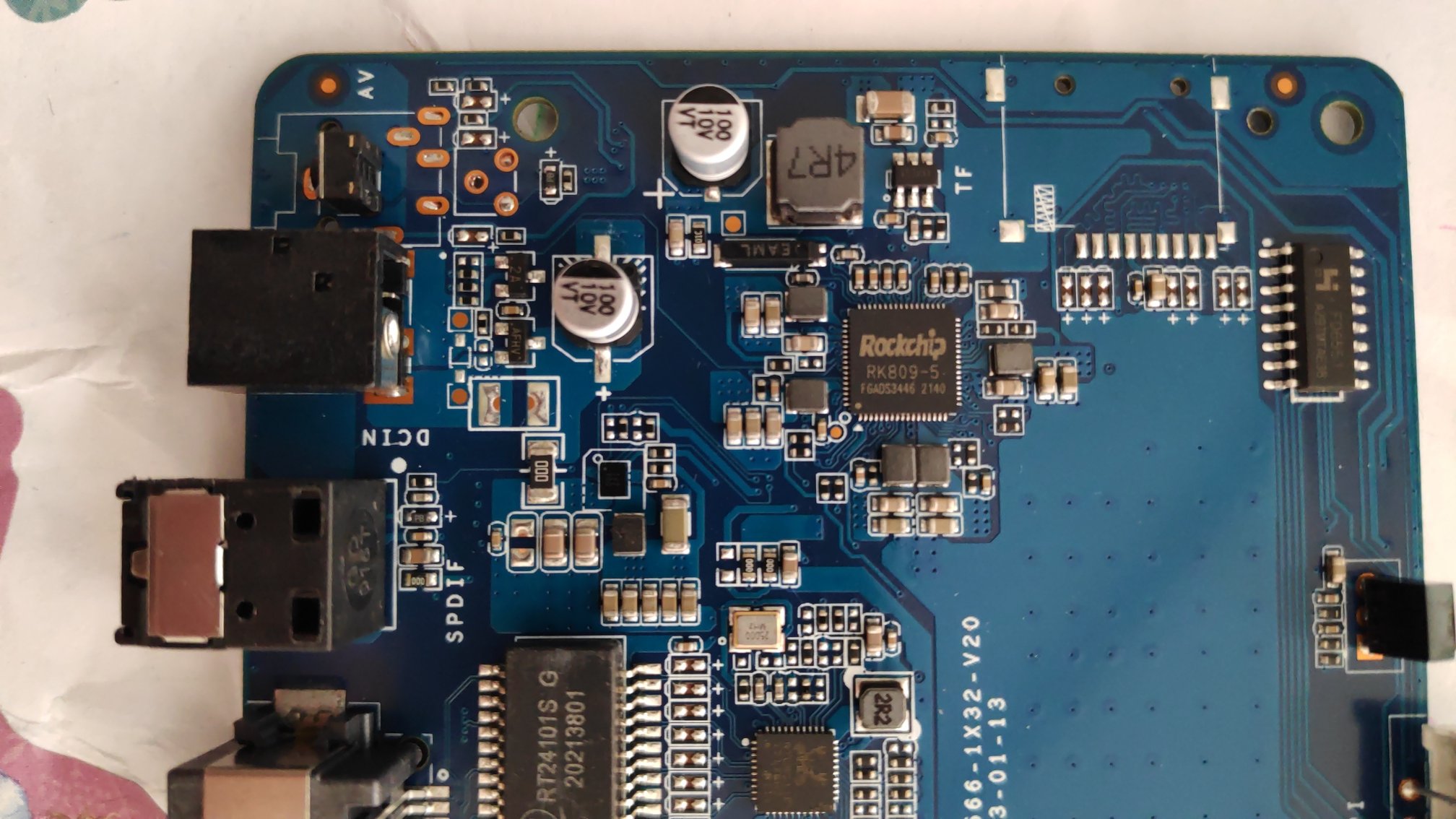
As it seems interesting, I also purchased a new device RK3566 from Aliexpress. I started at the beginning by wanting to backup what is currently on a device (just in case I fuck something up later on). After reading a few threads I embarked on a journey to dump the eMCC contents. I started with the RKDev Tool and RkDumper with various drivers in Windows 11. I did not get very far, so I gave up for now and switched to Kali. I cloned the redeveloptool git repo, tried to compile it, but it failed out of the box. There is a warning treated as an error so you need to correct the code with static pointer casting and then it compiles. Lets try to get some info from the flash: ┌──(xxx㉿yyy)-[~] └─$ sudo rkdeveloptool ld DevNo=1 Vid=0x2207,Pid=0x350a,LocationID=102 Loader ┌──(xxx㉿yyy)-[~] └─$ sudo rkdeveloptool rfi Flash Info: Manufacturer: SAMSUNG, value=00 Flash Size: 59640 MB Flash Size: 122142720 Sectors Block Size: 512 KB Page Size: 2 KB ECC Bits: 0 Access Time: 40 Flash CS: Flash<0> ┌──(xxx㉿yyy)-[~] └─$ sudo rkdeveloptool ppt **********Partition Info(GPT)********** NO LBA Name 00 00002000 security 01 00004000 uboot 02 00006000 trust 03 00008000 misc 04 0000A000 dtbo 05 0000C000 vbmeta 06 0000C800 boot 07 00020800 recovery 08 00056800 backup 09 00110800 cache 10 001D0800 metadata 11 001D8800 baseparameter 12 001D9000 logo 13 001E1000 super 14 007F5000 userdata ┌──(xxx㉿yyy)-[~] └─$ sudo rkdeveloptool rci Chip Info: 38 36 35 33 0 0 0 0 0 0 0 0 0 0 0 0 ┌──(xxx㉿yyy)-[~] └─$ sudo rkdeveloptool rcb Capability:15 07 00 00 00 00 00 00 Direct LBA: enabled First 4m Access: enabled Read Com Log: enabled Read Secure Mode: enabled New IDB: enabled So we have a nice partition info with an address table. Nice. I started to read the eMMC from the first 0 sector till the end sector 122142720. It took a while and to my surprise, the .xz file was only 12ish MB large, which was nearly impossible. So I started to analyze the hex dump and to my surprise, after a while, there were only 0xCC values read from the module. After some digging around I found out that there is a protection in uBoot (I would really like to meet this guy or some stupid project lead that has come up with this idea, which is not secure nor meaningful) that prevents reading anything larger in size than 0x10000. As luck would have it uboot was completely dumped from sector 0x4000 onwards so by extracting it from the whole dump I stored the uboot.img. I found a Python script lying around somewhere that needed to be changed to my needs (offsets and length), which dumped uboot.bin. By loading it into ghidra one could search for this function and edit the branch call. I packed everything back into uboot.img and flashed it to the sector 0x4000 and dumped again. This time the .xz was something more than 2.2 GB, which is in a range of images on China Gadgat reviews page. Just to be sure I also retried with the RkDumper as the author suggested that his tool works till driver version 4.5 (if I remember correctly) and I knew that the last time I was able to fiddle around with changing driver *.inf files was in Win7, I searched for an already available VirtualBox image and I found a torrent. With some magic, I was able to edit and add the VID and PID device IDs to the driver and install it. After some trial and error, it persuaded VB to mount the RK Loader in win7. RkDumper did its job, but way slooooower as in Linux. Anyway, I have to separate and complete dumps of the whole eMMC. In the meantime I was also curious about the serial port connector on the board so I soldered the connector. I saw an Image @Hqnicolaswhere he soldered cables for the TTL UART converted and posted UART settings. I used the same principle, but how I was wrong the ground is on this board the middle pin, which I must say that in 20 years in the embedded world have not seen. I needed to prove this with a multimeter. From the UART log I got new information U-Boot 2017.09-dirty #s02 (Jul 27 2023 - 21:33:25 +0800)<CR><LF> <CR><LF> Model: Rockchip RK3568 Evaluation Board<CR><LF> PreSerial: 2, raw, 0xfe660000<CR><LF> DRAM: 7.7 GiB<CR><LF> Sysmem: init<CR><LF> Why the use of RK3568??? I have 8 GB of DDR4 RAM running with the frequency of 1056 MHz and also that dtb files are loaded from the kernel partition. Also, the I2C frequency of the bulk converter seems to be the right one for tcs4525 (also to format is correct, but the numbers are so small that I can't read them)., what was mentioned by @Hqnicolas in the 4G thread. So the next move was to dump/extract them all. There is also one Python script somewhere in git repo that dumps them - not so perfectly though. In Linux, I converted them into dts and I am sharing them in this post. @Hqnicolas For the card reader did you only solder the socket or you also added other components (I don't have the BOM list) as it appears that a lot of condensators were not placed on the board? So the next steps are going to be analysis of the log files and probing out the armbian linux installation. androidBoot_asc.txt dts_files.7z dtb_dump.7z