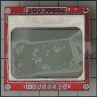
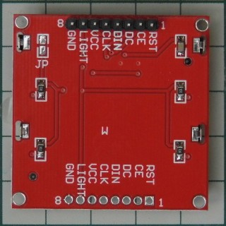
So.... This is what I've came to with Gemini:
/dts-v1/;
/plugin/;
/ {
compatible = "allwinner,sun8i-h3";
/* Target the SPI0 controller */
fragment@0 {
target = <&spi0>;
__overlay__ {
status = "okay";
#address-cells = <1>;
#size-cells = <0>;
/* Disable default spidev to free the bus for the framebuffer */
spidev@0 {
status = "disabled";
};
/* PCD8544 LCD Node */
pcd8544@0 {
compatible = "philips,pcd8544";
reg = <0>; /* Use SPI Chip Select 0 (PC3) */
spi-max-frequency = <4000000>; /* Max SPI frequency for PCD8544 */
buswidth = <8>;
/* Data/Command (DC) Pin Mapping */
/* PA6 -> Port A (0), Pin 6, Active High (0) */
dc-gpios = <&pio 0 6 0>;
/* Reset (RST) Pin Mapping */
/* PA9 -> Port A (0), Pin 9, Active High (0) */
reset-gpios = <&pio 0 9 0>;
/* Rotate display if needed (e.g., 0, 90, 180, 270) */
rotate = <0>;
};
};
};
};
I've got /dev/fb0 to show up this way. Except... It's not usable at all. Can't even print out the console. So there was no point to begin with.
What DOES work though, is a Python script using CircuitPython and Blinka:
# SPDX-FileCopyrightText: 2021 ladyada for Adafruit Industries
# SPDX-License-Identifier: MIT
"""
This demo will fill the screen with white, draw a black box on top
and then print Hello World! in the center of the display
This example is for use on (Linux) computers that are using CPython with
Adafruit Blinka to support CircuitPython libraries. CircuitPython does
not support PIL/pillow (python imaging library)!
"""
import board
import busio
import digitalio
from PIL import Image, ImageDraw, ImageFont
import adafruit_pcd8544
# Parameters to Change
BORDER = 5
FONTSIZE = 10
spi = busio.SPI(board.SCK, MOSI=board.MOSI)
dc = digitalio.DigitalInOut(board.PA6) # data/command
cs = digitalio.DigitalInOut(board.PC3) # Chip select
reset = digitalio.DigitalInOut(board.PA9) # reset
display = adafruit_pcd8544.PCD8544(spi, dc, cs, reset)
# Contrast and Brightness Settings
display.bias = 4
display.contrast = 60
# Turn on the Backlight LED
#backlight = digitalio.DigitalInOut(board.D13) # backlight
#backlight.switch_to_output()
#backlight.value = True
# Clear display.
display.fill(0)
display.show()
# Create blank image for drawing.
# Make sure to create image with mode '1' for 1-bit color.
image = Image.new("1", (display.width, display.height))
# Get drawing object to draw on image.
draw = ImageDraw.Draw(image)
# Draw a black background
draw.rectangle((0, 0, display.width, display.height), outline=255, fill=255)
# Draw a smaller inner rectangle
draw.rectangle(
(BORDER, BORDER, display.width - BORDER - 1, display.height - BORDER - 1),
outline=0,
fill=0,
)
# Load a TTF font.
font = ImageFont.truetype("/usr/share/fonts/truetype/dejavu/DejaVuSans.ttf", FONTSIZE)
# Draw Some Text
text = "It's working!"
#(font_width, font_height) = font.getsize(text)
left, top, right, bottom = font.getbbox(text)
font_width, font_height = right - left, bottom - top
draw.text(
(display.width // 2 - font_width // 2, display.height // 2 - font_height // 2),
text,
font=font,
fill=255,
)
# Display image
display.image(image)
display.show()
Using Nokia 5110 LCD library for CircuitPython
Using CircuitPython on Orange Pi PC (apparently it's the same for OPi One)
Unless /dev/fb0 on this things is even a little bit usable on the LCD, I guess I was running for circles because I was bored
I've deleted the overlay altogether since it's probably useless in this case. But I think someone else could benefit from me posting all this here, I don't know.
Either way, thank you for leading me along the way!