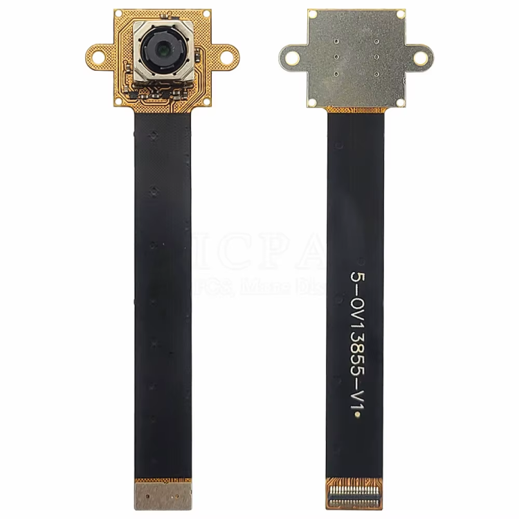
Today i decided to order two sensors with 170mm (FF, don't know if AF is working).I hope it works. Let's find out in a couple of months.
One interesting thing I've noticed :
gst-launch-1.0 v4l2src device=/dev/video11 io-mode=dmabuf ! 'video/x-raw,format=NV12,width=4224,height=3136' ! fpsdisplaysink text-overlay=1 video-sink=waylandsink text-overlay::xpos=0 text-overlay::ypos=0 -v
Setting pipeline to PAUSED ...
Pipeline is live and does not need PREROLL ...
/GstPipeline:pipeline0/GstFPSDisplaySink:fpsdisplaysink0/GstWaylandSink:waylandsink0: sync = true
Pipeline is PREROLLED ...
Setting pipeline to PLAYING ...
New clock: GstSystemClock
/GstPipeline:pipeline0/GstV4l2Src:v4l2src0.GstPad:src: caps = video/x-raw, format=(string)NV12, width=(int)4224, height=(int)3136, framerate=(fraction)120/1, interlace-mode=(string)progressive, colorimetry=(string)1:3:5:1
/GstPipeline:pipeline0/GstCapsFilter:capsfilter0.GstPad:src: caps = video/x-raw, format=(string)NV12, width=(int)4224, height=(int)3136, framerate=(fraction)120/1, interlace-mode=(string)progressive, colorimetry=(string)1:3:5:1
/GstPipeline:pipeline0/GstFPSDisplaySink:fpsdisplaysink0.GstGhostPad:sink.GstProxyPad:proxypad0: caps = video/x-raw, format=(string)NV12, width=(int)4224, height=(int)3136, framerate=(fraction)120/1, interlace-mode=(string)progressive, colorimetry=(string)1:3:5:1
/GstPipeline:pipeline0/GstFPSDisplaySink:fpsdisplaysink0/GstTextOverlay:fps-display-text-overlay.GstPad:src: caps = video/x-raw, format=(string)NV12, width=(int)4224, height=(int)3136, framerate=(fraction)120/1, interlace-mode=(string)progressive, colorimetry=(string)1:3:5:1
/GstPipeline:pipeline0/GstFPSDisplaySink:fpsdisplaysink0/GstWaylandSink:waylandsink0.GstPad:sink: caps = video/x-raw, format=(string)NV12, width=(int)4224, height=(int)3136, framerate=(fraction)120/1, interlace-mode=(string)progressive, colorimetry=(string)1:3:5:1
/GstPipeline:pipeline0/GstFPSDisplaySink:fpsdisplaysink0/GstTextOverlay:fps-display-text-overlay.GstPad:video_sink: caps = video/x-raw, format=(string)NV12, width=(int)4224, height=(int)3136, framerate=(fraction)120/1, interlace-mode=(string)progressive, colorimetry=(string)1:3:5:1
/GstPipeline:pipeline0/GstFPSDisplaySink:fpsdisplaysink0.GstGhostPad:sink: caps = video/x-raw, format=(string)NV12, width=(int)4224, height=(int)3136, framerate=(fraction)120/1, interlace-mode=(string)progressive, colorimetry=(string)1:3:5:1
/GstPipeline:pipeline0/GstCapsFilter:capsfilter0.GstPad:sink: caps = video/x-raw, format=(string)NV12, width=(int)4224, height=(int)3136, framerate=(fraction)120/1, interlace-mode=(string)progressive, colorimetry=(string)1:3:5:1
Redistribute latency...
/GstPipeline:pipeline0/GstFPSDisplaySink:fpsdisplaysink0/GstWaylandSink:waylandsink0: sync = true
/GstPipeline:pipeline0/GstFPSDisplaySink:fpsdisplaysink0/GstTextOverlay:fps-display-text-overlay: text = rendered: 12, dropped: 0, current: 23.96, average: 23.96
/GstPipeline:pipeline0/GstFPSDisplaySink:fpsdisplaysink0: last-message = rendered: 12, dropped: 0, current: 23.96, average: 23.96
/GstPipeline:pipeline0/GstFPSDisplaySink:fpsdisplaysink0/GstTextOverlay:fps-display-text-overlay: text = rendered: 13, dropped: 8, fps: 1.96, drop rate: 15.64
/GstPipeline:pipeline0/GstFPSDisplaySink:fpsdisplaysink0: last-message = rendered: 13, dropped: 8, fps: 1.96, drop rate: 15.64
/GstPipeline:pipeline0/GstFPSDisplaySink:fpsdisplaysink0/GstTextOverlay:fps-display-text-overlay: text = rendered: 13, dropped: 18, fps: 0.00, drop rate: 19.99
/GstPipeline:pipeline0/GstFPSDisplaySink:fpsdisplaysink0: last-message = rendered: 13, dropped: 18, fps: 0.00, drop rate: 19.99
WARNING: from element /GstPipeline:pipeline0/GstFPSDisplaySink:fpsdisplaysink0/GstWaylandSink:waylandsink0: A lot of buffers are being dropped.
Additional debug info:
../libs/gst/base/gstbasesink.c(3143): gst_base_sink_is_too_late (): /GstPipeline:pipeline0/GstFPSDisplaySink:fpsdisplaysink0/GstWaylandSink:waylandsink0:
There may be a timestamping problem, or this computer is too slow.
/GstPipeline:pipeline0/GstFPSDisplaySink:fpsdisplaysink0/GstTextOverlay:fps-display-text-overlay: text = rendered: 14, dropped: 27, fps: 2.00, drop rate: 17.96
/GstPipeline:pipeline0/GstFPSDisplaySink:fpsdisplaysink0: last-message = rendered: 14, dropped: 27, fps: 2.00, drop rate: 17.96
/GstPipeline:pipeline0/GstFPSDisplaySink:fpsdisplaysink0/GstTextOverlay:fps-display-text-overlay: text = rendered: 14, dropped: 37, fps: 0.00, drop rate: 19.97
/GstPipeline:pipeline0/GstFPSDisplaySink:fpsdisplaysink0: last-message = rendered: 14, dropped: 37, fps: 0.00, drop rate: 19.97
WARNING: from element /GstPipeline:pipeline0/GstFPSDisplaySink:fpsdisplaysink0/GstWaylandSink:waylandsink0: A lot of buffers are being dropped.
Additional debug info:
../libs/gst/base/gstbasesink.c(3143): gst_base_sink_is_too_late (): /GstPipeline:pipeline0/GstFPSDisplaySink:fpsdisplaysink0/GstWaylandSink:waylandsink0:
There may be a timestamping problem, or this computer is too slow.
/GstPipeline:pipeline0/GstFPSDisplaySink:fpsdisplaysink0/GstTextOverlay:fps-display-text-overlay: text = rendered: 15, dropped: 46, fps: 2.00, drop rate: 17.97
/GstPipeline:pipeline0/GstFPSDisplaySink:fpsdisplaysink0: last-message = rendered: 15, dropped: 46, fps: 2.00, drop rate: 17.97
^Chandling interrupt.
Interrupt: Stopping pipeline ...
Execution ended after 0:00:03.430005767
Setting pipeline to NULL ...
Freeing pipeline ...
but..
gst-launch-1.0 v4l2src device=/dev/video11 io-mode=dmabuf ! 'video/x-raw,framerate=30/1,format=NV12,width=4224,height=3136' ! fpsdisplaysink text-overlay=1 video-sink=waylandsink text-overlay::xpos=0 text-overlay::ypos=0 -v
Setting pipeline to PAUSED ...
Pipeline is live and does not need PREROLL ...
/GstPipeline:pipeline0/GstFPSDisplaySink:fpsdisplaysink0/GstWaylandSink:waylandsink0: sync = true
Pipeline is PREROLLED ...
Setting pipeline to PLAYING ...
New clock: GstSystemClock
/GstPipeline:pipeline0/GstV4l2Src:v4l2src0.GstPad:src: caps = video/x-raw, framerate=(fraction)30/1, format=(string)NV12, width=(int)4224, height=(int)3136, interlace-mode=(string)progressive, colorimetry=(string)1:3:5:1
/GstPipeline:pipeline0/GstCapsFilter:capsfilter0.GstPad:src: caps = video/x-raw, framerate=(fraction)30/1, format=(string)NV12, width=(int)4224, height=(int)3136, interlace-mode=(string)progressive, colorimetry=(string)1:3:5:1
/GstPipeline:pipeline0/GstFPSDisplaySink:fpsdisplaysink0.GstGhostPad:sink.GstProxyPad:proxypad0: caps = video/x-raw, framerate=(fraction)30/1, format=(string)NV12, width=(int)4224, height=(int)3136, interlace-mode=(string)progressive, colorimetry=(string)1:3:5:1
/GstPipeline:pipeline0/GstFPSDisplaySink:fpsdisplaysink0/GstTextOverlay:fps-display-text-overlay.GstPad:src: caps = video/x-raw, framerate=(fraction)30/1, format=(string)NV12, width=(int)4224, height=(int)3136, interlace-mode=(string)progressive, colorimetry=(string)1:3:5:1
/GstPipeline:pipeline0/GstFPSDisplaySink:fpsdisplaysink0/GstWaylandSink:waylandsink0.GstPad:sink: caps = video/x-raw, framerate=(fraction)30/1, format=(string)NV12, width=(int)4224, height=(int)3136, interlace-mode=(string)progressive, colorimetry=(string)1:3:5:1
/GstPipeline:pipeline0/GstFPSDisplaySink:fpsdisplaysink0/GstTextOverlay:fps-display-text-overlay.GstPad:video_sink: caps = video/x-raw, framerate=(fraction)30/1, format=(string)NV12, width=(int)4224, height=(int)3136, interlace-mode=(string)progressive, colorimetry=(string)1:3:5:1
/GstPipeline:pipeline0/GstFPSDisplaySink:fpsdisplaysink0.GstGhostPad:sink: caps = video/x-raw, framerate=(fraction)30/1, format=(string)NV12, width=(int)4224, height=(int)3136, interlace-mode=(string)progressive, colorimetry=(string)1:3:5:1
/GstPipeline:pipeline0/GstCapsFilter:capsfilter0.GstPad:sink: caps = video/x-raw, framerate=(fraction)30/1, format=(string)NV12, width=(int)4224, height=(int)3136, interlace-mode=(string)progressive, colorimetry=(string)1:3:5:1
Redistribute latency...
/GstPipeline:pipeline0/GstFPSDisplaySink:fpsdisplaysink0/GstWaylandSink:waylandsink0: sync = true
/GstPipeline:pipeline0/GstFPSDisplaySink:fpsdisplaysink0/GstTextOverlay:fps-display-text-overlay: text = rendered: 16, dropped: 0, current: 31.95, average: 31.95
/GstPipeline:pipeline0/GstFPSDisplaySink:fpsdisplaysink0: last-message = rendered: 16, dropped: 0, current: 31.95, average: 31.95
/GstPipeline:pipeline0/GstFPSDisplaySink:fpsdisplaysink0/GstTextOverlay:fps-display-text-overlay: text = rendered: 31, dropped: 0, current: 29.32, average: 30.62
/GstPipeline:pipeline0/GstFPSDisplaySink:fpsdisplaysink0: last-message = rendered: 31, dropped: 0, current: 29.32, average: 30.62
/GstPipeline:pipeline0/GstFPSDisplaySink:fpsdisplaysink0/GstTextOverlay:fps-display-text-overlay: text = rendered: 46, dropped: 0, current: 29.95, average: 30.40
/GstPipeline:pipeline0/GstFPSDisplaySink:fpsdisplaysink0: last-message = rendered: 46, dropped: 0, current: 29.95, average: 30.40
/GstPipeline:pipeline0/GstFPSDisplaySink:fpsdisplaysink0/GstTextOverlay:fps-display-text-overlay: text = rendered: 61, dropped: 0, current: 29.95, average: 30.29
/GstPipeline:pipeline0/GstFPSDisplaySink:fpsdisplaysink0: last-message = rendered: 61, dropped: 0, current: 29.95, average: 30.29
/GstPipeline:pipeline0/GstFPSDisplaySink:fpsdisplaysink0/GstTextOverlay:fps-display-text-overlay: text = rendered: 76, dropped: 0, current: 29.95, average: 30.22
/GstPipeline:pipeline0/GstFPSDisplaySink:fpsdisplaysink0: last-message = rendered: 76, dropped: 0, current: 29.95, average: 30.22
/GstPipeline:pipeline0/GstFPSDisplaySink:fpsdisplaysink0/GstTextOverlay:fps-display-text-overlay: text = rendered: 91, dropped: 0, current: 29.95, average: 30.17
/GstPipeline:pipeline0/GstFPSDisplaySink:fpsdisplaysink0: last-message = rendered: 91, dropped: 0, current: 29.95, average: 30.17
/GstPipeline:pipeline0/GstFPSDisplaySink:fpsdisplaysink0/GstTextOverlay:fps-display-text-overlay: text = rendered: 106, dropped: 0, current: 29.95, average: 30.14
/GstPipeline:pipeline0/GstFPSDisplaySink:fpsdisplaysink0: last-message = rendered: 106, dropped: 0, current: 29.95, average: 30.14
/GstPipeline:pipeline0/GstFPSDisplaySink:fpsdisplaysink0/GstTextOverlay:fps-display-text-overlay: text = rendered: 121, dropped: 0, current: 29.94, average: 30.12
/GstPipeline:pipeline0/GstFPSDisplaySink:fpsdisplaysink0: last-message = rendered: 121, dropped: 0, current: 29.94, average: 30.12
/GstPipeline:pipeline0/GstFPSDisplaySink:fpsdisplaysink0/GstTextOverlay:fps-display-text-overlay: text = rendered: 136, dropped: 0, current: 29.95, average: 30.10
/GstPipeline:pipeline0/GstFPSDisplaySink:fpsdisplaysink0: last-message = rendered: 136, dropped: 0, current: 29.95, average: 30.10
/GstPipeline:pipeline0/GstFPSDisplaySink:fpsdisplaysink0/GstTextOverlay:fps-display-text-overlay: text = rendered: 151, dropped: 0, current: 29.95, average: 30.08
/GstPipeline:pipeline0/GstFPSDisplaySink:fpsdisplaysink0: last-message = rendered: 151, dropped: 0, current: 29.95, average: 30.08
/GstPipeline:pipeline0/GstFPSDisplaySink:fpsdisplaysink0/GstTextOverlay:fps-display-text-overlay: text = rendered: 166, dropped: 0, current: 29.95, average: 30.07
/GstPipeline:pipeline0/GstFPSDisplaySink:fpsdisplaysink0: last-message = rendered: 166, dropped: 0, current: 29.95, average: 30.07
/GstPipeline:pipeline0/GstFPSDisplaySink:fpsdisplaysink0/GstTextOverlay:fps-display-text-overlay: text = rendered: 181, dropped: 0, current: 29.95, average: 30.06
/GstPipeline:pipeline0/GstFPSDisplaySink:fpsdisplaysink0: last-message = rendered: 181, dropped: 0, current: 29.95, average: 30.06
^Chandling interrupt.
Interrupt: Stopping pipeline ...
Execution ended after 0:00:06.366176166
Setting pipeline to NULL ...
Freeing pipeline ...