Search the Community
Showing results for 'waveshare'.
-

Upgrade to bookworm failed - system does not start?
bananapinas replied to bananapinas's topic in Amlogic meson
So, I got the boot log. It boots to an "emergency"? shell. Give root password for maintenance (or press Control-D to continue): after login I see: root@system:~# uname -a Linux system 5.10.60-meson64 #21.08.1 SMP PREEMPT Wed Aug 25 19:29:40 UTC 2021 aarch64 GNU/Linux I would expect 6.6.16 - no clue why it says 5.10.60, when in /boot/ anything sys 6.6.16. Full boot log follows. So what's wrong here? 😞 G12B:BL:6e7c85:2a3b91;FEAT:E0F83180:402000;POC:F;RCY:0;EMMC:0;READ:0;0. bl2_stage_init 0x01 bl2_stage_init 0x81 hw id: 0x0000 - pwm id 0x01 bl2_stage_init 0xc1 bl2_stage_init 0x02 L0:00000000 L1:00000703 L2:0000c067 L3:14000020 B2:00402000 B1:e0f83180 TE: 180255 BL2 Built : 06:17:13, Jun 28 2019. g12b gf0505d7-dirty - qi.duan@droid13 Board ID = 5 Set A53 clk to 24M Set A73 clk to 24M Set clk81 to 24M A53 clk: 1200 MHz A73 clk: 1200 MHz CLK81: 166.6M smccc: 00030852 eMMC boot @ 0 sw8 s DDR driver_vesion: LPDDR4_PHY_V_0_1_14 build time: Jun 28 2019 06:17:09 board id: 5 Load FIP HDR from eMMC, src: 0x00010200, des: 0xfffd0000, size: 0x00004000, part: 0 fw parse done Load ddrfw from eMMC, src: 0x00030200, des: 0xfffd0000, size: 0x0000c000, part: 0 Load ddrfw from eMMC, src: 0x0002c200, des: 0xfffd0000, size: 0x00004000, part: 0 PIEI prepare done fastboot data load 00000000 emmc switch 1 ok 00000000 emmc switch 2 ok fastboot data verify verify result: 255 Cfg max: 2, cur: 1. Board id: 255. Force loop cfg DDR4 probe ddr clk to 1320MHz Load ddrfw from eMMC, src: 0x00014200, des: 0xfffd0000, size: 0x0000c000, part: 0 00000000 emmc switch 0 ok Check phy result INFO : End of initialization INFO : End of read enable training INFO : End of fine write leveling INFO : End of read dq deskew training INFO : End of MPR read delay center optimization INFO : End of Write leveling coarse delay INFO : End of write delay center optimization INFO : End of read delay center optimization INFO : End of max read latency training INFO : Training has run successfully! 1D training succeed Load ddrfw from eMMC, src: 0x00020200, des: 0xfffd0000, size: 0x0000c000, part: 0 Check phy result INFO : End of initialization INFO : End of 2D read delay Voltage center optimization INFO : End of 2D write delay Voltage center optimization INFO : Training has run successfully! R0_RxClkDly_Margin==70 ps 6 R0_TxDqDly_Margi==106 ps 9 R1_RxClkDly_Margin==0 ps 0 R1_TxDqDly_Margi==0 ps 0 dwc_ddrphy_apb_wr((0<<20)|(2<<16)|(0<<12)|(0xb0):0001 2D training succeed auto size-- 65535DDR cs0 size: 2048MB DDR cs1 size: 2048MB DMC_DDR_CTRL: 00600024DDR size: 3928MB cs0 DataBus test pass cs1 DataBus test pass cs0 AddrBus test pass cs1 AddrBus test pass pre test bdlr_100_average==407 bdlr_100_min==407 bdlr_100_max==407 bdlr_100_cur==407 aft test bdlr_100_average==407 bdlr_100_min==407 bdlr_100_max==407 bdlr_100_cur==407 non-sec scramble use zero key ddr scramble enabled 100bdlr_step_size ps== 398 result report boot times 0Enable ddr reg access 00000000 emmc switch 3 ok Authentication key not yet programmed get rpmb counter error 0x00000007 00000000 emmc switch 0 ok Load FIP HDR from eMMC, src: 0x00010200, des: 0x01700000, size: 0x00004000, part: 0 Load BL3X from eMMC, src: 0x0003c200, des: 0x0172c000, size: 0x00099400, part: 0 0.0;M3 CHK:0;cm4_sp_mode 0 E30HDR MVN_1=0x00000000 MVN_2=0x00000000 [Image: g12b_v1.1.3375-8f9c8a7 2019-01-24 10:44:46 guotai.shen@droid11-sz] OPS=0x40 ring efuse init chipver efuse init 29 0c 40 00 01 11 0c 00 00 07 31 33 32 58 33 50 [0.019858 Inits done] secure task start! high task start! low task start! run into bl31 NOTICE: BL31: v1.3(release):ab8811b NOTICE: BL31: Built : 15:03:31, Feb 12 2019 NOTICE: BL31: G12A normal boot! NOTICE: BL31: BL33 decompress pass ERROR: Error initializing runtime service opteed_fast U-Boot 2015.01 (Aug 08 2021 - 16:09:39) DRAM: 3.5 GiB Relocation Offset is: d6eeb000 spi_post_bind(spifc): req_seq = 0 register usb cfg[0][1] = 00000000d7f83db0 MMC: aml_priv->desc_buf = 0x00000000d3edb7c0 aml_priv->desc_buf = 0x00000000d3eddb00 SDIO Port C: 0, SDIO Port B: 1 co-phase 0x3, tx-dly 0, clock 400000 co-phase 0x3, tx-dly 0, clock 400000 co-phase 0x3, tx-dly 0, clock 400000 emmc/sd response timeout, cmd8, status=0x1ff2800 emmc/sd response timeout, cmd55, status=0x1ff2800 co-phase 0x3, tx-dly 0, clock 400000 co-phase 0x1, tx-dly 0, clock 40000000 aml_sd_retry_refix[983]:delay = 0x0,gadjust =0x2000 [mmc_startup] mmc refix success [mmc_init] mmc init success In: serial Out: serial Err: serial vpu: error: vpu: check dts: FDT_ERR_BADMAGIC, load default parameters vpu: driver version: v20190313 vpu: detect chip type: 9 vpu: clk_level default: 7(666667000Hz), max: 7(666667000Hz) vpu: clk_level = 7 vpu: vpu_power_on vpu: set_vpu_clk vpu: set clk: 666667000Hz, readback: 666666667Hz(0x100) vpu: set_vpu_clk finish vpu: vpu_module_init_config vpp: vpp_init vpp: g12a/b osd1 matrix rgb2yuv .............. vpp: g12a/b osd2 matrix rgb2yuv.............. vpp: g12a/b osd3 matrix rgb2yuv.............. cvbs: cpuid:0x29 cvbs_config_hdmipll_g12a cvbs_set_vid2_clk ** File not found boot-logo.bmp.gz ** ** File not found boot-logo.bmp ** movi: not registered partition name, logo movi - Read/write command from/to SD/MMC for ODROID board Usage: movi <read|write> <partition|sector> <offset> <address> [<length>] - <read|write> the command to access the storage - <offset> the offset from the start of given partiton in lba - <address> the memory address to load/store from/to the storage device - [<length>] the size of the block to read/write in bytes - all parameters must be hexa-decimal only [OSD]check dts: FDT_ERR_BADMAGIC, load default fb_addr parameters [OSD]set initrd_high: 0x3d800000 [OSD]fb_addr for logo: 0x3d800000 [OSD]check dts: FDT_ERR_BADMAGIC, load default fb_addr parameters [OSD]fb_addr for logo: 0x3d800000 [OSD]VPP_OFIFO_SIZE:0xfff01fff [CANVAS]canvas init [CANVAS]addr=0x3d800000 width=5760, height=2160 cvbs: outputmode[1080p60hz] is invalid vpp: vpp_matrix_update: 2 set hdmitx VIC = 16 config HPLL = 5940000 frac_rate = 1 HPLL: 0x3b3a04f7 HPLL: 0x1b3a04f7 HPLLv1: 0xdb3a04f7 config HPLL done j = 6 vid_clk_div = 1 hdmitx phy setting done hdmitx: set enc for VIC: 16 enc_vpu_bridge_reset[1319] rx version is 1.4 or below div=10 Net: dwmac.ff3f0000 syntax error Hit Enter or space or Ctrl+C key to stop autoboot -- : 0 ## Attempting fetch boot.ini in mmc:0... ** File not found boot.ini ** ## Executing script at 04000000 Wrong image format for "source" command ## Attempting fetch boot.scr in mmc:0... ** File not found boot.scr ** ## Executing script at 04000000 Wrong image format for "source" command ## Attempting fetch /boot/boot.ini in mmc:0... 5579 bytes read in 4 ms (1.3 MiB/s) ## Executing script at 04000000 0 bytes read in 3 ms (0 Bytes/s) Found mainline kernel configuration edid extension block number : 2 Dump EDID Rawdata 000000000000000022f02033010000000a1b010380351e782ac020a656529c27 0f5054a10800d1c0b300a9c095008180810081c00101023a801871382d40582c 45000f282100001e000000fd00323c1e5011000a202020202020000000fc0048 5020323465730a2020202020000000ff0033434d37313031323246202020019f 020319b149901f0413031201021167030c0010000022e2002b023a801871382d 40582c45000f282100001e023a80d072382d40102c45800f282100001e011d00 7251d01e206e2855000f282100001e011d00bc52d01e20b82855400f28210000 1e8c0ad08a20e02d10103e96000f28210000180000000000000000000000000b No header found - count 0 hdmitx: read edid fails.. retry.. edid extension block number : 2 Dump EDID Rawdata 00ffffffffffff0022f02033010000000a1b010380351e782ac020a656529c27 0f5054a10800d1c0b300a9c095008180810081c00101023a801871382d40582c 45000f282100001e000000fd00323c1e5011000a202020202020000000fc0048 5020323465730a2020202020000000ff0033434d37313031323246202020019f 020319b149901f0413031201021167030c0010000022e2002b023a801871382d 40582c45000f282100001e023a80d072382d40102c45800f282100001e011d00 7251d01e206e2855000f282100001e011d00bc52d01e20b82855400f28210000 1e8c0ad08a20e02d10103e96000f28210000180000000000000000000000000b Manufacturer: HWP Model 3320 Serial Number 1 EDID version: 1.3 Established timings supported: 720x400@70Hz 640x480@60Hz 800x600@60Hz 1024x768@60Hz Standard timings supported: 1920x1080@60Hz 1680x1050@60Hz 1600x900@60Hz 1440x900@60Hz 1280x1024@60Hz 1280x800@60Hz 1280x720@60Hz Detailed mode (1) : Clock 148 MHz, 527 mm x 296 mm 1920 2008 2052 2200 hborder 0 1080 1084 1089 1125 vborder 0 +hsync +vsync Monitor ranges (GTF): 50-60Hz V, 30-80kHz H, max dotclock 170MHz Monitor name: HP 24es Serial number: 3CM710122F Has 1 extension blocks Checksum: 0x9f (valid) CEA extension block Extension version: 3 21 bytes of CEA data VIC 16 1920x1080@60Hz (native) VIC 31 1920x1080@50Hz VIC 4 1280x720@60Hz VIC 19 1280x720@50Hz VIC 3 720x480@60Hz VIC 18 720x576@50Hz VIC 1 640x480@60Hz VIC 2 720x480@60Hz VIC 17 720x576@50Hz Vendor-specific data block, OUI 000c03 (HDMI) Maximum TMDS clock: 170MHz YCbCr quantization: (0) RGB quantization: (0) PT scan behaviour: (2) IT scan behaviour: (2) CE scan behaviour: (3) Detailed mode (1) : Clock 148 MHz, 527 mm x 296 mm 1920 2008 2052 2200 hborder 0 1080 1084 1089 1125 vborder 0 +hsync +vsync Detailed mode (1) : Clock 148 MHz, 527 mm x 296 mm 1920 2448 2492 2640 hborder 0 1080 1084 1089 1125 vborder 0 +hsync +vsync Detailed mode (1) : Clock 74 MHz, 527 mm x 296 mm 1280 1390 1430 1650 hborder 0 720 725 730 750 vborder 0 +hsync +vsync Detailed mode (1) : Clock 74 MHz, 527 mm x 296 mm 1280 1720 1760 1980 hborder 0 720 725 730 750 vborder 0 +hsync +vsync Detailed mode (1) : Clock 27 MHz, 527 mm x 296 mm 720 736 798 858 hborder 0 480 489 495 525 vborder 0 -hsync -vsync Checksum: 0xb (valid) bestmode is custombuilt, IEEEOUI 0x000c03 HDMI Mode bestmode is custombuilt, IEEEOUI 0x000c03 HDMI Mode 161 bytes read in 3 ms (51.8 KiB/s) ** File not found uImage ** 25461312 bytes read in 713 ms (34.1 MiB/s) ** File not found dtb/amlogic/meson-g12b-odroid-n2-plus.dtb ** 80112 bytes read in 13 ms (5.9 MiB/s) ** File not found uInitrd ** 16366032 bytes read in 460 ms (33.9 MiB/s) ee_gate_off ... ## Booting kernel from Legacy Image at 01100000 ... Image Name: Linux Image Type: AArch64 Linux Kernel Image (uncompressed) Data Size: 25461248 Bytes = 24.3 MiB Load Address: 01080000 Entry Point: 01080000 Verifying Checksum ... OK ## Loading init Ramdisk from Legacy Image at 03700000 ... Image Name: uInitrd Image Type: AArch64 Linux RAMDisk Image (gzip compressed) Data Size: 16365968 Bytes = 15.6 MiB Load Address: 00000000 Entry Point: 00000000 Verifying Checksum ... OK active_slot is <NULL> Unknown command 'store' - try 'help' No dtbo patitions found load dtb from 0x1000000 ...... ## Flattened Device Tree blob at 01000000 Booting using the fdt blob at 0x1000000 No valid dtbo image found Loading Kernel Image(COMP_NONE) ... OK kernel loaded at 0x01080000, end = 0x028c8200 libfdt fdt_path_offset() returned FDT_ERR_NOTFOUND [rsvmem] fdt get prop fail. Loading Ramdisk to 3c864000, end 3d7ff990 ... OK Loading Device Tree to 000000001ffe9000, end 000000001ffff8ef ... OK Starting kernel ... uboot time: 8836498 us Give root password for maintenance (or press Control-D to continue): root@system:~# uname -a Linux system 5.10.60-meson64 #21.08.1 SMP PREEMPT Wed Aug 25 19:29:40 UTC 2021 aarch64 GNU/Linux root@system:~# cat /var/log/apt/history.log Start-Date: 2024-04-03 10:11:58 Commandline: apt upgrade --without-new-pkgs Upgrade: libnetfilter-conntrack3:arm64 (1.0.8-3, 1.0.9-3... End-Date: 2024-04-03 10:16:32 Start-Date: 2024-04-03 10:20:02 Commandline: apt full-upgrade Install: libperl5.36:arm64 (5.36.0-7+deb12u1, automatic), libnode108:arm64 (18.19.0+... End-Date: 2024-04-03 10:52:59 Start-Date: 2024-04-03 10:59:13 Commandline: apt full-upgrade Upgrade: php-redis:arm64 (6.0.2-1+0~20231128.56+debian11~1.gbp9f3071, 6.0.2-1+0~20231128.56+debian12~1.gbp9f3071), ... End-Date: 2024-04-03 11:00:44 Start-Date: 2024-04-03 11:53:03 Commandline: apt full-upgrade Install: armbian-bsp-cli-odroidn2-current:arm64 (24.2.1) Upgrade: armbian-config:arm64 (23.02.2, 24.2.1), linux-image-current-meson64:arm64 (21.08.1, 24.2.1), armbian-zsh:arm64 (23.02.2, 24.2.1), linux-u-boot-odroidn2-current:arm64 (21.08.1, 24.2.1), base-files:arm64 (12.4+deb12u5, 24.2.1-12.4+deb12u5-bookworm), linux-dtb-current-meson64:arm64 (21.08.1, 24.2.1), armbian-bsp-cli-odroidn2:arm64 (23.02.2, 24.2.1) End-Date: 2024-04-03 11:54:34 root@system:~# content of /boot drwxr-xr-x 3 root root 4096 3. Apr 11:58 . drwxrwxrwx 19 root root 4096 3. Apr 11:54 .. -rw-r--r-- 1 root root 161 3. Apr 11:58 armbianEnv.txt -rw-r--r-- 1 root root 161 2. Nov 2021 armbianEnv.txt.old -rw-r--r-- 1 root root 1531 30. Okt 2021 armbian_first_run.txt.template -rw-r--r-- 1 root root 38518 26. Aug 2021 boot.bmp -rw-r--r-- 1 root root 8075 3. Apr 11:54 boot.cmd -rw-r--r-- 1 root root 5579 16. Jun 2023 boot.ini -rw-r--r-- 1 root root 8147 3. Apr 11:54 boot.scr -rw-r--r-- 1 root root 258772 29. Feb 18:56 config-6.6.16-current-meson64 -rwxr-xr-x 1 root root 120 1. Jan 1970 display.bin lrwxrwxrwx 1 root root 26 3. Apr 11:54 dtb -> dtb-6.6.16-current-meson64 drwxr-xr-x 3 root root 4096 3. Apr 11:53 dtb-6.6.16-current-meson64 -rwxr-xr-x 1 root root 256 1. Jan 1970 edid.bin lrwxrwxrwx 1 root root 30 3. Apr 11:54 Image -> vmlinuz-6.6.16-current-meson64 -rw-r--r-- 1 root root 16365968 3. Apr 11:54 initrd.img-6.6.16-current-meson64 -rw-r--r-- 1 root root 0 3. Apr 11:54 .next -rw-r--r-- 1 root root 4424139 29. Feb 18:56 System.map-6.6.16-current-meson64 -rw-r--r-- 1 root root 25461312 9. Dez 2021 uImage lrwxrwxrwx 1 root root 30 3. Apr 11:54 uInitrd -> uInitrd-6.6.16-current-meson64 -rw-r--r-- 1 root root 16366032 3. Apr 11:54 uInitrd-6.6.16-current-meson64 -rw-r--r-- 1 root root 28346880 29. Feb 18:56 vmlinuz-6.6.16-current-meson64 content of /boot/dtb/amlogic: root@system:/boot# ls dtb/amlogic/ amlogic-c3-c302x-aw409.dtb meson-gxl-s805x-p241.dtb amlogic-t7-a311d2-an400.dtb meson-gxl-s905d-libretech-pc.dtb amlogic-t7-a311d2-khadas-vim4.dtb meson-gxl-s905d-mecool-kii-pro.dtb meson-a1-ad401.dtb meson-gxl-s905d-p230.dtb meson-axg-jethome-jethub-j100.dtb meson-gxl-s905d-p231.dtb meson-axg-jethome-jethub-j110-rev-2.dtb meson-gxl-s905d-phicomm-n1.dtb meson-axg-jethome-jethub-j110-rev-3.dtb meson-gxl-s905d-sml5442tw.dtb meson-axg-s400.dtb meson-gxl-s905d-vero4k-plus.dtb meson-g12a-radxa-zero.dtb meson-gxl-s905w-jethome-jethub-j80.dtb meson-g12a-radxa-zero-spidev.dtb meson-gxl-s905w-p281.dtb meson-g12a-sei510.dtb meson-gxl-s905w-tx3-mini.dtb meson-g12a-u200.dtb meson-gxl-s905x-hwacom-amazetv.dtb meson-g12a-x96-max.dtb meson-gxl-s905x-khadas-vim.dtb meson-g12b-a311d-bananapi-m2s.dtb meson-gxl-s905x-libretech-cc.dtb meson-g12b-a311d-khadas-vim3.dtb meson-gxl-s905x-libretech-cc-v2.dtb meson-g12b-a311d-khadas-vim3-spidev.dtb meson-gxl-s905x-nexbox-a95x.dtb meson-g12b-a311d-khadas-vim3-spinor.dtb meson-gxl-s905x-p212.dtb meson-g12b-bananapi-cm4-cm4io.dtb meson-gxm-gt1-ultimate.dtb meson-g12b-gsking-x.dtb meson-gxm-khadas-vim2.dtb meson-g12b-gtking.dtb meson-gxm-mecool-kiii-pro.dtb meson-g12b-gtking-pro.dtb meson-gxm-mini-m8s-pro.dtb meson-g12b-odroid-go-ultra.dtb meson-gxm-minix-neo-u9h.dtb meson-g12b-odroid-n2.dtb meson-gxm-nexbox-a1.dtb meson-g12b-odroid-n2l.dtb meson-gxm-q200.dtb meson-g12b-odroid-n2-plus.dtb meson-gxm-q201.dtb meson-g12b-odroid-n2-plus-spidev.dtb meson-gxm-rbox-pro.dtb meson-g12b-odroid-n2-plus-spinor.dtb meson-gxm-s912-libretech-pc.dtb meson-g12b-odroid-n2-spinor.dtb meson-gxm-t95z-plus.dtb meson-g12b-radxa-zero2.dtb meson-gxm-vega-s96.dtb meson-g12b-radxa-zero2-spidev.dtb meson-gxm-wetek-core2.dtb meson-g12b-s922x-bananapi-m2s.dtb meson-s4-s805x2-aq222.dtb meson-g12b-s922x-khadas-vim3.dtb meson-sm1-a95xf3-air.dtb meson-g12b-ugoos-am6.dtb meson-sm1-a95xf3-air-gbit.dtb meson-g12b-waveshare-cm4-io-base-b.dtb meson-sm1-bananapi-m2-pro.dtb meson-gxbb-kii-pro.dtb meson-sm1-bananapi-m5.dtb meson-gxbb-nanopi-k2.dtb meson-sm1-h96-max.dtb meson-gxbb-nexbox-a95x.dtb meson-sm1-khadas-vim3l.dtb meson-gxbb-odroidc2.dtb meson-sm1-khadas-vim3l-spidev.dtb meson-gxbb-p200.dtb meson-sm1-khadas-vim3l-spinor.dtb meson-gxbb-p201.dtb meson-sm1-odroid-c4.dtb meson-gxbb-vega-s95-meta.dtb meson-sm1-odroid-c4-spidev.dtb meson-gxbb-vega-s95-pro.dtb meson-sm1-odroid-hc4.dtb meson-gxbb-vega-s95-telos.dtb meson-sm1-sei610.dtb meson-gxbb-wetek-hub.dtb meson-sm1-x96-air.dtb meson-gxbb-wetek-play2.dtb meson-sm1-x96-air-gbit.dtb meson-gxl-s805x-libretech-ac.dtb overlay Before the last upgrade (with armbian bookworm repository), there was an directory rockchip in /boot/dtb (as link to dtb-5.10.60-meson64) root@system:/boot/dtb-5.10.60-meson64# ls -al insgesamt 16 drwxr-xr-x 4 root root 4096 9. Dez 2021 . drwxr-xr-x 3 root root 4096 3. Apr 16:48 .. drwxr-xr-x 3 root root 4096 9. Dez 2021 amlogic drwxr-xr-x 2 root root 4096 9. Dez 2021 rockchip -
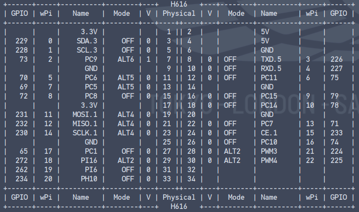
Hi all, LONG POST WARNING!!! I have been trying to get an SPI TFT screen to work with the OPI Zero 3. To that end, the first goal was to get SPI output confirmed working on physical pins 19, 21, 23 and 24. I have compiled 6.7.10-edge-sunxi64 from the build environment. The actual board is gold screen printed as a "Waveshare Spotpear 3.2" which may well be a clone, as the chipset is marked HR2046, i.e. an XPT2046 -ish which is, possibly a clone of the TI ADS7846, some or all of this sentence may be incorrect. To get the overlays to display in armbian-config it is required to name the overlays with the chipset prefix - i.e. for Opi Zero 3, this would be sun50i-h616-myoverlay.dtbo - bearing in mind the chipset for the zero 3 is actually h618, but I am aware discussions are ongoing as is the work, for which many thanks. 6.x Kernel SPI on H618: https://docs.armbian.com/Developer-Guide_Build-Preparation/ This allows compilation for the Zero 3: ./compile EXPERT=”yes” Remember to select the drivers for TFT displays in the config, I say this (not remembering exactly where they are buried) because it may be the case that they cannot be easily added after the fact - don't shoot me - I read it somewhere in my travels plus it was easier for me. Alter and compile the chosen DTS files to DTBO Set up the ENV and copy the DTBO files to the device. If activated overlays have parameters marked as “Required”, those parameters have to be set to proper values U-boot does not support overlay parameters, so changing values is implemented via executing a "fixup" script after all overlays were applied. This script uses environment variables loaded from /boot/armbianEnv.txt to change the live tree using fdt command. How to work out the numbers: // Select pins: 1st number = pos. of letter in the alphabet - 1 // 2nd number = pin number // 3rd number = DON'T CHANGE! (1 = ACTIVE_LOW, 0 = ACTIVE_HIGH) // Example: PA2 = <&pio 0 2 1> // PC7 = <&pio 2 7 0> The dtc is used to decompile/recomple the DTS to DTBO and vice versa, the exception being user created overlays, it is fully documented so not repeated here, this can be added via the "sudo armbian-add-overlay" command - which compiles and places .dts files into /boot/overlay-user/ Documentation is here: https://docs.armbian.com/User-Guide_Allwinner_overlays/ https://docs.armbian.com/Hardware_Allwinner/ https://github.com/armbian/sunxi-DT-overlays https://git.kernel.org/pub/scm/linux/kernel/git/stable/linux.git/tree/Documentation/devicetree/bindings/input/touchscreen/ads7846.txt https://github.com/rm-hull/spidev-test is invaluable for testing. The following commands have also proved useful: sudo /bin/bash -c "cat /sys/kernel/debug/pinctrl/*/pinmux-pins" sudo cat /sys/kernel/debug/gpio I also downloaded and installed the Orangepi wiringOP: Download the code of wiringOP orangepi@orangepi:~$ sudo apt update orangepi@orangepi:~$ sudo apt install -y git orangepi@orangepi:~$ git clone https://github.com/orangepi-xunlong/wiringOP.git -b next Note that the source code needs to download the code of the wiringOP next branch, please don't miss the -b next parameter. According to initial loopback testing before adding my own overlays (apply a jumper between MISO and MOSI) , via "sudo ./spidev_test -v -D /dev/spidev1.0" - this interface is functioning as expected. The Opi Zero 3 seems to have two SPI busses, and the devices on said bus need to be targeted correctly (0 or 1) hence what I think is correct, which is to add a CS (chipselect) overlay. Results of gpio readall (screenshot as copy paste mucks up the formatting): Next step was to add the dtbo files and activate via armbianEnv.txt verbosity=1 bootlogo=true console=both disp_mode=1920x1080p60 overlay_prefix=sun50i-h616 overlays=spi-ads7846 spi-double-spidev-cs spi-spidev param_spidev_spi_bus=1 param_spidev_cs=0 rootdev=UUID=22c98ce5-14a8-483f-b440-35690209c856 rootfstype=ext4 usbstoragequirks=0x2537:0x1066:u,0x2537:0x1068:u I have added my own dtbo files modified from the ones in https://github.com/armbian/sunxi-DT-overlays - which are attached. The error I am getting appears to be interrupt related, so my question is - how are the interrupts assigned, or more directly what do I put in place of PA7 which appears to be the issue the first three errors notwithstanding as I believe from reading about other OrangePi devices, the board .dtb may need looking at? dmesg | grep spi [ 1.840708] sun6i-spi 5010000.spi: Error applying setting, reverse things back [ 1.840994] sun6i-spi 5011000.spi: Error applying setting, reverse things back [ 1.849460] sun6i-spi 5010000.spi: Error applying setting, reverse things back [ 1.857263] spi-nor spi0.0: supply vdd not found, using dummy regulator [ 1.872754] spi-nor spi0.0: spi-nor-generic (16384 Kbytes) [ 7.127377] SPI driver ads7846 has no spi_device_id for ti,tsc2046 [ 7.127404] SPI driver ads7846 has no spi_device_id for ti,ads7843 [ 7.127409] SPI driver ads7846 has no spi_device_id for ti,ads7845 [ 7.127413] SPI driver ads7846 has no spi_device_id for ti,ads7873 [ 7.132367] sun50i-h616-pinctrl 300b000.pinctrl: pin PA7 already requested by spi1.0; cannot claim for 300b000.pinctrl:7 [ 7.132399] ads7846 spi1.0: failed to request pendown GPIO [ 7.132405] ads7846: probe of spi1.0 failed with error -22 There also seems to be a bit of a debate about the <compatible> tag and what should or should not be in it. I am fast approaching the end of my knowledge on this, as this is a first post, please be gentle! This is an attempt to document the fact that due diligence has been applied as much as possible, it might help others, and if nothing else, it has imbued me with admiration for those who have got this board to the state of functionality that we can enjoy today. If anything is hideously wrong, please guide (gently) as I know there are people here who have far greater detailed knowledge than I. Main takeaway - SPI works - needs tweaking, help and guidance appreciated. sun50i-h616-spi-double-spidev-cs.dts sun50i-h616-spi-ads7846.dts
-
Set fan max speed to kick in at 65C. This keeps the unit roughly at 70C or lower, when pusing all cores for an extended period of time. Checklist: [ ] My code follows the style guidelines of this project [ ] I have performed a self-review of my own code [ ] I have commented my code, particularly in hard-to-understand areas [ ] I have made corresponding changes to the documentation [X] My changes generate no new warnings [ ] Any dependent changes have been merged and published in downstream modules View the full article
-
 v2: arch: arm64: dts: amlogic: meson-g12b-waveshare-cm4-io-base-b Fan, RTC and USB support RTC requires rtc pcf85063 driver Fan requires hwmon emc2305 driver (new addition) hwmon: emc2305: fixups for driver The driver had a number of issues, checkpatch warnings/errors, and other limitations, so fix these up to make it usable. Additional: hwmon: emc2305: Change OF properties pwm-min & pwm-max to u8 hwmon: emc2305: Add calls to initialize cooling maps How was it tested? Built a new image with the following changes and booted to make sure it works as it should. Inactive: == Waveshare CM4-IO-BASE-B with BPI-CM4 Module (6.1.57-current-meson64) CPU usage: 0 Processors: Cortex-A53 @ 2016MHz 51°C, Cortex-A73 @ 2400MHz 53°C Cur freq: 1000MHz 2400MHz Fan: 0 RPM (0) <-- FAN INACTIVE Online: 0-5 Governor: ondemand Memory: 3.7G 331M Entropy: 256 Uptime: 14:12:26 up 18 min, 4 users, load average: 0.01, 0.24, 0.31 Active: == Waveshare CM4-IO-BASE-B with BPI-CM4 Module (6.1.57-current-meson64) CPU usage: 90 Processors: Cortex-A53 @ 2016MHz 82°C, Cortex-A73 @ 2400MHz 82°C Cur freq: 2016MHz 2400MHz Fan: 3368 RPM (255) <-- FAN ACTIVE Online: 0-5 Governor: ondemand Memory: 3.7G 430M Entropy: 256 Uptime: 14:19:09 up 25 min, 4 users, load average: 1.76, 1.06, 0.64 NOTE: The temps are not as they should be as they sent me a 12V instead of a 5V fan. I decided to keep the 12V to do the testing with, as I wait for the 5V to arrive. The difference between them shouldn't change the basic functionality, only the quality of the cooling. Checklist: [ ] My code follows the style guidelines of this project [ ] I have performed a self-review of my own code [ ] I have commented my code, particularly in hard-to-understand areas [ ] I have made corresponding changes to the documentation [X] My changes generate no new warnings [ ] Any dependent changes have been merged and published in downstream modules View the full article
 -
meson64/edge 6.5.y: move meson-g12b-waveshare-cm4-io-base-b.dts out of null patch, avoid patching Makefile meson64/edge 6.5.y: move meson-g12b-waveshare-cm4-io-base-b.dts out of null patch, avoid patching Makefile View the full article
-
BananaPi CM4/M2S Update to u-boot v2024.01 Fixup meson-g12b-waveshare-cm4-io-base-b.dts Removed from 'fanctrl' node: #address-cells = <1>; #size-cells = <0>; Checklist: [ ] My code follows the style guidelines of this project [ ] I have performed a self-review of my own code [ ] I have commented my code, particularly in hard-to-understand areas [ ] I have made corresponding changes to the documentation [X] My changes generate no new warnings [ ] Any dependent changes have been merged and published in downstream modules View the full article
-
https://paste.armbian.com/alinarofaf Well in the end I got reply from orange pi board maker and the display is most likely not compatible with board they only have tested the 10.1 inch display. I looked up and this display is knock off waveshare 7 inch displays for rpi wich are in dts files labeled as 35xx rpi 7 inch diplay. In the end I'm way over my head and above my skill level soo 😁 . Who would have thought displays could be soo much pain .
-
I’m trying to use a 3.5 LCD (waveshare clone) with ILI9486 + XPT2046 with my orange pi zero. My display is like this. I installed both Debian_buster_next_4.19.59 and Ubuntu_bionic_next_4.19.57 and I followed many guides in here with no success. I edited armbianEnv.txt and added these: overlays=spi-spidev spi-add-cs1 param_spidev_spi_bus=1 param_spidev_spi_cs=1 After that I ran this sudo modprobe fbtft_device custom name=fb_ili9486 gpios=dc:18,reset:2 speed=16000000 busnum=1 rotate=90 and didn’t get any error. I figured that the reset & DC pins on orange pi zero are pin22(GPIO2) and pin18(GPIO18) but I’m not 100% sure about these. With dmesg I see these: [ 179.174013] fbtft: module is from the staging directory, the quality is unknown, you have been warned. [ 179.181645] fbtft_device: module is from the staging directory, the quality is unknown, you have been warned. [ 179.183696] spidev spi1.1: spidev spi1.1 1000kHz 8 bits mode=0x00 [ 179.184295] fbtft_device: GPIOS used by 'fb_ili9486': [ 179.184307] fbtft_device: 'dc' = GPIO18 [ 179.184314] fbtft_device: 'reset' = GPIO2 [ 179.184331] spidev spi1.1: spidev spi1.1 1000kHz 8 bits mode=0x00 [ 179.184347] spi spi1.0: fb_ili9486 spi1.0 16000kHz 8 bits mode=0x00 [ 179.202576] fb_ili9486: module is from the staging directory, the quality is unknown, you have been warned. [ 179.749873] Console: switching to colour frame buffer device 60x40 [ 179.751385] graphics fb0: fb_ili9486 frame buffer, 480x320, 300 KiB video memory, 4 KiB buffer memory, fps=20, spi1.0 at 16 MHz I tried con2fbmap 1 0 but the screen remains white What else could I try? How could I debug the issue?
-
need help to drive Orangepi pc plus with waveshare 3.5inch display with xpt2046 touch driver. OS:- Armbian 22.11 Jammy XFCE Desktop version Kernal :- Kernel 5.15.y link for the os :- https://www.armbian.com/orange-pi-pc-plus/ link for display :- https://www.waveshare.com/3.5inch-hdmi-lcd.htm can any one help to drive touch screen you can message if you need more information,
-
using latest armbian server Linux bananapim2zero 5.19.15-sunxi #trunk.0071 SMP Sun Oct 16 03:56:45 UTC 2022 armv7l armv7l armv7l GNU/Linux docs from waveshare said to add "dtoverlay=sc16is752-spi1,int_pin=24" to /boot/config.txt for raspbian so i tried adding it to armbianEnv.txt and reboot but on device files or anyrthing, nothing in dmesg and /sys/bus/spi/devices/ is empty what am i doing wrong?
-
I have a Waveshare 3.5inch RPi LCD (A): https://www.waveshare.com/wiki/3.5inch_RPi_LCD_(A) Does somebody have this kind of LCD running on a Odroid C2? Is there a step by step? Because the Waveshare or Odroid Wiki is over my head 😟
-
I get a complete system hang on 'sudo ip link set can0 up type can bitrate 250000' ifconfig -a shows Can0 and no errors that i can see in dmesg I am using the Waveshare CanHat https://www.waveshare.com/rs485-can-hat.htm dtparam=spi=on dtoverlay=mcp2515-can0,oscillator=12000000,interrupt=25,spimaxfrequency=2000000 so i changed the following lines in the dts file. clock-frequency = <12000000>; spi-max-frequency = <20000000>; nothing else, I am Wired as per directions Orange Pi 3.0.6 Bullseye with Linux 5.16.17-sun50iw6 Anybody got any idea's ?? I know im close, but with a complete hang, its hard to see the error.
-
Hi guy's urgent help needed, I have banana pi m2 zero and I need the hdmi Waveshare 7inch LCD settings help. I have tried to change the config file also dts file, none of those worked. Tried to build with hdmi lcd (internet help) - none Could any one point out what is need to be done to get it work? thank you
-
After trying different distro for the BPI M2 Zero, I installed Armbian, and it works great with a standard 16:9 screen. Now I would like to use a bar LCD (Waveshare 7.9 inches); but the setup instructions are for RPI, not for Armbian, so I am not sure how you set up a screen that is not default (And I exclude that I can just plug in the screen and it will magically work. I am not using X interface since the BPI is quite slow, so I am in terminal. Thanks
-
Hi, working on Rock Pi 4B++ and trying to make our displays work. Armbian Bookworm 23.8 Raspberry Pi 7" official touchscreen Officialy supported by Radxa (https://wiki.radxa.com/Rockpi4/Raspberry_Pi_official_LCD) but it does not work on Armbian at all. Works on official Radxa Debian image. No display on Armbian. Using device tree overlay from Radxa image - does not work, of course. Waveshare 4.3" touchscreen HDMI (https://www.waveshare.com/wiki/4.3inch_HDMI_LCD_(B)) It works. Image is visible, touchscreen works but the resolution seems to be scrambled. It is 800x480 and it is correctly reported, but the image is somehow distorted. I guess the problem is the aspect ratio which is 15:9. On Raspberry Pi, it works correctly but the following settings is required: How to correct this on Armbian? Waveshare 4.3" touchscreen DSI We also have DSI version of the above display. We have not tried yet but I guess what the result will be, right? So my question is How to make these displays work correctly on Armbian? Thank you.
-
HACK: BOOT ORDER: NVMe SDCARD eMMC. NOTES: In my testing there has been no false starts or hangs up. Meaning the boot process has been stable. The downside to this in my opinion is that if there is an OS on the NVMe it will always take boot priority. The drive would need to be pulled or DD'd in order for SD eMMC boot to kick in. This has been tested by pulling the NVMe and booting from the drive and killing it; dd if=/dev/zero of=/dev/nvme0n1 bs=32768 count=32768 Tested-on: Waveshare CM4-IO-BASE-B Checklist: [ ] My code follows the style guidelines of this project [ ] I have performed a self-review of my own code [ ] I have commented my code, particularly in hard-to-understand areas [ ] I have made corresponding changes to the documentation [X] My changes generate no new warnings [ ] Any dependent changes have been merged and published in downstream modules View the full article
-
hello, My image is (Armbian BookwormXFCE desktop 20230831) and download to cm4 moudule. When I using the Bananapi CM4 base board ( https://wiki.banana-pi.org/File:BananaPi_BPI-CM4_base_board_1.jpg) the USB function is working. But I using the common RPI CM4 base board, such as waveshare's cm4 nano-b (https://www.waveshare.net/wiki/CM4-NANO-B) the USB function is not working. I compare the difference of two board's schematics. Bananapi's base board is connecting the fs1.1 usb hub ic. but waveshare's base board was connecting USB D+/D- to USB host directly . I also tried bananapi official image (both Debian and Ubuntu mate) and the wareshare's base board USB function is working.This is a bit confusing to me. Why can’t USB be found when connected USB D+ / D- directly in Armbian image? How can i solve this problem? Thanks PS. Bananpi base board SCH: https://drive.google.com/file/d/1IErCKqfWdU7gL7kUod2-wlpG7uE9EiVZ/view waveshare base board SCH: https://www.waveshare.net/w/upload/f/f5/CM4-NANO-B-SCH.pdf
-
Hi. I have an Orange PI Zero 2 It displays fine on a normal TV through HDMI but on the waveshare there is no display at all. The waveshare display works fine on the HDMI output of my Windows PC. I have chased my tail for 2 weeks looking for a solution but can't get it to work. If you can please point me in the right direction I would really appreciate it. https://www.waveshare.com/wiki/4inch_HDMI_LCD Thank You
-
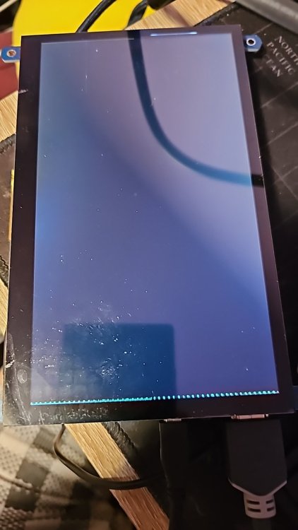
I have been trying to get a 7" waveshare touchscreen to work with the orange pi zero2. I've checked that the touchscreen isn't faulty by using with a raspberry pi. I also checked that the output from the orange pi is working by using my computer monitor. It just doesn't want to output to the touchscreen (hdmi).There seems to be some thin grey horizontal lines. I do get a flicker at startup of the orange pi, but that is about it. Any idea's? I'm new to armbian, so if you have an idea, please list me some steps or point me to some documentation to help. I appreciate the help.
-
WaveShare Touchscreen Driver Fix (Odroid) Description A number of other WaveShare screens also use ID: 0eef:0005 and therefore the patch used to enforce the VU7 driver breaks these other screens. This was the purpose of the "disable_vu7" env boot param which correctly defaults to true. However, this is ignored in boot.cmd + the patches for the kernel reverse the changes made by Hardkernel to fix this problem. I have corrected the problem by removing 0eef:0005 from the driver enforced ignore_list and changed boot.cmd to allow the "disable_vu7" to function correctly (adding usbhid quirk when set to false). How Has This Been Tested? Please describe the tests that you ran to verify your changes. Please also note any relevant details for your test configuration. Ran build of current kernel (meson 5.10) to test that changes are working as expected. They are. Touchscreen now works and is attached to the usbhid driver. Can not test functionality of VU7 (do not have VU7) however I have created this patch from the fixes applied by Hardkernel. When updating "disable_vu7"=false the screen does not function correctly (as before) and is assigned dwav_usb_mt driver implying the changes to boot.cmd work correctly. Checklist: [x] My code follows the style guidelines of this project [x] I have performed a self-review of my own code [x] I have commented my code, particularly in hard-to-understand areas [x] I have made corresponding changes to the documentation [x] My changes generate no new warnings [x] Any dependent changes have been merged and published in downstream modules View the full article
-
 @c0rnelius Apologies, my edit probably overlapped with your reply. It works fine for me with the Waveshare board. I was stupid and missed the boot switch position. Still testing with the MCUZone board, though.
 -
The BananaPi CM4 doesn't play well with a number of third party base boards in that often, USB does not work on them. Usually, that is because the third party base board designer connected the USB hub IC to an SOC OTG port without connecting a line to switch the OTG port into host mode. The problem was demonstrated at least with the Waveshare CM4 Base Board B and the MCUZone POE baseboard. In the Banana Pi forums, Sinovoip engineer "August" posted a DTBO for Ubuntu 20.04 which solves the issue by forcing host mode. Below is the DTBO decompiled to DTS. I would like to request that this overlay be updated for the Armbian kernel and included as an optional overlay into the Meson 64 / BananaPi CM4 distribution. dts-v1/; / { fragment@0 { target = <0xffffffff>; __overlay__ { controller-type = <0x01>; }; }; fragment@1 { target = <0xffffffff>; __overlay__ { otg = <0x00>; }; }; __fixups__ { dwc2_a = "/fragment@0:target:0"; usb3_phy_v2 = "/fragment@1:target:0"; }; };
-
@c0rnelius Thank you! Unfortunately, I can't get it to work on either the Waveshare or the MCUZone board. It doesn't seem to disturb the function on the bananapi base board, though. I copied the dts-file and did a sudo armbian-add-overlay meson-g12b-bananapi-cm4-waveshare-usb.dts. There is a corresponding dtbo now in /boot/overlay-user and a line "user_overlays=meson-g12b-bananapi-cm4-waveshare-usb" in /boot/armbianENV.txt I tried several flash drives and 2 different keyboards. No device shows up in dmesg or lsusb. Please let me know if I have missed anything. I'm an experienced Linux user but fairly new to armbian. EDIT: Never mind, I'm an idiot! I forgot check the boot switch on the Waveshare board. It was set to "on". Set to "off", the Waveshare board works! The MCUZone board doesn't at first glance. The boot jumper doesn't seem to do anything. I'll do some experimenting but that board is also fairly buggy- The USB hub e.g. is very temperature sensitive.
-
Hey. I have a waveshare 4.3" 480x272 screen, that I'm trying to get to work with my orange pi zero +2, or nanopi M1 plus. However, I can't get the screen to show the right resolution - that only seems possible on my raspberry pi (which I don't want to use for this project). I've been running over all the (little) info I can find, and it seems to be a general problem to get hdmi working if the screen edid is a bit flaky - is this still the case, or is it possible to get this combination of opi/nanopi to work on this display? Regards. Anders
-
BPI-CM4: Add support for the waveshare cm4-io-base-b https://www.waveshare.com/wiki/CM4-IO-BASE-B BPI-CM4: Enable usb support on waveshare baseboards via overlay BPI-SM1: Removed UART_B overlay. Short of it being an available option in the vendor kernel via overlay. I can't find any docs to support why that is. I feel it is safer that we just remove it. BPI-SM1: Add UART_A "pin-ctrl: cts rts" Checklist: [ ] My code follows the style guidelines of this project [ ] I have performed a self-review of my own code [ ] I have commented my code, particularly in hard-to-understand areas [ ] I have made corresponding changes to the documentation [X] My changes generate no new warnings [ ] Any dependent changes have been merged and published in downstream modules View the full article