

djurny
-
Posts
151 -
Joined
-
Last visited
-
Hi @ff255, There is an effort to add this calculation in the U-Boot bootscript. I'll have a look at doing this during updates to initramfs or kernel, good suggestion! Groetjes,
-
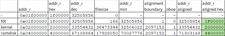
Hi @ff255, Next time, you can indeed try to calculate the load addresses using the following method: kernel_load_addr_r = (trunc( (fdt_load_addr_r + fdt_size + 1 + 64KiB) / align_to) + 1) * align_to ramdisk_load_addr_r = (trunc( (kernel_load_addr_r + kernel_size + 1) / align_to) + 1) * align_to With align_to being the alignment boundary - 2MiB for ARM64 and for other platforms it depends on their architecture, 4KiB is a safe and sane boundary to align to. edit (again): The +1 is to prevent an OBOE in U-Boot; if the next load_addr starts immediately after with no padding, the logic in U-Boot wrongly accuses the images to overlap The +64KiB is the "fdt_extrasize" which should allow for any possible addition to the DT by any of the (DT fixup) scripts. Groetjes,
-
Hi @ff255, Can you try with the following changes/additions to armbianEnv.txt: # previous load addresses # fdt_addr_r=0x01f00000 # kernel_addr_r=0x02000000 # ramdisk_addr_r=0x04000000 # new load addresses fdt_addr_r=0x01f00000 kernel_addr_r=0x02000000 ramdisk_addr_r=0x04400000 # new kernel_addr_r is aligned to 2MiB boundary # new ramdisk_addr_r is aligned to 2MiB boundary - not really neccessary afaik but "why not both?" Quick calculation below: edit: updated the sheet and put the correct numbers here Groetjes,
-
Hi @ff255, It's been a while, I'm assuming you are still getting the same error as mentioned below: Applying kernel provided DT fixup script (rockchip-fixup.scr) ## Executing script at 09000000 Wrong Ramdisk Image Format Ramdisk image is corrupt or invalid SCRIPT FAILED: continuing... The output you shared helps, but can you share a little bit more? Would need to know the following for your case: Filesize of your kernel image file Filesize of your initrd file If possible, filesize of the DT file being loaded. With those three values, we should be able to calculate the correct load addresses and try booting. (All this also presuming that your issue is that the load addresses used by U-Boot/the bootscript do not leave enough room for either a kernel or initrd file, causing one of those to overlap the start of the other.) Groetjes,
-
Hi there, I also tried to see what happens when I set the DIP to SATA0, but to my surprise, the serial console does not give any indication of a boot attempt from SATA: BootROM - 1.73 Booting from SPI flash BootROM: Bad header at offset D4000000 BootROM: Bad header at offset D4200000 BootROM: Bad header at offset D4400000 BootROM: Bad header at offset D4600000 BootROM: Bad header at offset D4800000 BootROM: Bad header at offset D4A00000 BootROM: Bad header at offset D4C00000 BootROM: Bad header at offset D4E00000 Trying Uart And yes, DIP was set to SATA0. To note: there was a blinking red LED prior to the output on the serial console. When I re-set the DIP to SPI, it boots up without issue: Booting from SPI flash U-Boot SPL 2025.10_armbian-2025.10-Se50b-Pee16-H9530-V9a59-Bbf55-R448a (Nov 23 2025 - 08:27:54 +0000) High speed PHY - Version: 2.0 Detected Device ID 6828 board SerDes lanes topology details: | Lane # | Speed | Type | -------------------------------- | 0 | 6 | SATA0 | | 1 | 5 | USB3 HOST0 | | 2 | 6 | SATA1 | | 3 | 6 | SATA3 | | 4 | 6 | SATA2 | | 5 | 5 | USB3 HOST1 | -------------------------------- High speed PHY - Ended Successfully mv_ddr: 14.0.0 DDR3 Training Sequence - Switching XBAR Window to FastPath Window DDR Training Sequence - Start scrubbing DDR3 Training Sequence - End scrubbing mv_ddr: completed successfully Trying to boot from SPI U-Boot 2025.10_armbian-2025.10-Se50b-Pee16-H9530-V9a59-Bbf55-R448a (Nov 23 2025 - 08:27:54 +0000) SoC: MV88F6828-A0 at 1600 MHz DRAM: 2 GiB (800 MHz, 32-bit, ECC enabled) Core: 32 devices, 21 uclasses, devicetree: separate MMC: mv_sdh: 0 Loading Environment from SPIFlash... SF: Detected w25q32 with page size 256 Bytes, erase size 4 KiB, total 4 MiB OK Model: Helios4 Board: Helios4 ... It almost appears that the DIP is not read out properly? What does your console say when you set the DIP to SATA0? Groetjes,
-
 Hi @wolf7250, The $PWD is an environment variable that represents the current working directory. The lone period "." also represents the current working directory. $PWD has nothing to do with your password - unless your folder names are the same as your password and/or vice versa. As to your question, yes, I would think a fresh reinstall from scratch is going to be the best way forward. But I have no idea how easy that will be with transferring OMV settings from old to new etc. OMV is unbeknownst to me. On the other hand, if the workaround with the new load addresses in `armbianEnv.txt` work (and they seem to work just fine) it's more of a matter of how "correct" you want your situation to be. Things seems to be working. Groetjes,
 -
Hi @wolf7250, You can download the package without installing as follows: cd /tmp/ mkdir fliepeltje cd /tmp/fliepeltje/ apt-get download armbian-bsp-cli-helios4-current dpkg -x armbian-bsp-cli-helios4_*.deb ${PWD:?} Then backup the current bootscript as follows: cd /boot/ sudo cp boot.cmd boot.cmd~org sudo cp boot.scr boot.scr~org Then copy the new bootscript and convert it to U-Boot script format as follows: cd /boot/ sudo cp /tmp/fliepeltje/usr/share/armbian/boot.cmd ${PWD:?} sudo mkimage -C none -A arm -T script -d boot.cmd boot.scr Then reboot to check if all went well. Gr, PS syntax is on purpose, of course you can replace ${PWD:?} with . but that might be easy to miss when reading the instruction.
-
Hi, Seems you have upgraded for several years already? Perhaps something has changed over the years, meaning that the armbian-bsp-cli package did not get installed somehow. I am not sure what will happen if you DO install that package now, so the safest best would be to just get the bootscript from the package and convert it on your machine. Gr,
-
Hi there, How about the output of dpkg --list | grep 'armbian' lsb_release -a cat /etc/armbian-release ? Just to be sure, you are using armbian right? Gr,
-
Hi, Hmm that looks like the "old" bootscript still. Odd. Can you share the output of dpkg --list | grep 'bsp-cli' ?
-
Hi there, U-Boot was updated. Can you share the contents of `/boot/boot.cmd`? Just to be sure 🙂 Groetjes,
-
Hi @wolf7250, If you have doubts or concerns, you can leave the workaround in `armbianEnv.txt` and check the serial console output to verify that U-Boot was updated and the new bootscript is doing it's job. After verfication, you can remove the workaround (fixed load addresses) from `armbianEnv.txt`. The new bootscript will try to calculate the load addresses and if it cannot do that (due to missing U-Boot command) it will default back to the fixed load addresses - which you will have overruled with the ones in `armbianEnv.txt`. Gr,
-
Hi @wolf7250, I'm not familiar with OMV, so not sure what that update/upgrade process looks like. If it will update/upgrade the armbian packages to the latest release 25.11, then the correct version of armbian-bsp-cli will be installed. The installation of that package should update /boot/boot.scr and make a new U-Boot image available that you would have to install with nand-sata-install. Gr,
-
Hi @wolf7250, The correct U-Boot and bootscript is for sure in the newest release. I built recently and all is there and working without issue on my helios4. Let's unravel what is happening for you and get that sorted out. Gr,
-
Hi @wolf7250, That does not look like the new bootscript. Did you update already? To get it working again, you can try the quick workaround as you pointed to earlier, which should allow more room for U-Boot loading kernel, initrd and the rest. Gr,