berin
-
Posts
97 -
Joined
-
Last visited
Content Type
Forums
Store
Crowdfunding
Applications
Events
Raffles
Community Map
Everything posted by berin
-
So I'm just looking for some feed back. IS there still interest out there for me to continue developing this case design for the orange pi 5? It wont be until after I move but that will be in the next few months. If there is no interest then I may or may not finish the aspects I never got to do, do to my fathers passing and all the problems it/HE created. If I don't get any feed back I may not even post that content when I do get to finishing it.
-
We will see what happens, Its been a very long time since I last posted I am sorry I am sorry. Between the stock market down turn and my fathers passing (finally 5 years stage 4 ) My father did a lot of.. .. ... stuff because he was angry about being Ill and end of life. He created a lot of problems for myself and siblings with intent! Believe me if I knew how to do and deal with go fund me like stuff I would. When all of the legal (probate) stuff is over and we "ARE" nearing the end I will be free(ed) and finish development of this project. I also have a lot of other stuff I've been working on. For example my new larger cnc machine I finished building. I can not wait to get back to being part of the community and contributing.
-
I may return to continu this project again. It has been side lined for some time dealing with a stock market problem (MMTLP) for those who dont know. MMTLP stock ticker has turned into the biggest fraud in history and the media wont touch it.
-
Desktop tools are all Im using. to do everything I have posted. ender 3 3dprinter, and a desktop cnc machine that has a working area of 7.75"x12.75". More then enough.
-
vidor You may want to look into getting a small desktop CNC machine. If you have interest in getting the tools to do everything I have done. You need a 3d printer and a small CNC machine. vidor if you know about IRC internet relay chat you can get on IRC.LIBERA.CHAT/6667 its a server. TXT based internet chat LIVE chat. You can join a room called #linuxcnc "/join #linuxcnc " would be an example of a join command. regaredless If you get into one of those rooms you can talk to people who are talking live about cnc work. There are also discord server/channels that do cnc and 3d printing. Lots of help and info out there. Once you get some basic tooling setup its amazing what you can do DIY.
-
Yes I designed and milled everything with a cnc machine and 3d printing and laser as needed. all files needed to make everything are there. The MASTER *.RSDOC files are the cad files that are "designspark" cad files. everything needed for someone to create this design on there own is posted on the github. EVERYTHING. I'm going to do some updates some time soon, dont know for sure but I have some things I'm looking to do and update. I have not done anything software wise beside setting up armbian on an SD card. I have not even gotten around to setting up the M.2 SSD card I installed. As to the LCD I have not done anything with it sadly I have just had no time between work and a stock market issue I'm dealing with. I have not updated in a while because I have just not had time. I have some projects I'm working on and I'm dealing with a massive stock market fraud lot of money lost (MMTLP) https://www.fairmarketsnow.org/ mmtlpstudios.com lots of info on twitter Its bigger then FTX its bigger then madoff. and the media wont talk about it. Lot of info out there for anyone who is just lost and wondering what is going on.
-
The OPI5 has an onboard RTC. On the back of the board near the RTC chip there are two pcb "test points". One says RTC1, the other says GRD1, I would assume a CR2032 could be connected to those points to maintain RTC function. I don't dare do anything till I get a solid answer. Can anyone give me any feedback as to options.
-
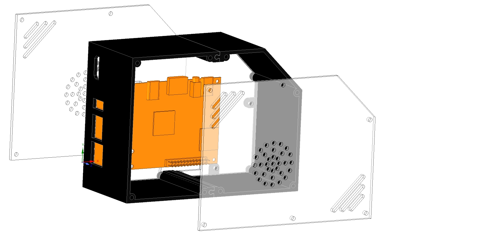
I have created a micro desktop case. It's an open design that is still in the creation phase. The shell is 3d printed, the sides are acrylic, and the opi5 mount panel can be 3d printed or made from acrylic. I'm looking for feedback with design suggestions/needs. This is the first real opi5 micro tower design currently for OPI5. My cad drawing of the OPI5 mainboard is 99.9% accurate, so if someone wants to use that as a footprint for other projects by all means. https://github.com/berin-aquaquad/orange-pi-5 I am using DesignSpark Mechanical a free cad software that is on par with Fusion360. The shell has been designed as a split body so smaller 3d printers can create it. Again, this is a work in progress, and nothing is set in stone. Planned design additions for consideration: Headphone jack front or back. USB on front. Stats LCD on front. 3D printed power button to press power button on OPI5 motherboard. GPIO header for external access, "custom design or standard web link to example, I need feedback ". RTC battery holder to make use of the onboard RTC. RGB Micro Desktop case LIGHTING options?