

berin
-
Posts
95 -
Joined
-
Last visited
Content Type
Forums
Store
Crowdfunding
Applications
Events
Raffles
Community Map
Posts posted by berin
-
-
Yes there is plenty of room. The design is not FIXED I can adjust anything design and dimension wise. That is part of why I have not built it yet I'm still working on the working design. The only dimension I have not show is the width. The case width is 62mm wide the core body. The only place the fan would not fit is the back do to the opi5 I/O and non-added i/o. Someone else asked about adding a mount for upto a 2280 SSD. This can be done as well. Just not directly mounted to the opi5, the m.2 header is in a poor location and direction on the back of the board. A remote m.2 board with a ribbon cable would work just fine. I just dont have one on hand or the need for one. If someone would like to send me an m.2 2280 ssd (any GIG size working or not) and a remote m.2 adapter as described, I'll gladly adjust the cad for an option to use it. In the next week or two I may start to build the tower. At that point I'll do a full publication of everything for spacing mount sizes, types everything. I just have a lot going on and I'm trying to finish a cad drawing for a new bar to be built in the main aft desk salan for a mega yacht (my industry/living) Sadly income/work comes first.
-
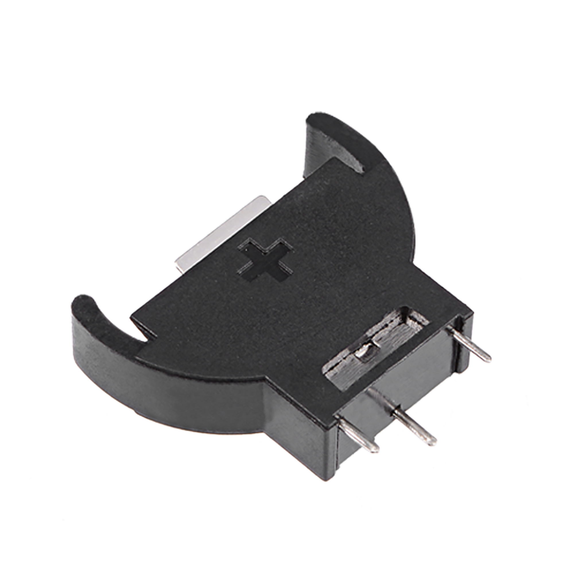
Has anyone tried a cr2032 for the RTC?
-
I've updated the git repo a lot. I'm getting closer to finished in regards to the heatsink system for the OPI5. Next project will be designing the pcb for the heatphone/mic with a cr2032 battery holder for RTC.
-
If anyone builds this I'd love to see there results or adjustments and results. I'll build it as soon as I get a few more aspects to the design finalized.
-
Does anyone have any input on this design? Suggestions likes hates? better ideas? right now I'm looking at audio jack headers PCB headers that I can make as part of a PCB to also house the RTC battery.
-
I am working on creating an RTC backup battery mount for CR2032. There are a lot of different types out there. I would like any suggestions on what kind of setup would be desired. If I do anything it will be a custom PCB that would tie into front access ports for headphone/mic. I'm looking for design suggestions if anyone has any good ideas.
-
If you guys have not seen it I am designing a micro tower for the OPI5. hence the RTC battery backup is one of the features I want to add to the CAD design. OPEN design. If you guys have not seen it I am designing a micro tower for the OPI5. hence the RTC battery backup is one of the features I want to add to the CAD design. OPEN design.
-
The OPI5 has an onboard RTC. On the back of the board near the RTC chip there are two pcb "test points". One says RTC1, the other says GRD1, I would assume a CR2032 could be connected to those points to maintain RTC function. I don't dare do anything till I get a solid answer. Can anyone give me any feedback as to options.
-
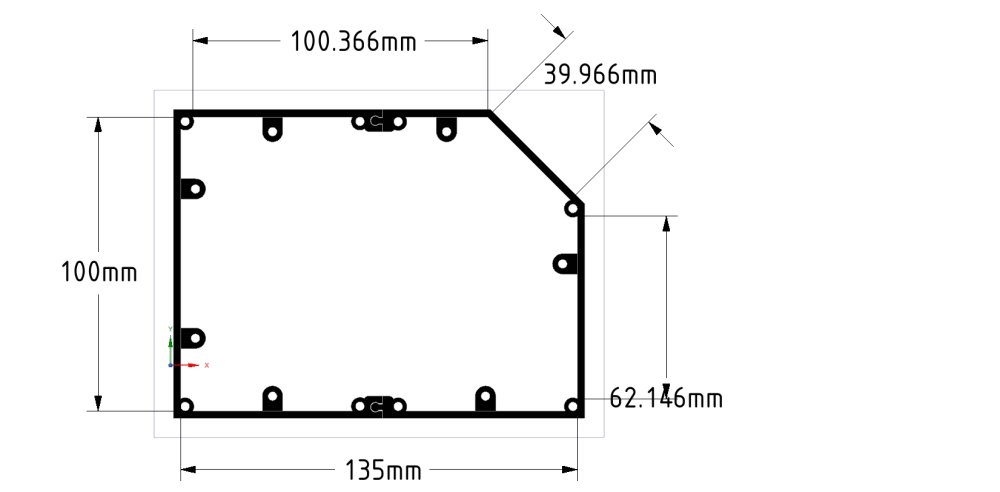
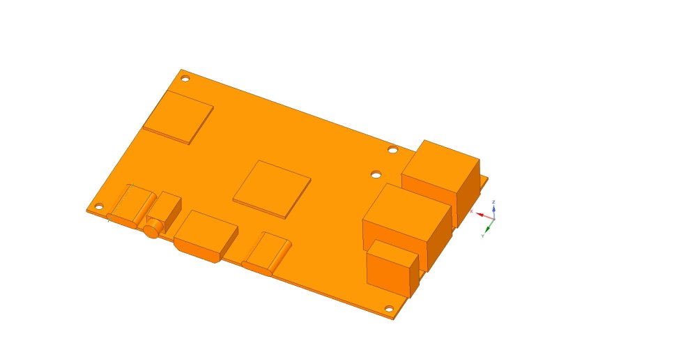
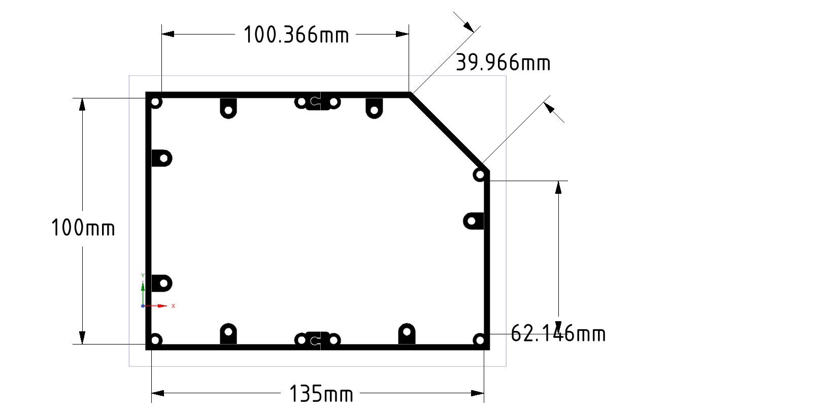
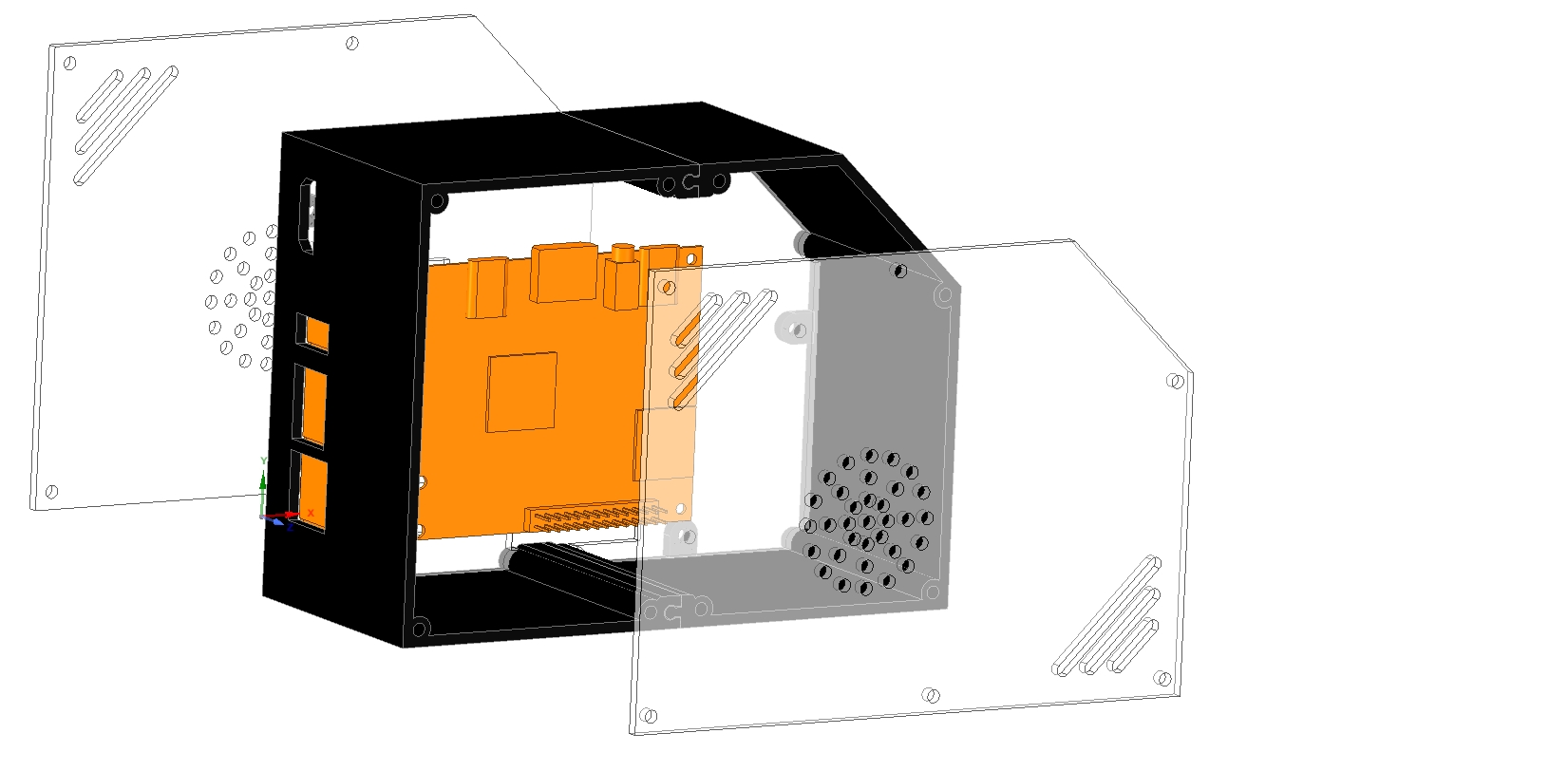
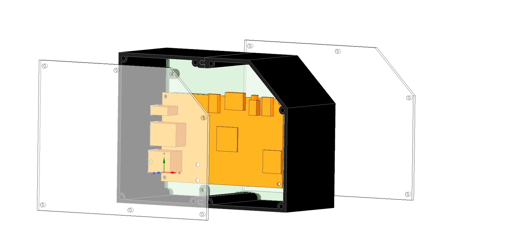
I have created a micro desktop case. It's an open design that is still in the creation phase. The shell is 3d printed, the sides are acrylic, and the opi5 mount panel can be 3d printed or made from acrylic. I'm looking for feedback with design suggestions/needs. This is the first real opi5 micro tower design currently for OPI5. My cad drawing of the OPI5 mainboard is 99.9% accurate, so if someone wants to use that as a footprint for other projects by all means.
https://github.com/berin-aquaquad/orange-pi-5
I am using DesignSpark Mechanical a free cad software that is on par with Fusion360. The shell has been designed as a split body so smaller 3d printers can create it. Again, this is a work in progress, and nothing is set in stone.

Planned design additions for consideration:
- Headphone jack front or back.
- USB on front.
- Stats LCD on front.
- 3D printed power button to press power button on OPI5 motherboard.
- GPIO header for external access, "custom design or standard web link to example, I need feedback ".
- RTC battery holder to make use of the onboard RTC.
- RGB Micro Desktop case LIGHTING options?
-
Has anyone looked at
-
-
I just got my 128gb m.2 drive. I've installed it but I have not even powered the board yet. I have no plans to power it until I get the main cpu heatsync. Yes, I know it can throttle itself. Sorry I don't like to run chips hot. @Nodonif I'm not mistaken, I believe there was a how-to on the orange pi web site. http://www.orangepi.org/html/hardWare/computerAndMicrocontrollers/details/Orange-Pi-5.html see to the orange-colored download link at the top left. it was on the web site or in the PDF files in the downloads I forget. who knows there could be something under the https://www.armbian.com/orangepi-5/ site. I will be interested to know. Currently I have downloaded the the ubuntu build from the orangepi website.
-
I have created a Cad drawing of the OPI5 motherboard and a micro desktop case design that can be 3d printed and cnc/laser milled.
https://github.com/berin-aquaquad/orange-pi-5
The Motherboard cad drawing is or should be 99% accurate. I use Designspark Cad software (free) This is a work in progress, and I have not built it yet. I'm still looking at options I want to add before I build it. As well as any last min. adjustments. The only special aspect I'll point out, is that the main body is designed as a split shell. That is to allow smaller 3d printers to be able to print the main body. I have ordered the GeeekPi Raspberry Pi 4 PWM Fan, Raspberry Pi Low-Profile CPU Cooler with RGB Cooling Fan. When I receive that in the mail, I'll ensure all measurements in my cad file are good and start building. I know there are missing vents and I/O port openings. AGAIN this is a BETA cad file post with a 99% accurate OPI5 SBC board cad file. Anyone who checks it out please give me some feedback. Though I work on luxury yachts I went to school for graphic design.

-
Thank you Thank you, I'll be here all week.
-
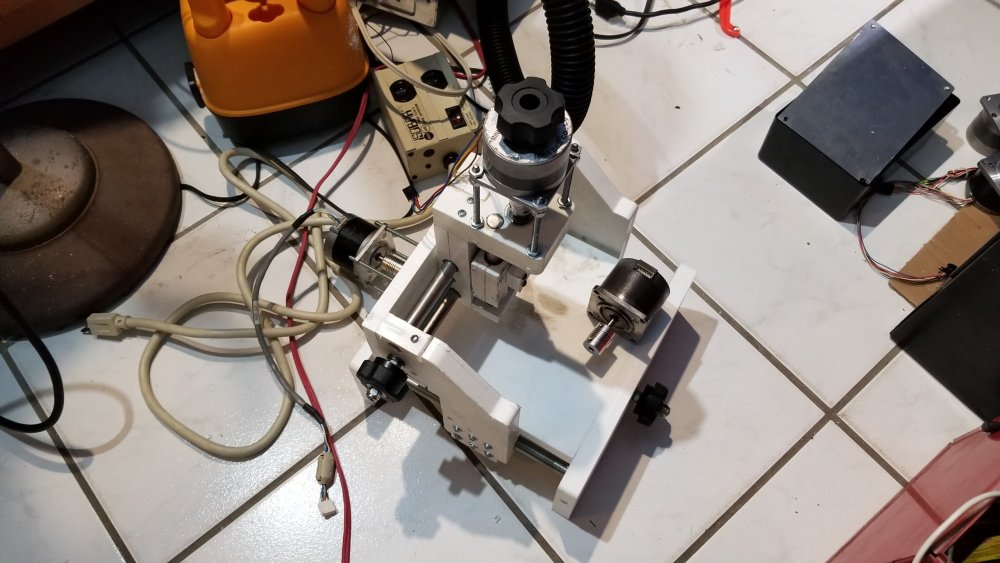
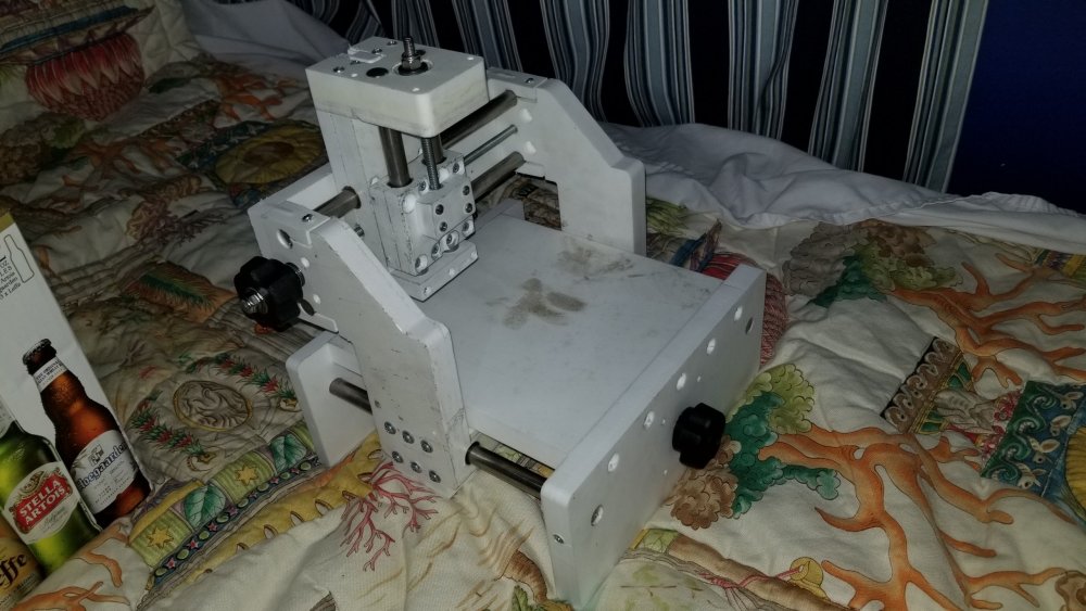
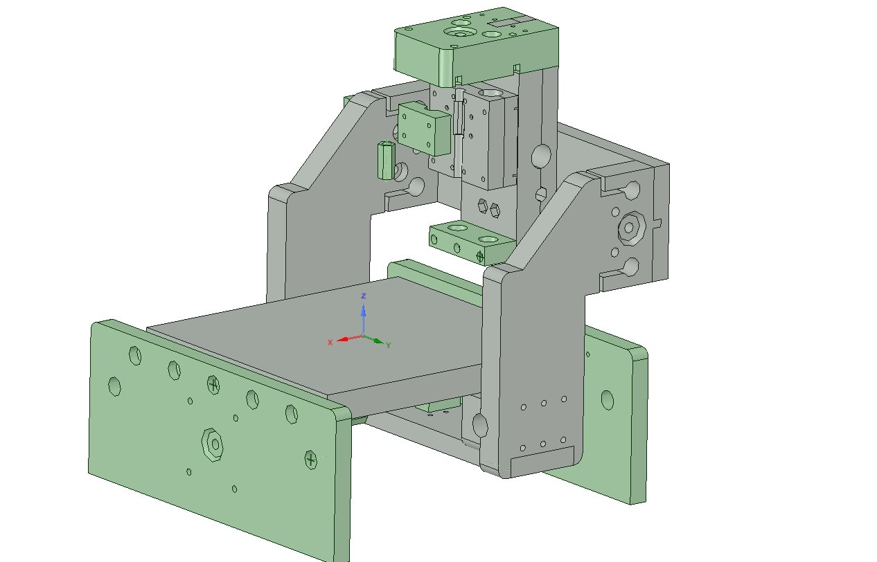
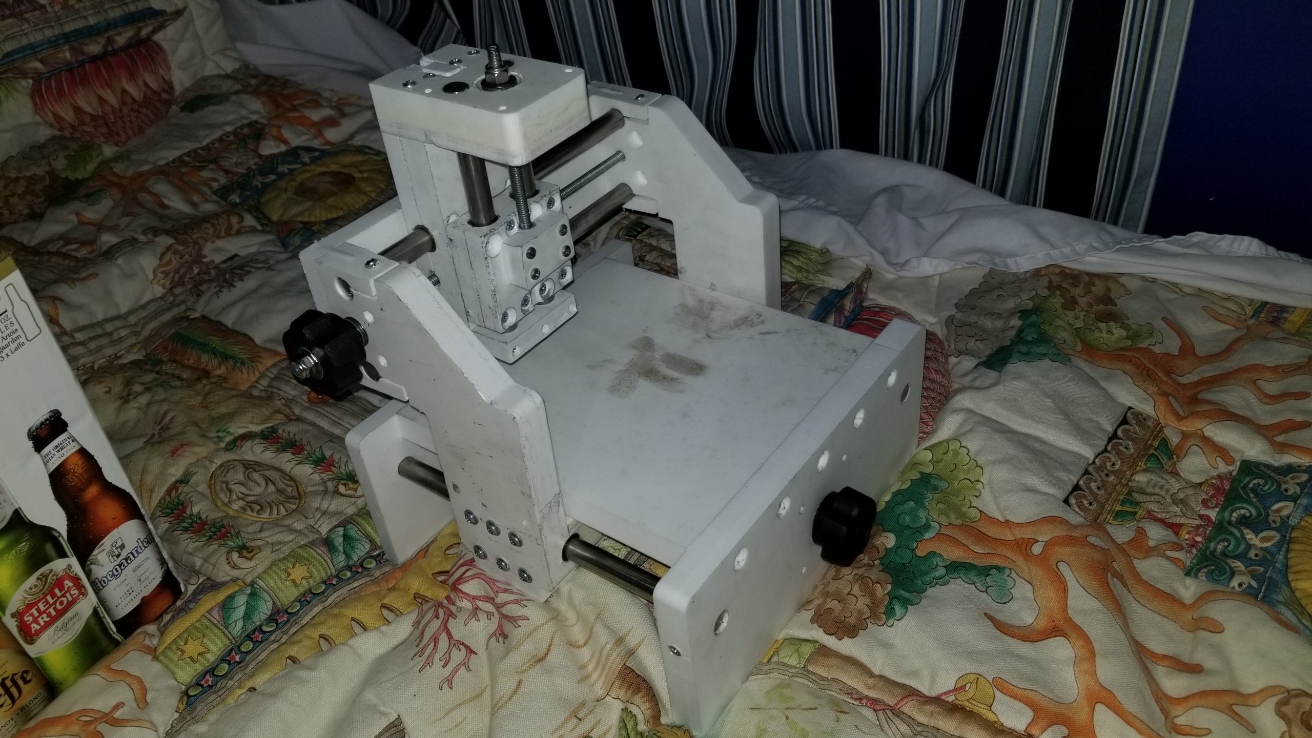
Currently I have almost finished a CNC machine I'm building for my 10yo daughter. I did all of the cad work. And milled out the parts on my cnc machine. I will be publishing my entire archive of NC files and CAD drawings etc.... to instructables or one of the other maker sites when I finish building my daughters machine. An other side/sad note. I am no longer going to use the tinkerboard for the original project I was going to use it for. So the project is kind of back burner-ed but the flame is NOT out. I just HAVE to have a working system for the cnc machine project I'm building for work and the last thing I need to get working is beyond my skill set.. If any one needs I have a collection of files given to me by other people who have setup the thinkerboard to use with MESA controllers. "cheating IMO" but it will work.
"BTW the machine in the photos I build with Starboard"

-
I have not done much with the project as of late, current status I have LCNC working on the thinkerboard but no GPIO hal driver. I have not setup a mesa controller because I dont have one and dont want to spend the money on one. I also have a ton of other stuff going on. the tinkerboard as is will work with MESA drivers using the Ethernet interface. or an SPI interface... What I'm lacking and lack the skills to do is write a lower Tear level code for a HAL driver to drive the GPIO pins directly. If anyone knows of people who may find this project interesting or be able to help PLEASE fwd them. If enough people poke ASUS they may help considering asus produced the tinkerboard.
-
Been a while. I have not touched this project but I'll be getting back into it soon. I just got my small home cnc machine up and running. Now I'll be able to start diverting time back to this project and the big cnc machine that the company that is supposed to be making the parts for for me has still been delaying me on.
-
Hi... all you have to do is install the DEB packages.. that I built if you want the RT.... they are already built. OR you can build them your self. if you want to build them your self just follow the guides and use my RT patches. unless there is a newer version out and you'll need to find newer patches. unless your going to run 4.19. unless you need something special there is not much point to compile it your self when the DEB packages are already built and posted. install. reboot. enjoy. This will give you everything you need to know for building for tinkerboard and other boards. https://docs.armbian.com/Developer-Guide_Build-Preparation/ download there image. update it update it and its hard coded to compile for armbian.
-
no no.... not easy anything but easy
") I agree it should be released with the drivers and codecs installed. no point to have to ADD it when, and I'm going to go out on a lim here MOST PEOPLE will need some if not all of those packages.
I agree it should be released with the drivers and codecs installed. no point to have to ADD it when, and I'm going to go out on a lim here MOST PEOPLE will need some if not all of those packages.
-
Is that your build? if so looks very interesting. I would suggest a dust skirt under the router motor and a vacuum. Though I do see that video is from 5 years ago. What aspect are you interested in this ongoing project? What are you looking forward to when a working release is made public? and do you have any plans?
-
Getting closer to a working linuxcnc on armbian using the tinkerboard. I'll release the alpha when the bugs are worked out. I am interested in how many people are interested in this project??
-
took a look very interesting.
-
-
So at this point its confirmed that the tinkerboard is as I expected a good candidate for running linux cnc. looking for anyone that can help get the GPIO HAL working AND the hal drivers for ethernet and spi mesa like boards for linuxcnc.


ORANGE PI 5 OPI5 micro desktop case design
in Orange Pi 5 / 5B
Posted · Edited by berin
Should I do a single combo headphone/mic jack just like what is on the OPI5? or should I break it out into a headphone jack and a mic jack on the front of the case? Also where would you guys like to see the power button? on the front vertical or the 45 degree face? I can not add an SD extension. extension adapters disable the insertion sensor in the SD socket on the board because its a physical hardware switch. So the OPI5 would never know when a card is inserted or removed because the extension adapter is always inserted into the onboard SDcard socket. The power button will be on the front vertical face no matter what. I'm not about to make some complicated lever system to push a dead straight on button (K.I.S.S.).