Ryzer
-
Posts
110 -
Joined
-
Last visited
Content Type
Forums
Store
Crowdfunding
Applications
Events
Raffles
Community Map
Everything posted by Ryzer
-
Hi WDR_s, did you manage to make any progress. if you are still getting the pinctrl errors as shown above the problems relate to PC0 (Pin 64) and PH6 (Pin 230). Are you running any addtional overlays? Can you check sudo cat /sys/kernel/debug/gpio to ensure the pins are not being used elsewhere? Best of luck Ryzer
-
Hi Wollik, I would suggest avoiding using any Port A pins as these tend to be use for the Ethernet connector hence the error message above. Please refer to the Actually schematic for the BPI MI. You can find a copy here: https://linux-sunxi.org/LeMaker_Banana_Pi. The Allwinner A20 and A10 both share the same pin controller driver, which is why it shows up the log as sun4i. Best of luck Ryzer
-
 Hi robertoj, This would most like be set somewhere within the SPI controller driver. I tried that in my other post with not much success but I will try to give it another shot. maybe you could try reversing the min and max values best of luck Ryzer
 -
Hi robertoj, There are addtional touchscreen parameters that you could try to address the cursor movement being wrong. based on what you have said I would suggest adding the line 'ti,swap-xy = <1>;' to: ads7846: ads7846@1 { reg = <1>; /* Chip Select 1 */ compatible = "ti,ads7846"; spi-max-frequency = <1000000>; status = "okay"; pinctrl-names ="default"; pinctrl-0 = <&ads7846_pins>; interrupt-parent = <&pio>; interrupts = <0 7 2>; /* PA7 IRQ_TYPE_EDGE_FALLING */ pendown-gpio = <&pio 0 7 1>; /* PA7 */ /* driver defaults, optional*/ ti,x-min = /bits/ 16 <0>; ti,y-min = /bits/ 16 <0>; ti,x-max = /bits/ 16 <0xFFF>; ti,y-max = /bits/ 16 <0xFFF>; ti,pressure-min = /bits/ 16 <0>; ti,pressure-max = /bits/ 16 <0xFFFF>; ti,x-plate-ohms = /bits/ 16 <400>; }; In regards to the crashing that, will be a bit harder to pin down. Thinking about I would suggest double checking 'interrupts = <0 7 2>;' as I would have expected it to be something like 'interrupts = <0 7 IRQ_TYPE_EDGE_FALLING>. That said, it does appear to be registering correctly when looking here: Does /proc/interrupts list the gpio as being set to trigger on falling edge as expected? 24MHz is the maximum speed that the ili9341 will work at in spi mode. It may be possible that there indeed problems with the driver but without investigating deeper its hard to say. Raspberry Pi have there own distinct linux kernel fork so the problems mentioned may not be common to the mainline kernel used by Armbian. I wonder if the crashes are possibly caused by the cs lines of both devices being pulled low at the same time under certain conditions. best of luck Ryzer
-
Hi robertoj, I can see some lines that look problematic. Firstly you are defining cs-gpio twice. Once here: Note - Remember that 0 refers to the native cs line (PC3) Here the pinctrl references are wrong. I am not sure how strictly the ordering matters but for clarity 'pinctrl-names' should be before the actual pin control nodes. Adding spi-add-cs1.dtbo is not needed as all it does it defined the pins to use as cs lines which you have already done above anyway. My other suggestion would be to look into what the latest bindings should for the ads7846 touch controller. Let me know how you get on with following overlay: best of luck Ryzer
-
Hi Usual user, Please find attached the dts sources copied from cache/sources/linux-kernel-worktree/6.6__sunxi_armhf/arch/arm/boot/dts/allwinner sun4i-a10.dtsi sun4i-a10-pcduino.dts sun4i-a10-pcduino2.dts The most recent version of the spi-ili9341-tft.dts overlay can be found here: https://github.com/Ryzer58/sunxi-DT-overlays/blob/master/examples/spi-ili9341-tft.dts cheers Ryzer
-
Hi Robertoj, That was due to a little mixup in the overlays used with similiar names of spi-ili9341-tft and spi-tft-ili9341.dts. When working with spi-ili9341-tft.dts I assumed it was correct and working but I when I double checked the environment file on the 5.15.88 kernel the working overlay I was using was spi-tft-ili9341.dts. I cant remember what exactly the issue was as intially spi-ili9341-tft.dts did not work when compiled under 5.15.88. I have since recompiled it and it now does indeed work mostly, the only bit I need to address is getting the backlight to come on automatically which it does on spi-tft-ili9341.dts but not on spi-ili9341-tft.dts. I should have remember from before that the reset pin is not strictly necessary and in my case the reset pin aligns with the board reset pin. One other thing I have to be careful of is the connections do not appear to be great so if I accidently knock the screen it goes white then I have to reboot to get the display back.
-
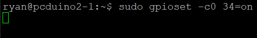
Hi usual user, Ok I have updated to the latest version of libgpiod so now I can run gpioset -c0 34=on. This is the result:
-
Hi robertoj Glad you found a solution that works. Just be mindful that the fb tft based drivers such as fb_ili9341 are no longer actively maintained and likely to be removed in future. I dont know the full details but just a brief overview of things are supposed to work. The underlying spi hardware will always be controlled by the spi controller driver as defined in the main SOC dtsi file which then exchanges information with the display driver at the other end which in our case is the ili9341. drm_mipi_dbi is a dependance of the ili9341. Again I dont know its exact function but I imagine its something to do with configure the resoution of the display as it can also be used to define a custom display as well. Looking at spi-max-frequency this appears to be set to high, it should be no greater than 24MHz. Getting h264 may be possible but it depends on the display data from the display engine being able to be sent spi controller. It should be but you will need to check in and figure out which input device relates to the ADS7846 touch controller. All the best Ryzer
-
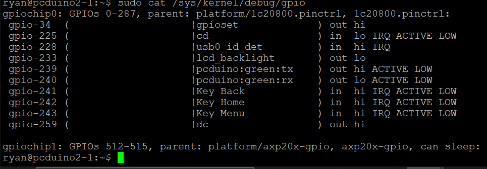
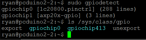
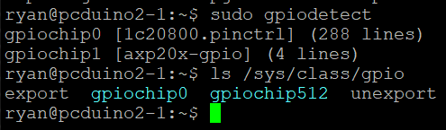
Hi usual user, I will admit that is a bit strange. gpiochip1 is the mapping for the IO on axp209 pmic. For some reason it is assigned a different base under kernel 6.6. if we look at gpio via the sysfs approuch this is more clearer to see. Another issue is that neither is 100% accurate as some listed gpio lines do not actually exist as there is not a single port that is associated with 32 pins. https://linux-sunxi.org/A20/PIO That said if the mapping was incorrect then surely the dc pin and backlight pins woud not be correct either. Kernel 5.15.88 Kernel 6.6: Are you sure this is right as it returns an error and gpioset -h does not list a -c option
-
Hi usual user, I have attempted your suggestion but to no avail unfortunately. I did a bit of digging into previous commits to armbian build and found an interesting patch for the 5.15 kernel series:drv-spi-spi.c-fix-cs_gpio-spi-support.patch This like a promising place to start from. Unfortunately I no longer have a copy of the kernel source code specificly for 5.15.88. and only managed to find 5.15.165 listed on kernel.org. I guess I’ll need to closely examine spi.c under kernel 6.6 to figure out how it now handles GPIO-based chip selects. Just to confirm all the builds where current when they where created. The only additional alterations that I had to do was a patch to enable hdmi support and adjust the perf unit IRQ number so that it does not conflict with a serial port.
-
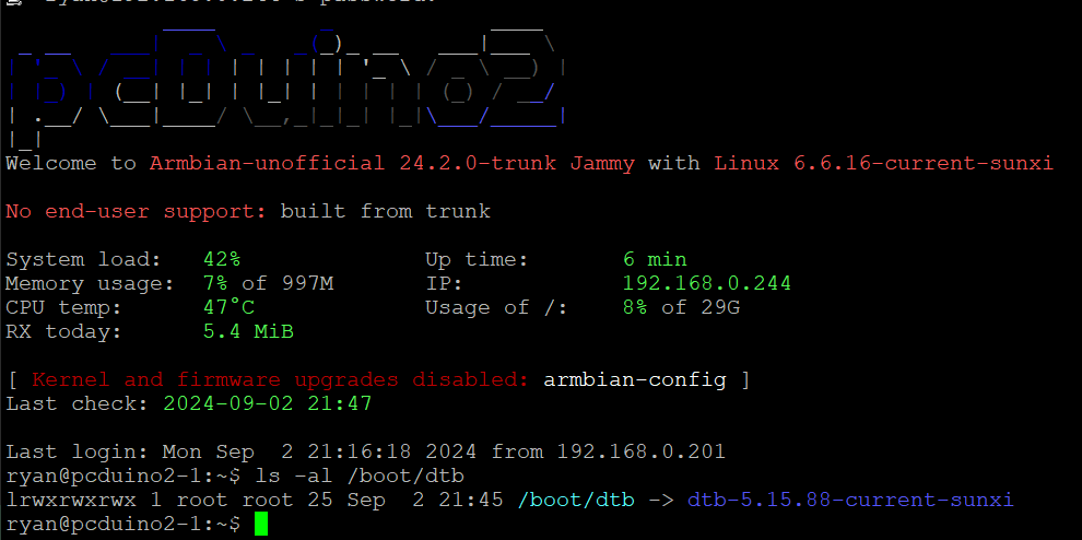
Hi usual user, which location do I source the old dtb from as there is a pcduino2.dtb at /boot/dtb/ as well as /boot/dtb-5.15.88. So far I have tried with fetching the spi-ili9341-tft.dtbo from the prevous build to no avail. As another test I have tried using the spi-gpio module in place of spi-sun4i but have been unable to get that to work at all. Do you have an A20 based board that you are able to test with the current kernel? If anyone else is experiencing the same issue it would be good to know.
-
Hi robertoj, Before you revert to an old image I would suggest one last thing. If the screen is grey then that is progress, xserver just has to be configured to use it. I encountered the exact same problem when trying to the display module working with the Raspberry PI as alternative option. Then I remembered that we need to create a configuration file. It needs to be saved to "/etc/X11/xorg.conf.d/". Call it something like 99-fbdev.conf and write the following: Section "Device" Identifier "myfb" Driver "fbdev" Option "fbdev" "/dev/fb1" EndSection if you do 'sudo dmesg | grep drm' it will list all the display devices although we can also see the devices list in the xorg.log. [ 93.742] (II) Platform probe for /sys/devices/platform/display-engine/drm/card0 [ 93.743] (II) xfree86: Adding drm device (/dev/dri/card2) [ 93.743] (II) Platform probe for /sys/devices/platform/soc/1c40000.gpu/drm/card2 [ 93.745] (II) xfree86: Adding drm device (/dev/dri/card1) [ 93.745] (II) Platform probe for /sys/devices/platform/soc/1c69000.spi/spi_master/spi0/spi0.0/drm/card1 Even though it is not erroring, it is not finding a valid configuration so it switches back to the default display device which is normally the display engine. [ 93.745] (II) no primary bus or device found [ 93.745] falling back to /sys/devices/platform/display-engine/drm/card0 All the best Ryzer
-
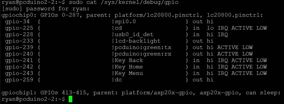
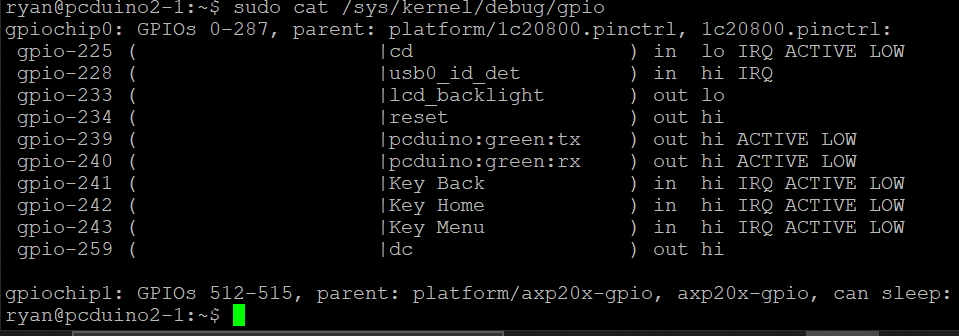
Hi Usual user, Thanks for your suggestion but looking under "/sys/kernel/debug/gpio" provides similiar output. kernel 5.15.88: Kernel 6.6.16:
-
Hi robertoj, Glad you are making some progress. I know it says spi0.0 in the log but really it is still pointing to spi1. To get the id in software to match the physical id we have to explicity assign. This is not critical and does not impact on actual function but if you want to set it to match to avoid confusion, this can be done by adding the following fragment to the overlay: fragment@0 { target-path = "/aliases"; __overlay__ { spi1 = "/soc/spi@01c69000"; }; }; I see that the display is being mapped to /dev/fb1, from my experience it tends not to work unless mapped to /dev/fb0. You could try FRAMEBUFFER=/dev/fb1 and see if that triggers any sort of output. From what I tell can from the Sunxi wiki the Orange Pi Zero can provide composite ouput that appears to be enabled by default which would likely be mapped to /dev/fb0. Best of luck Ryzer
-
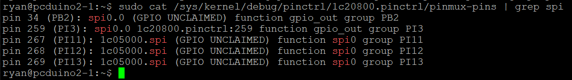
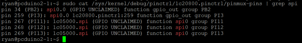
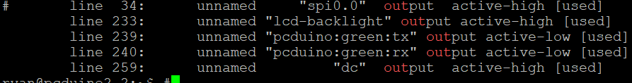
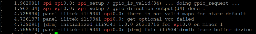
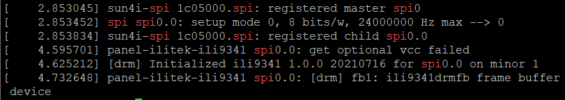
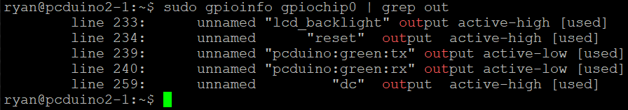
I have recently been trying to get my spi ili9341 working under kernel 6.6, having gotten it working previously. I checked to ensure there were no changes in the overlay required by the newer kernel. I confirmed that the pins were configured correctly and that the ILI9341 DRM module had loaded.. Despite this I was met with a white screen. Think I must have missed something I swapped out my SD card for another using an image based on kernel 5.15.88, where I was able to recieve a display. Looking back over the dmesg log, I noticed a slight difference in behaviour with the older kernel. firstly we can clearly see that the SPI driver is requesting to use gpio 34 as a chip select line compared to kernel 6.6. Secondly using gpioinfo to see which pins are currently set as output, to observe if gpio 34 has been set. A slight draw back with this approach is that it does not currently acknowledge when gpio are configured for spi. Kernel 5.15.88: Kernel 6.6.16: I later tried again but with my Pcduino3 using a more recent build based on kernel of 6.6.44 but achieved the same result. To confirm my theory that the problem lies somewhere within the chip select intialisation, I temporarily rerouted the pin used for the display to the Pcduino's native chip select pin (PI10) and recompiled the overlay to match. Now when I booted the pcduino I was met with a terminal window.
-
Hi robertoj, Looking at your overlay it looks almost there. The &spi0_pi_pins that I used will not work for the H3 as it has no port I exposed. Looking at pin controller section of the sunxi-h3-h5.dtsi spi0 only seems routed to one place so in this case you only need spi1_pins. please see here: https://git.kernel.org/pub/scm/linux/kernel/git/stable/linux.git/tree/arch/arm/boot/dts/allwinner/sunxi-h3-h5.dtsi?h=v6.6.47 If using the native chip select cs-gpios is not necessary unless you have a second chip select line that is normal gpio. Unfortunately it wont show under /dev/ however you can check if an spi bus is enabled by looking at /proc/device-tree/soc/spi@1c69000/status. Its odd that you dont have it by default, I thought both are still included at least in the current kernels. Best of luck Ryzer
-
Hi robertoj, Do not activate spidev as I have mention above, doing so will cause a conflict. The Spidev driver and the ili9341 cannot access the spi bus at the same time. Without seeing your currently overlay its difficult to provide further assistance. Best of luck Ryzer
-
Hi robertoj, I have had some partial success with kernel 6.6 with my pcduino however I am not sure if the chip select issue I am currently facing would be relevant to you given its A10 which use a different SPI driver to the H3. What I would Intially suggest is making sure the pins that you are using are configure in the pin controller. You can check this by looking /sys/kernel/debug/pinctrl/1c20800.pinctrl/pinmux-pins and then using grep spi1 to filter out pins other than those used by spi1. Secondly check that the drm based ili9341 driver is present on your system and that you are not using the older fb_ili9341 which has been deprecated and has no garentee of working in newer kernels. Best of luck Ryzer
-
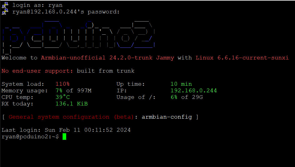
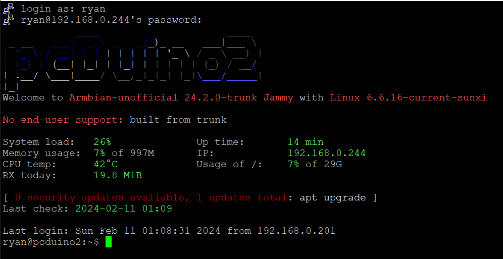
When testing my most recent builds using the Armbian build framework I found that I was experiencing a constant load greater than 1.00. At first, I thought this is probably normal to have a load during the system boot but after waiting over 10 minutes I found that the load did not decrease. Firstly, I used HTOP but could not find a process that was heavy utilising the CPU with the relative CPU usage show as low. Next I tried using TOP which revealed a process called kworker: freezeable_power. Trying to search for the issue I did not find much until I came across this old forum post that described the same issues I was having: https://forum.armbian.com/topic/7575-k-worker-problem-on-a20-based-boards/page/2/ Sure enough, removing the sun4i-gpadc caused the average system load to drop and even relative CPU usage dropped to around 1% utilisation rather than the usual idling around 20 – 25%. The risk is losing the CPU temperature. Following the advice from the latest post I found that setting mode to disabled seemed to do the trick of bringing down the system load while retaining CPU temperature reading. I achieved this by modifying rc.local with the line: Echo disabled > /sys/devices/virtual/thermal/thermal_zone1/mode Admittedly this works reasonably well however it take around approximately 5 minutes for system load to drop down to a more expected 15% - 20% on idle. I am hoping that someone with an understanding of the touchscreen control on the A10/A20 may be able to provide a fix as this out of my depth with my current knowledge. Without rc.local edit: with rc.local edit:
-
Hi Roland, Ok it looks like I2C is being set up correctly but I would advise against activating all I2C interfaces at once, in case it leads to problems. As you identified earlier you only need to have I2C2 enabled. Could you please provide the code that you are trying to run to communicate with the BME280 or show what kind of error message you are getting. Unfortunately I don't have that sensor myself to test, I only have a BNO055 9 dof. So far I have had no major issues with I2C unless it has been broken by a recent kernel update. Pin 53 is the physical number on the SOC, not the board pin number on the board. for a more detailed description of the pin mapping see: https://linux-sunxi.org/GPIO as well as checking the schematic of the Banana Pi to see what pins are brought out. Best of luck Ryzer
-
Hi Roland, What is the name of the sensor that you using and how exactly are you trying to communicate with it via i2c? The Banana Pi M1 is based around the Allwinner A20 which is a completely different SOC to the Raspberry Pi so the i2c-bcm2708 driver will not be compatible. Seeming as i2cdetect works, this suggest that i2c-dev is indeed loaded, as far as I aware it simple under /dev for i2c devices such as /dev/i2c2 which would not exist if i2c-dev has not been loaded. you can double check this by running sudo dmesg | grep i2c. from my experience you should not need define the pins as this should already be declared in the i2c overlay. if you check the pin control configuration it should show that PB20 and PB21 that they are setup for i2c2. You find this by typing sudo cat /sys/kernel/debug/pinctrl/1c20800.pinctrl/pinmux-pins | grep i2c. the output should look like this: pin 32 (PB0): 1c2ac00.i2c (GPIO UNCLAIMED) function i2c0 group PB0 pin 33 (PB1): 1c2ac00.i2c (GPIO UNCLAIMED) function i2c0 group PB1 pin 52 (PB20): 1c2b400.i2c (GPIO UNCLAIMED) function i2c2 group PB20 pin 53 (PB21): 1c2b400.i2c (GPIO UNCLAIMED) function i2c2 group PB21 Best of luck Ryzer
-
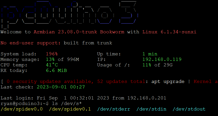
Hi there, I have been testing this on my Pcduino3 (Same A20 Soc) and was able to generate spidev0.0 and spidev0.1 using the old examples overlays. All initially did was change the compatibility field to use "armbian,spi-dev". The original example overlays can be found here: https://github.com/armbian/sunxi-DT-overlays/tree/master/examples. I then found that I need to add the pinctrl nodes as demonstrated above to actually configure the pins correctly. You can check the pins are set correctly by using sudo cat /sys/kernel/debug/pinctrl/1c20800.pinctrl/pinmux-pins | grep PI1. Please see the resulting overlay below: /dts-v1/; /plugin/; / { compatible = "allwinner,sun4i-a10", "allwinner,sun7i-a20", "allwinner,sun8i-h3", "allwinner,sun50i-a64", "allwinner,sun50i-h5"; fragment@2 { target = <&pio>; __overlay__ { spi0_pi_pins: spi0-pi-pins { pins = "PI11", "PI12", "PI13"; function = "spi0"; }; spi0_cs0_pi_pin: spi0-cs0-pi-pin { pins = "PI10"; function = "spi0"; }; spi0_cs1_pi_pin: spi0-cs1-pi-pin { pins = "PI14"; function = "spi0"; }; }; }; fragment@1 { target = <&spi0>; __overlay__ { #address-cells = <1>; #size-cells = <0>; status = "okay"; pinctrl-names = "default"; pinctrl-0 = <&spi0_pi_pins>; spi-max-frequency = <1000000>; num-chipselects = <2>; spidev@0 { reg = <0>; /* Chip Select 0 */ compatible = "armbian,spi-dev"; pinctrl-names = "default"; pinctrl-0 = <&spi0_cs0_pi_pin>; status = "okay"; }; spidev@1 { reg = <1>; /* Chip Select 1 */ compatible = "armbian,spi-dev"; pinctrl-names = "default"; pinctrl-0 = <&spi0_cs1_pi_pin>; status = "okay"; }; }; }; }; btw you can use the "armbian-add-overlay" command to automatically compile and move into the overlay fold best of luck Ryzer
-
Initially I attempted upgrading the kernel from 6.1.26 to 6.1.33 using the build scripts to generate the newer kernel and headers. After rebooting I found that the system just appeared to hang around starting kernel. I did wait 10 minutes at first, thinking that perhaps their maybe some stuff going on in the background but after that conclude that it had most certainly crashed. The frustrating thing being that I did not appear to get any errors come through the debug port. At this point I assumed that perhaps something may have broke during the upgrade. My second attempt was using a completely fresh compiled image but unfortunately the result was still the same. U-Boot SPL 2022.10-armbian (Jun 15 2023 - 13:35:35 +0000) DRAM: 1024 MiB CPU: 912000000Hz, AXI/AHB/APB: 3/2/2 Trying to boot from MMC1 ns16550_serial serial@1c28000: pinctrl_select_state_full: uclass_get_device_by_phandle_id: err=-19 U-Boot 2022.10-armbian (Jun 15 2023 - 13:35:35 +0000) Allwinner Technology CPU: Allwinner A20 (SUN7I) Model: LinkSprite pcDuino3 DRAM: 1 GiB Core: 52 devices, 23 uclasses, devicetree: separate WDT: Not starting watchdog@1c20c90 MMC: mmc@1c0f000: 0 Loading Environment from FAT... Unable to use mmc 0:1... Unknown monitor Unknown monitor In: serial Out: serial Err: serial Net: eth_designware ethernet@1c50000: Can't get reset: -2 eth0: ethernet@1c50000 230454 bytes read in 12 ms (18.3 MiB/s) Unknown monitor starting USB... Bus usb@1c14000: USB EHCI 1.00 Bus usb@1c14400: USB OHCI 1.0 Bus usb@1c1c000: USB EHCI 1.00 Bus usb@1c1c400: USB OHCI 1.0 scanning bus usb@1c14000 for devices... 2 USB Device(s) found scanning bus usb@1c14400 for devices... 1 USB Device(s) found scanning bus usb@1c1c000 for devices... 1 USB Device(s) found scanning bus usb@1c1c400 for devices... 1 USB Device(s) found scanning usb for storage devices... 0 Storage Device(s) found Autoboot in 1 seconds, press <Space> to stop switch to partitions #0, OK mmc0 is current device Scanning mmc 0:1... Found U-Boot script /boot/boot.scr 4121 bytes read in 2 ms (2 MiB/s) ## Executing script at 43100000 U-boot loaded from SD Boot script loaded from mmc 154 bytes read in 2 ms (75.2 KiB/s) 16660327 bytes read in 690 ms (23 MiB/s) 8480576 bytes read in 355 ms (22.8 MiB/s) Found mainline kernel configuration 42775 bytes read in 9 ms (4.5 MiB/s) 5532 bytes read in 5 ms (1.1 MiB/s) Applying kernel provided DT fixup script (sun7i-a20-fixup.scr) ## Executing script at 45000000 Kernel image @ 0x42000000 [ 0x000000 - 0x816740 ] ## Loading init Ramdisk from Legacy Image at 43400000 ... Image Name: uInitrd Image Type: ARM Linux RAMDisk Image (gzip compressed) Data Size: 16660263 Bytes = 15.9 MiB Load Address: 00000000 Entry Point: 00000000 Verifying Checksum ... OK ## Flattened Device Tree blob at 43000000 Booting using the fdt blob at 0x43000000 EHCI failed to shut down host controller. Loading Ramdisk to 4901c000, end 49fff727 ... OK Loading Device Tree to 48fa9000, end 4901bfff ... OK DE is present but not probed Starting kernel ... I will gratefully for any possible insight Cheers Ryzer
-
After watching a video tutorial on youtube I have attempted to use the build scripts to create a newer image for my Pcduino V2. I had been initially using an image that I found on the archives which uses kernel 4.14, this worked fine for the most part apart from shutting down which would fail 9/10 to shutdown normally. the only way I could ensure that it would shutdown was to do poweroff -f otherwise it just went into a state where most things such as the wifi and usbs would no longer be detected and i was greeted with the message failed to reach target.poweroff. from what I could find out about the issue suggested that it was some kind of issue with systemd, but I could not find an actual solution. Anyway I thought I would have ago at creating an image, I suppose given the age of the board issues are to be expected. I have had some success in fixes some of the issues encountered despite being relatively new to Armbian and Linux in general. After learning how to create patches, firstly I managed to get UART2 which was originally conflicting with the PMU as they shared the same assigned interrupt number of 3. From what I can tell this different to the normal PMU which I find that the power chip is normally referred to as there also appears to be some internal component within the A10 also called the 'PMU' . This seems to be something to do with core monitor as the A20 chip features 2 of these 'PMU's, one for each core. Looking at the user manual suggest that this should be 49. Now this has been patched I can use UART2 without getting an error although it is exposed as ttyS1 for some reason that I have yet to figure out. The second patch I made was to get HDMI output working which I was able to do by using the Cubieboard as a point of reference as they share similar hardware. I found this out by initially using images targeted at the Cubieboard as they appear to be a lot more recent and provide HDMI out so I knew that copying the sections other would. Additionally I found a way to get it working on my main 4K monitor after coming across a post which suggested lowering the size of the CMA buffer from the default size of 128mb to 64mb. Now again the main problem I face is when I try to shutdown, this time it relates to a kernel panic: [ 2508.547646] WARNING: CPU: 0 PID: 1 at drivers/i2c/i2c-core.h:41 i2c_transfer+ 0x93/0xbc [ 2508.561239] No atomic I2C transfer handler for 'i2c-1' [ 2508.571971] Modules linked in: cfg80211 btusb btintel btrtl btbcm bluetooth a xp20x_adc sun4i_gpadc_iio industrialio lima gpu_sched r8188eu(C) sun4i_ts ecdh_g eneric rfkill ecc joydev input_leds sunxi_cedrus(C) v4l2_mem2mem videobuf2_dma_c ontig videobuf2_memops videobuf2_v4l2 videobuf2_common zram evdev uio_pdrv_genir q display_connector uio cpufreq_dt nfsd auth_rpcgss sch_fq_codel nfs_acl lockd g race sunrpc ip_tables x_tables autofs4 pinctrl_axp209 sun4i_gpadc sunxi phy_gene ric gpio_keys icplus(E) [ 2508.635429] CPU: 0 PID: 1 Comm: systemd-shutdow Tainted: G C E 5 .15.32-sunxi #trunk [ 2508.651044] Hardware name: Allwinner sun4i/sun5i Families [ 2508.663328] [<c010cea9>] (unwind_backtrace) from [<c01095b9>] (show_stack+0x1 1/0x14) [ 2508.678114] [<c01095b9>] (show_stack) from [<c09cc035>] (dump_stack_lvl+0x2b/ 0x34) [ 2508.692774] [<c09cc035>] (dump_stack_lvl) from [<c011b5a9>] (__warn+0xad/0xc0 ) [ 2508.707135] [<c011b5a9>] (__warn) from [<c09c5c23>] (warn_slowpath_fmt+0x5f/0 x7c) [ 2508.721785] [<c09c5c23>] (warn_slowpath_fmt) from [<c0795a5f>] (i2c_transfer+ 0x93/0xbc) [ 2508.736949] [<c0795a5f>] (i2c_transfer) from [<c0795ac3>] (i2c_transfer_buffe r_flags+0x3b/0x50) [ 2508.752981] [<c0795ac3>] (i2c_transfer_buffer_flags) from [<c0697577>] (regma p_i2c_write+0x13/0x24) [ 2508.769489] [<c0697577>] (regmap_i2c_write) from [<c0694023>] (_regmap_raw_wr ite_impl+0x48b/0x560) [ 2508.786008] [<c0694023>] (_regmap_raw_write_impl) from [<c0694139>] (_regmap_ bus_raw_write+0x41/0x5c) [ 2508.802806] [<c0694139>] (_regmap_bus_raw_write) from [<c06939b1>] (_regmap_w rite+0x35/0xc8) [ 2508.818874] [<c06939b1>] (_regmap_write) from [<c06948b5>] (regmap_write+0x29 /0x3c) [ 2508.834263] [<c06948b5>] (regmap_write) from [<c069e723>] (axp20x_power_off+0 x23/0x30) [ 2508.850053] [<c069e723>] (axp20x_power_off) from [<c0137ded>] (__do_sys_reboo t+0xf5/0x16c) [ 2508.866244] [<c0137ded>] (__do_sys_reboot) from [<c0100061>] (ret_fast_syscal l+0x1/0x52) [ 2508.882357] Exception stack(0xc154dfa8 to 0xc154dff0) [ 2508.895490] dfa0: 4321fedc bef4aaa8 fee1dead 28121969 4321f edc 00000000 [ 2508.911883] dfc0: 4321fedc bef4aaa8 bef4aaa4 00000058 bef4aaa8 bef4aaa4 fffff 000 bef4aaac [ 2508.928357] dfe0: 00000058 bef4aa1c b6eb81b5 b6e367e6 [ 2508.941715] ---[ end trace 8381275b8efb7dea ]--- [ 2510.584023] i2c i2c-1: mv64xxx: I2C bus locked, block: 1, time_left: 0 [ 2511.128016] Kernel panic - not syncing: Attempted to kill init! exitcode=0x00 000000 [ 2511.175494] CPU: 0 PID: 1 Comm: systemd-shutdow Tainted: G WC E 5 .15.32-sunxi #trunk [ 2511.192848] Hardware name: Allwinner sun4i/sun5i Families [ 2511.206836] [<c010cea9>] (unwind_backtrace) from [<c01095b9>] (show_stack+0x1 1/0x14) [ 2511.223311] [<c01095b9>] (show_stack) from [<c09cc035>] (dump_stack_lvl+0x2b/ 0x34) [ 2511.239614] [<c09cc035>] (dump_stack_lvl) from [<c09c5a4d>] (panic+0xc1/0x238 ) [ 2511.255555] [<c09c5a4d>] (panic) from [<c011fd5d>] (complete_and_exit+0x1/0x1 8) [ 2511.271612] [<c011fd5d>] (complete_and_exit) from [<fee1dead>] (0xfee1dead) [ 2511.287376] ---[ end Kernel panic - not syncing: Attempted to kill init! exit code=0x00000000 ]--- I have seen 1 or 2 other post which appear to be a similar issue. Aside from that SPI does not work, but I gather this is currently a more general issue due to changes in the way the SPIDEV works. it's strange, I can enable the overlay and specify the bus and it shows up under /dev as expected but it does not appear to be sending any date when try to interface with LCD screen. I did a loopback test and it return all zero as if the pins where disconnected. The last version I found it correctly worked on was a Cubieboard image with kernel 5.10. I did come across one post which suggested a possible fix although I'm not sure if this has been implemented yet. I know this probably a bit of a length first post but thanks for taking the time to read and I look forward to hear suggestions of where to start looking next as I know I still have a lot to learn. Here are the logs: http://ix.io/46XA cheers Ryzer