Fruchtzerg
Members-
Posts
7 -
Joined
-
Last visited
Recent Profile Visitors
The recent visitors block is disabled and is not being shown to other users.
-
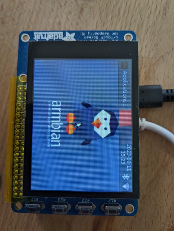
Yep so I got the Xorg running and it show the armbian screen but I have a similar error message in the Xorg.0.log as you got (==) FBDEV(0): Backing store enabled [ 199.430] (EE) FBDEV(0): FBIOPUTCMAP: Invalid argument For my bananapi the HDMI is deactivated if there is no cable on startup so my lcd display becomes fb0 maybe you are trying to start on the wrong device? But from here on I can only make some guesses since i have never before worked with Xorg (==) FBDEV(0): Backing store enabled [ 199.430] (EE) FBDEV(0): FBIOPUTCMAP: Invalid argument This seems not to cause any problem however connecting a mouse or a keyboard always fails. This is then probably related to the xorg config file which I created following the previously mentioned guide. Then I just execute sudo startxfce4 an I get the desktop on my display.
-
Don't do that it can cause you troubles with your spi, I also just learned that recently from Ryzer in the following post. Then why is your Chip Select (CS) connected to ground? Connect it to the Spi_Cs0 PC3 Pin 24. and then change Fragment@1 in the overlay to following: fragment@1 { target = <&spi0>; __overlay__ { /* needed to avoid dtc warning */ #address-cells = <1>; #size-cells = <0>; status="okay"; cs-gpios = <&pio 2 3 0>; num-chipselects = <1>; This should work with the OrangePi for the nano pi you need to check and change the pins. For example the spi_cs pin on the neo3 ist the B0 and on the orange pi it is the C3 so for the neo3 the line in the overlay should be: cs-gpios = <&pio 1 0 0>; The Pios for dc and reset need to be changed in a similar way as well since the neo3 doesn't have an A3 pin so maybe take A4 and A6. Maybe also the targeted spi needs to be changed since some boards don't use spi0 on the 40 header pins. Last but not least good luck with your display
-
Hi just had a similar problem with my bananapi and the ili9341 and might have some helpful tips. 1. thing I did was to check if there's a driver for your chip honestly I am not sure if this is the case for the ili9488 locate ili9488 2. Load your overlay and check dmesg dmesg | grep -E ili9488 There you should see if the panel gets loaded during spartup or if there are any problems with the spi bus for example. 3. Post your overlay and wiring, I had a lot of trouble too understand the syntax fot the <&pio x y z > and got them wrong all the time. the orange pi cs(chipselect) for the spi4 is the gpio1_c4 so it should look like this <&pio 2 4 0> With 2 = (letter C)-1 4(comes from the pin) and 0 is low. at least that's how it works with the bananapi. Hope this can help a little bit
-
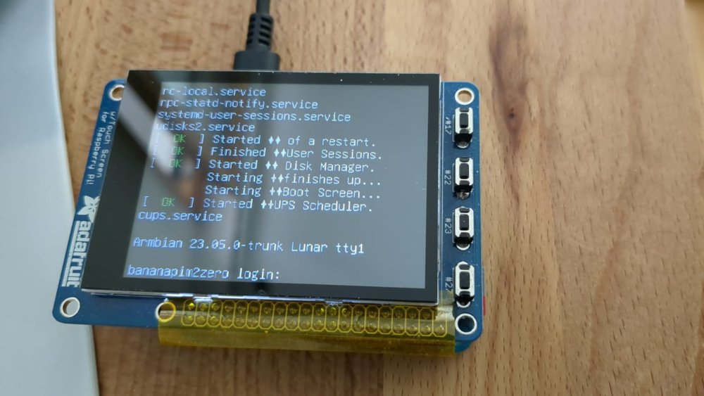
Finally it works or at least I can see the console here's the overlay I used sudo vim /boot/dtb/overlay/bananapitft.dts /dts-v1/; /plugin/; / { compatible = "allwinner,sun4i-a10", "allwinner,sun7i-a20", "allwinner,sun8i-h3", "allwinner,sun50i-a64", "allwinner,sun50i-h5"; fragmen@0 { target = <&pio>; __overlay__ { display_pins: display_pins { pins = "PC4", "PA2"; function = "gpio_out", "gpio_out"; }; }; }; fragment@1 { target = <&spi0>; __overlay__ { /* needed to avoid dtc warning */ #address-cells = <1>; #size-cells = <0>; status="okay"; cs-gpios = <&pio 2 3 0>; num-chipselects = <1>; display: display@0 { compatible = "adafruit,yx240qv29", "ilitek,ili9341"; reg = <0>; pinctrl-names = "default"; pinctrl-0 = <&display_pins>; spi-max-frequency = <8000000>; rotation= <270>; bgr = <0>; fps = <10>; buswidth = <8>; height = <240>; width = <320>; reset-gpios = <&pio 2 4 1>; /* GPIO 24 */ dc-gpios = <&pio 0 2 0>; /* GPIO 25 */ debug = <3>; }; }; }; __overrides__ { rotation = <&display>, "rotation:0"; fps = <&display>, "fps:0"; debug = <&display>, "debug:0"; }; }; I did a stupid copy paste mistake and targeted spi1 insead of spi0 also manually compiling the .dts gave me warnings that didn't show up while using the armbian-add-overlay maybe that makes a difference as well but right now I am too lasy to check that. Thank you all for your help wouldn't been able to do it without it :)))
-
Hello there Thx a lot for all the informations I am finally getting closer to really understand what I am doing and how everything is working. I manage to properly initalise my screen in the lastest armbian lunar version: dmesg | grep ili9341 [ 2.899560] panel-ilitek-ili9341 spi0.1: get optional vcc failed [ 2.908867] [drm] Initialized ili9341 1.0.0 20210716 for spi0.1 on minor 1 [ 3.746474] panel-ilitek-ili9341 spi0.1: [drm] Initialized display serial interface [ 3.969566] panel-ilitek-ili9341 spi0.1: [drm] fb0: ili9341drmfb frame buffer device Still no picture on the screen but personally a hugh success for me and a motivational boost I found a usfull link to a good description unfortunatly it is in german but I can translate it if needed. German Guide Spi lcd ili9431 I am using a different screen on from adafruit https://www.adafruit.com/product/2423 I took a look at the pcb and could Identify almost all the required pin appart from the reset pin and they are the same as this setup from the german guide: therefore I used the following code overlay and managed to at least initiate the display. /dts-v1/; /plugin/; / { compatible = "allwinner,sun4i-a10", "allwinner,sun7i-a20", "allwinner,sun8i-h3", "allwinner,sun50i-a64", "allwinner,sun50i-h5"; fragmen@0 { target = <&pio>; __overlay__ { display_pins: display_pins { pins = "PD4", "PC0"; function = "gpio_out", "gpio_out"; }; }; }; fragment@1 { target = <&spi1>; __overlay__ { /* needed to avoid dtc warning */ #address-cells = <1>; #size-cells = <0>; status="okay"; cs-gpios = <&pio 3 0 0>; num-chipselects = <1>; display: display@0 { compatible = "adafruit,yx240qv29", "ilitek,ili9341"; reg = <1>; pinctrl-names = "default"; pinctrl-0 = <&display_pins>; spi-max-frequency = <8000000>; rotation= <270>; bgr = <0>; fps = <10>; buswidth = <8>; height = <240>; width = <320>; reset-gpios = <&pio 3 4 1>; /* GPIO 24 */ dc-gpios = <&pio 2 0 0>; /* GPIO 25 */ debug = <3>; }; }; }; __overrides__ { rotation = <&display>, "rotation:0"; fps = <&display>, "fps:0"; debug = <&display>, "debug:0"; }; }; Lots of text and I hope it can help
-
Hey tried the same thing aswell on a bananapiM2 Armbian 23.05.0-trunk Lunar, kernel Linux 6.2.13. I'm not too good at coding so I just went ahead an copied most of the code for the overlay and the boot configuration. Running: lsmod |grep ili9341 results in the same as previously mentioned. lsmod | grep ili9341 ili9341 16384 0 panel_ilitek_ili9341 20480 0 drm_mipi_dbi 24576 2 ili9341,panel_ilitek_ili9341 However checking dmesg for the spi entires reveals that ther might be a problem with the used port : param_spidev_spi_bus=0 Running dmesg | grep spi results in the following: dmesg | grep spi [ 3.073618] sun8i-h3-pinctrl 1c20800.pinctrl: pin PC0 already requested by 1c68000.spi; cannot claim for spi0.1 [ 3.073657] sun8i-h3-pinctrl 1c20800.pinctrl: pin-64 (spi0.1) status -22 [ 3.073689] panel-ilitek-ili9341 spi0.1: Error applying setting, reverse things back [ 3.076126] sun8i-h3-pinctrl 1c20800.pinctrl: pin PC0 already requested by 1c68000.spi; cannot claim for spi0.1 [ 3.076166] sun8i-h3-pinctrl 1c20800.pinctrl: pin-64 (spi0.1) status -22 [ 3.076196] ili9341 spi0.1: Error applying setting, reverse things back So I think the problem lies in the selected spi bus rahter than in the code itself, since on start up the panel is reversed. Or do you have different opinion/idea?


