
Larry Bank
-
Posts
161 -
Joined
-
Last visited
Content Type
Forums
Store
Crowdfunding
Applications
Events
Raffles
Community Map
Posts posted by Larry Bank
-
-
Yes, the physical pins line up with the RPI original 26-pin GPIO. Remember that the connector is on the "other side" of the board with respect to the RPI way of doing it.
-
The MAX7219 can easily be driven with bit banging (see my Arduino implementation here: https://github.com/bitbank2/max7219), but you raise a good question. I don't see in the documentation how it would be possible to enable both SPI bus 0 and 1 on AllWinner boards using the device tree overlays text file.
@tkaiser Do you know how to specify both buses to be enabled?
-
I just published a simple C project to make use of the IR receiver (either on-board or connected to an arbitrary GPIO):
https://github.com/bitbank2/ir_receiver
It's basically the simplest C code to receive IR codes without the use of external libraries or kernel drivers. It depends on a reasonably accurate system clock. This works fine on Armbian running on OrangePi boards, but doesn't work on my RPI3B.
-
25 minutes ago, chwe said:
and otherwise, you can test ArmbianIO from @Larry Bank which is also based on sysFS but might be a bit more 'lightweight'.. Not sure, cause I didn't do 'benchmarking' and I don't know if somebody ever tried to get at it's limit..
CHWE's comments look to be correct. If you need super fast toggling of GPIOs, then you need to memory map the I/O ports and write directly to them. My ArmbianIO library and others use the sysfs access which goes through the linux file system (much slower).
-
I added GPIO interrupt callbacks to my ArmbianIO library (https://github.com/bitbank2/ArmbianIO)
It should be able to handle that frequency if you make the callback function simple (e.g. increment a counter).
-
55 minutes ago, vin7102 said:
Larry,
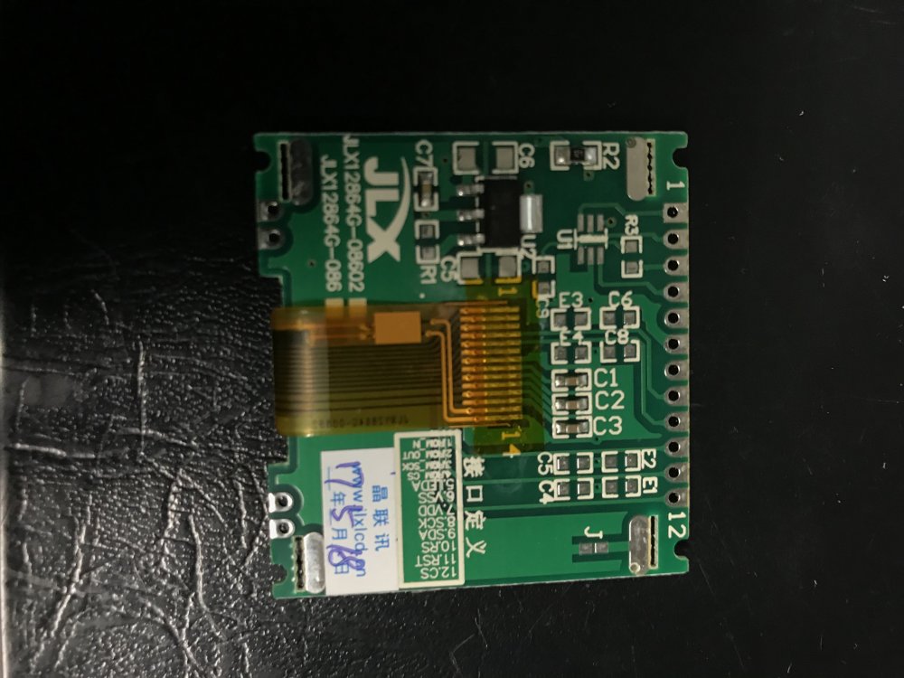
I just received my JLX12864G-08602 displays and was wondering if you would want to help me get this set up to work with my pro mini?
Maybe a simple sample Arduino sketch to demonstrate printing a variable and blanking the screen. I looked around the web and I haven't been able to find any examples or library's (or even a wiring diagram).
I would be more than happy to compensate you for your time for helping get this going.
Regards,
Vince
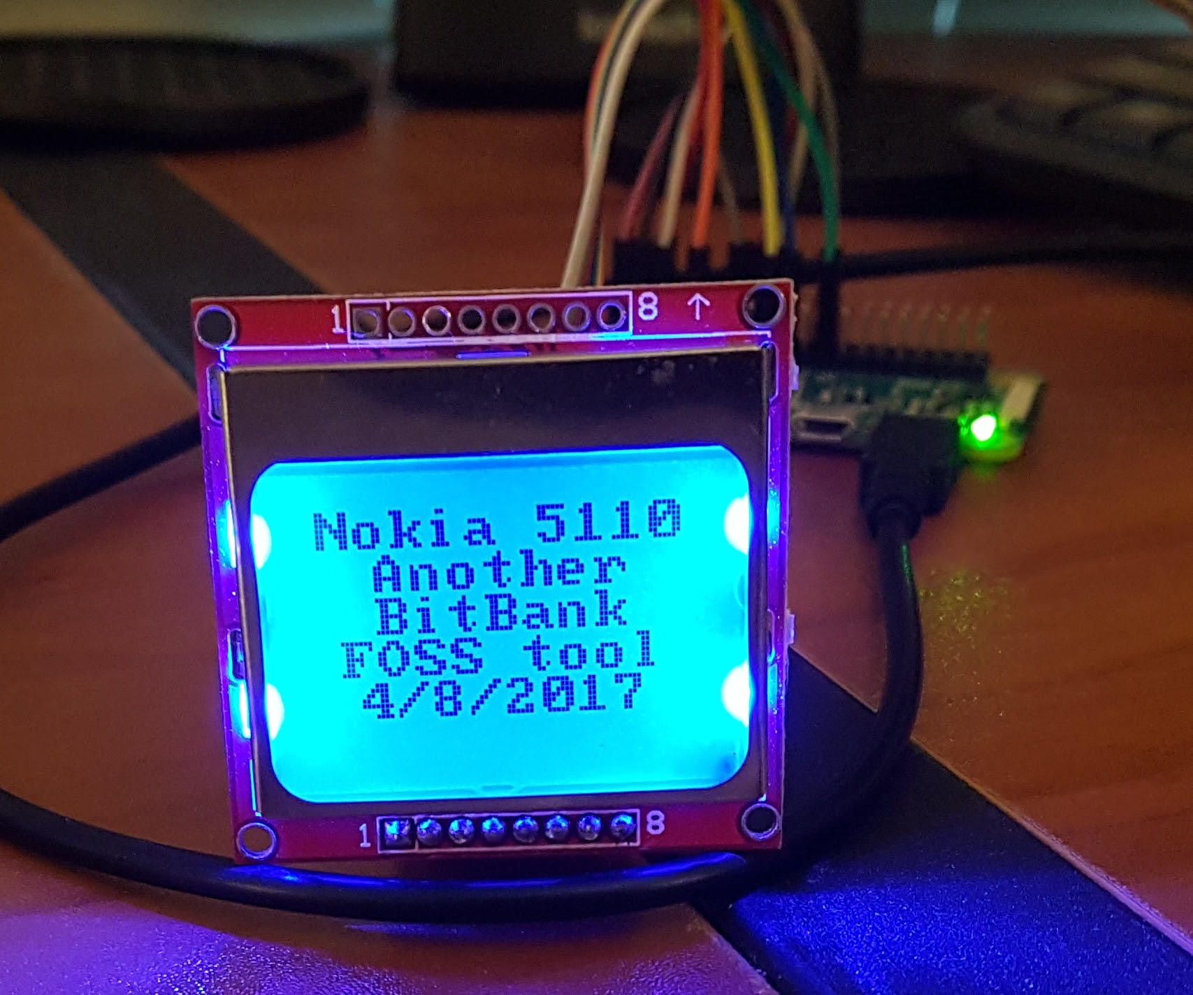
Hi Vince,
Your display luckily doesn't have the Chinese character rom, but does have the regulator. If you plan on powering this from 3 or 3.3V, then you can remove the regulator and bridge R1 with a blob of solder. No need to pay me, I shared a Linux and Arduino library to control the display here:
https://github.com/bitbank/uc1701
It's quite easy to get going on the Arduino. Your sketch will start like this:
#include <uc1701.h>


void setup()
{
   uc1701Init(DC_PIN, RESET_PIN, LED_PIN,  bFlip180, bInvert);
   uc1701Fill(0);
}

void loop()
{
   uc1701WriteString(0, 0, "Hello World!", false, FONT_NORMAL);
}
-
** Update **
I just added support to the ArmbianIO project for accessing the on-board IR receiver (connected to GPIO PL11 on many Orange Pi boards). Use the macro "IR_PIN" when reading the signal from the receiver (instead of specifying the header pin number). I will be releasing a demo app shortly which receives NEC ir codes without the use of the LIRC driver. My demo app will allow you to connect any IR receiver to any available GPIO pin or use the built-in one if present. The IR codes can be received with a simple 1-bit port without the use of a UART by simply timing the on/off signal to a reasonable margin of error using the Linux clock functions.
-
43 minutes ago, divis1969 said:
I've tried to install GitLab onto Banana PI running Armbian (Ubuntu 16.04 server).
I've followed the instructions for Raspberry PI (on https://docs.gitlab.com/omnibus/manual_install.html) and generic https://about.gitlab.com/installation/#ubuntu
Unfortunately this fails:
$curl -s https://packages.gitlab.com/install/repositories/gitlab/raspberry-pi2/script.deb.sh | sudo bash
...

$ sudo EXTERNAL_URL="http://myurl.com" apt-get install gitlab
...
Verifying we have all required libraries...
Could not find gem 'devise-two-factor (~> 2.0.0)' in any of the gem sources
listed in your Gemfile or available on this machine.
Did anybody tried the same? Is there any way to fix the issue?
I didn't even know they offered some kind of GUI. I use gitlab from the command line with the default git application and it works fine.
-
I wrote some C code to talk to the sense hat from Armbian. The display works fine and so do the sensors:
https://github.com/bitbank2/sense_hat_unchained
-
2 hours ago, martinayotte said:
Did you tried "i2cdetect" to see if the LCD is properly detected ?
BTW, as you've mentioned earlier, there are also some LCD that have SPI wires, make sure you are using the I2C instead, mode selection is probably determined by another pin.
If that wiring list is correct, then it indicates that the display is connected via SPI, not I2C. They sometimes label the MOSI line as SDA, but the presence of CS, DC and RST indicate that it's an SPI device.
-
32 minutes ago, vin7102 said:
Couple more questions here if you dont mind:
Do you use SPI displays?
What is the normal library used with Arduino for this display?
Is the library pretty nice to work with?
Is 30 FPS rate an average refresh rate for this type of display?
I have been on a mission to learn all I can about IoT (MCUs/displays/sensors/motors/etc). I buy inexpensive devices, read the datasheet, then write code to control them. I don't know about "normal" libraries because I always write my own. I haven't done extensive testing on the refresh rate of the monochrome LCDs, but I remember doing some brief experiments where I saw a decent refresh rate. I use SPI connected displays in several of my "experiments", both monochrome and color. I used to earn a living emulating classic games, so I've done a bunch of projects with color LCDs (SPI connected) to optimize performance/refresh. I'm looking for interesting projects to make with this knowledge. I recently designed a physical therapy device for a scoliosis doctor using this LCD display, an Arduino Pro Mini, accelerometer and light sensitive resistor (to turn on the backlight automatically when ambient light levels are low).
-
11 hours ago, vin7102 said:
Hello Larry,
I'm working on an Arduino proMini project that will require over 50 displays and this one here looks like it may be a good candidate, do you know if this particular display is still on the market for purchase?
If so, do you possibly have the tech specs of it handy?
Thanks
Vince
Yes, it's still available. It can be purchased with a PCB attached and through-hole connectors or just the raw display with a ribbon cable. I have only bought the PCB version. Single piece, they sell for about $4 each from China. I really like this display because it's super low power (275uA @ 3V) when active and has a nice even backlight that only consumes 4.8mA. The controller chip behaves much like every other LCD controller (even similar to the popular SSD1306 OLED displays). The refresh rate is pretty quick and I believe it's visible at > 30FPS. I just used this in a commercial project with a Pro Mini. It's my favorite LCD so far due to its low cost, low power and good contrast. If you search on AliExpress with the words "128x64 LCD COG" you'll see them.
-
58 minutes ago, bodtx said:
with something like this ?
Is there any known lib in C for that, it seems very manual.
thx for pointing to me that it was a linux classic.
Btw it is for controlling a 433 RF emitter
You found a reasonable example of how to initialize and control a serial port in Linux. I wrote similar code for one of my projects. I'm sure there are some libraries to simplify access, but I'm not familiar with them.
-
2 hours ago, bodtx said:
waooo, your lib is a great idea. I do not need a special compatibility with wiringPi, but I would like to drive a MCU with serial communication (more basic than spi or i2c), in your function available I don not see somtehing like this
The I2C and SPI support isn't needed since there are standard Linux interfaces. GPIO pins are the only oddity where the header pin can be connected to anything depending on the board manufacturer. Linux also supports serial ports with a standard interface, so it's not necessary to add it to my ArmbianIO project.
-
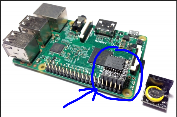
Do you specifically need WiringOP or do you just want a simple way to access GPIO? If the later, you can try my ArmbianIO library:
https://github.com/bitbank2/ArmbianIO
I created a new API interface that's much simpler to deal with. GPIO pins are referenced by physical pin number and this allows using all available GPIOs.
-
If you can find the pinout for that board's header, I'll add it
-
The sysfs driver should be loaded by default to access GPIOs. You can test it by running my ArmbianIO project:
https://github.com/bitbank2/ArmbianIO
-
Spoiler17 hours ago, guidol said:
but I dont like the soldered battery
 therefore I used the external module
 ") after disabling the charging circuit now with CR2032 Battery on the back.
after disabling the charging circuit now with CR2032 Battery on the back.
I did like the documentation at
https://www.raspberrypi-spy.co.uk/2015/05/adding-a-ds3231-real-time-clock-to-the-raspberry-pi/but it was for the RPi which has at that pins I2C-1 and the OPi and NanoPi has at this Pins I2C-0 connected...
So I used such commands:
i2c DS3231N Clock:
apt install i2c-tools
armbian-config: activate I2C-0
i2cdetect -y 0
(modprobe) rtc-ds1307  ==> /etc/modules

in /etc/rc.local:
echo ds1307 0x68 > /sys/class/i2c-adapter/i2c-0/new_device
hwclock -s

Once correct you can write the system date and time to the RTC module using :
sudo hwclock -w

You should be able to read the date and time back from the RTC using :
sudo date; hwclock -r

compare hwclock
sudo hwclock -c

NeoCore2 Mini Shield:
Number#	Name	Number#	Name
1	SYS_3.3V		2	VDD_5V
3	I2C0_SDA / GPIOA12	4	VDD_5V
5	I2C0_SCL / GPIOA11	6	GND

https://www.raspberrypi-spy.co.uk/2015/05/adding-a-ds3231-real-time-clock-to-the-raspberry-pi/
https://manpages.debian.org/stretch/manpages-de/hwclock.8.de.html
https://www.youtube.com/watch?v=ND2shVqV9s4

echo "Updating time via ntp from ptbtime3.pt.de"
ntpdate -q ptbtime3.ptb.de
echo "writing actual time to hwclock..."
hwclock -w
echo "reading actual time from hwclock..."
date; hwclock -r
It's not a battery soldered on to that small module, it's a tiny supercapacitor
-
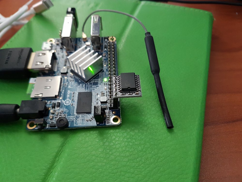
33 minutes ago, MarshallMCH said:
Hi all, I'm looking to connect a DS3231 battery-backed RTC to my OPI PC Plus, and I want to confirm I'm connecting it properly. Here's an image of a Raspberry Pi with the module I'm using (I'm assuming the GPIO is the same config as my OPI). Is this correct? I'm not seeing the eeprom at address 57 when using i2cdetect.
Yes, those little modules are great; they don't contain any EEPROM, that's why the address isn't visible. Just note the direction of the header on your OrangePi PC Plus. I couldn't find the info for your board, but for my Orange Pi Lite, the header is "backwards"
-
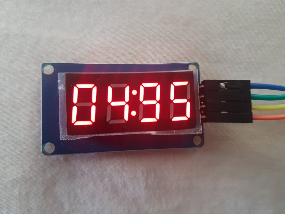
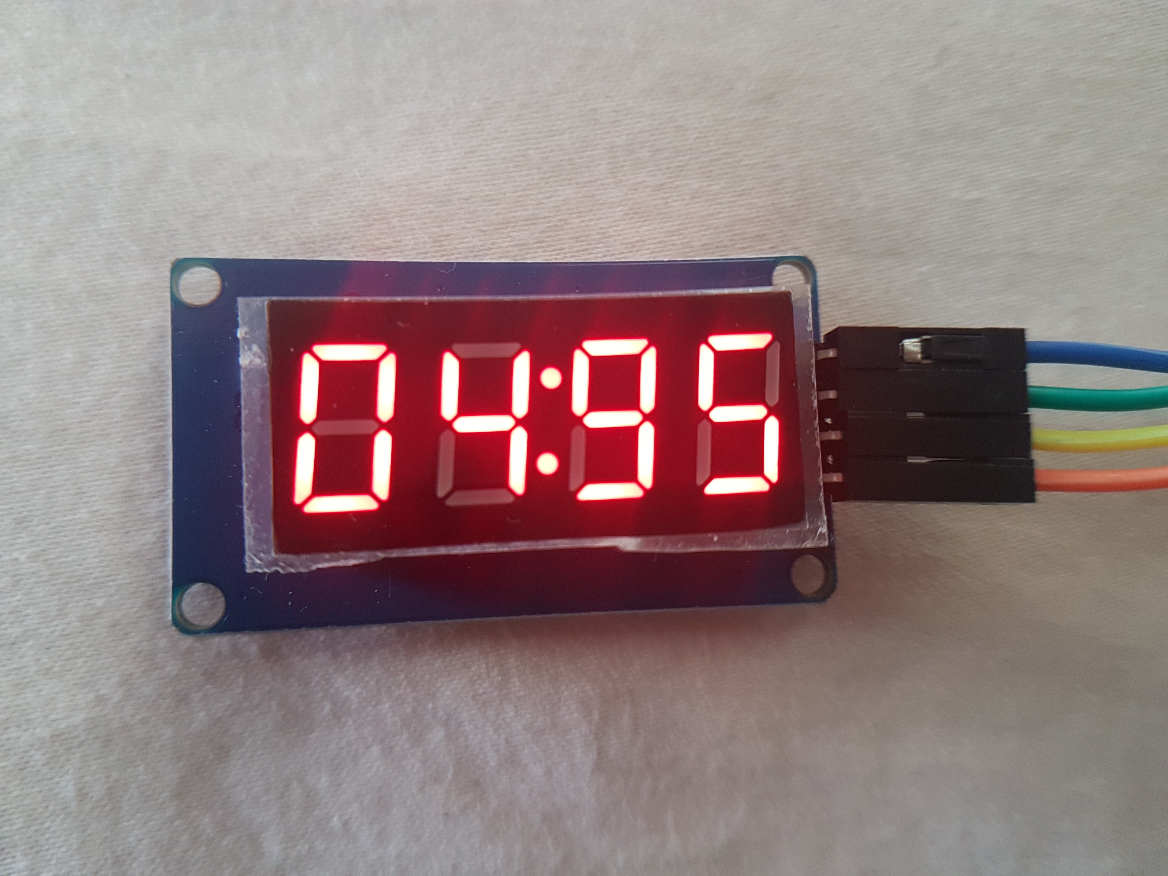
I just released a new C library for communicating with those inexpensive 4-digit 7-segment LED displays:
https://github.com/bitbank2/tm1637
They can run on 3.3V or 5V and draw between 1 and 15mA depending on the brightness setting. I purchased mine from an AliExpress vendor for 68 cents each with free shipping.
They use a custom 2-wire communications protocol and must be "bit-banged" from 2 GPIO pins. In my demo, I assign pins 38 and 40 on my Orange Pi Lite.
-
On 1/24/2017 at 11:26 AM, peter12 said:
hi there, please, I have orange pi lite and using spi to control ws2812b. My problem is, that firs led is green (when other are off), when I set all to blue first led is blue too, when all to green first is green, when all to red first is yellow. Any idea what is causing this issue?
Or any idea how to leave first LED off completely rather than being green? Thanks.
UPDATE: I found out GREEN is always in up (turned on) state for first LED in strip. So according to my opinion, final last data are somehow corrupted and therefore green part of first led is in "ON" state.
Did you ever find a solution to this? I'm trying to control NeoPixels from an Orange Pi Lite and I'm seeing the same issue. The first LED being green means the problem is occurring at the beginning of the data stream, not the end.
P.S. I've been soldering together individual ones and I've found a few bad ones. Not sure if I fried them from too much heat or they were defective.
-
Looks like there are a bunch of potential problems with that code. I see some commented out lines which hardcode the SPI bus number as 1. On the Orange Pi Zero (and most H2/H3 boards), the header exposes SPI bus 0. Other issues are in the spi_read() function, it looks like it's trying to do an asymmetrical number of bytes of writing versus reading. That will potentially cause odd behavior in the driver since SPI reads/writes simultaneously the same number of bytes. In other words, if you shift out 1 byte, you only read back 1 byte. Why not start from a simpler set of code (e.g. my ArmbianIO project)?
-
It's hard to diagnose without seeing your code. The default max SPI speed is 33Mhz, so that shouldn't be a limiting factor. Which model Raspberry Pi?
-
6 hours ago, Igor said:
Thanks for mentioning that @Igor, I share a lot of code, but rarely get any feedback that people are using it.


Display ili9341 on H5
in Off-topic
Posted
Depends on what you mean by succeeded. My SPI_LCD project runs fine on Armbian supported boards (including H5), but it doesn't create a framebuffer. It's a user-level program which talks directly to the LCD and allows you to draw text and graphics with a simple API:
https://github.com/bitbank2/SPI_LCD
Even if your project needs fbtft, my code is useful to see if your wiring + display are working correctly.