-
Posts
16 -
Joined
-
Last visited
Recent Profile Visitors
1052 profile views
-
Good job! Didn't expect V1.4 to work but that's awesome! Next up is just getting it to run the 24 bits that it support. I also got myself an Orange pi One where i am stock at the 48KHz @ 16 Bit
-
As mentioned in my last comment it is not possible to get I2S to work on the newer boards
-
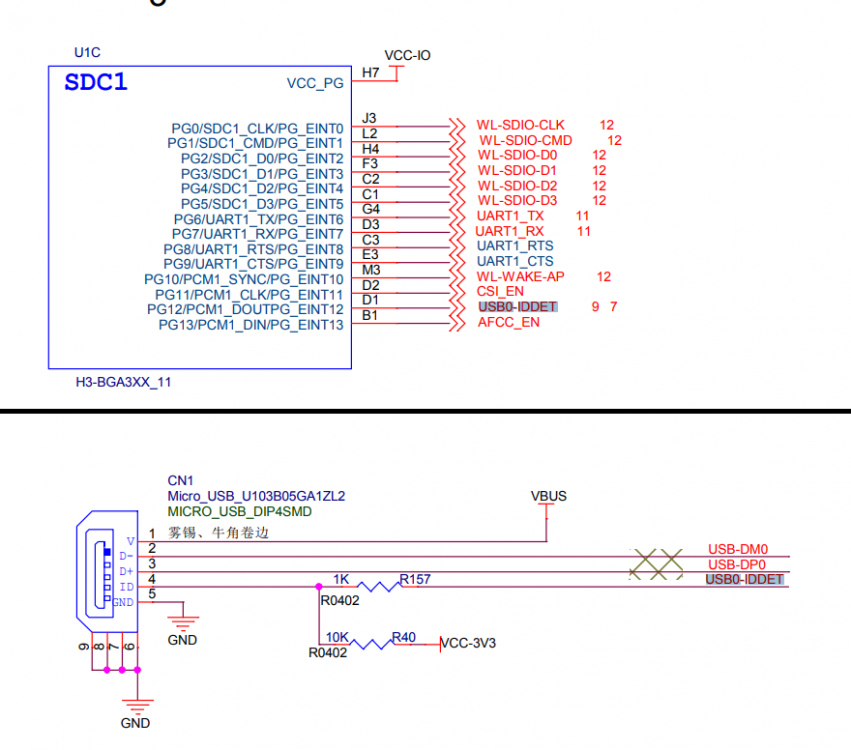
So time for a sad update.. About I2s on the newer boards I thought that the I2s was placed on a single bus with more outputs but they are on seperate buses so that means to use PCM1 we'll have to have access to 2 other GPIO's where one of them is unused so we cannot access it, that GPIO is PG11 aka CSI_EN and it is not descriped where it goes anywhere in the diagram so i cannot rework anything.. GODAMMIT WE WERE SO CLOSE... MAN i swear the designers of the Orange pi's really kills the idea of overruling Reaspberry PI.. They really need some proper designers to tell them what could make their boards awesome Oh well it is 1000 times simpler to do on a Orange pi One, it is almost plug and play!
-
And i just realized the resistor is on my own, currently just creating an Armbian from the start to make sure everything goes simple for me Removed the resistor and the leg on the resistor where the GPIO is placed is "B" if i refer back to your drawing;
-
I will try to be better at checking my account here so we can get to solve this, kinda exited to see what results we might get!
-
I know i know, it is written in the diagram, but i wanna know which exact leg is connected to R40 and which exact is connected to the GPIO so i can make some documentation about If you look at the picture where you wrote a,b,c,d and so on each pad, can you tell me which pad is NOT connected to R40, that leg is the GPIO which you need to solder a wire to
-
Can you measure which leg at R157 is connected to 3v3?; Leg A or B?
-
Exactly! The reason is for not having a connection to the USB plug
-
Good job mate! Now it is just about finding out where things are connected, it sadly requires a multimeter next step. Above R157 there is a resistor called R40, to find out which leg we'll use as data out for the DAC you'll have to measure which pad of the two resistors have a connection, as seen on the USB plug R40 puts R157 to 3.3v. When you know which pad is 3.3v please inform me and next step would be to remove R157 and solder a wire to it so you can connect it to your DAC.. Man i wish i had a newer board so i could try it out..
-
Hello, sorry it is long time since i have been active https://www.aliexpress.com/item/Interface-I2S-PCM5102-DAC-Decoder-GY-PCM5102-I2S-Player-Module-For-Raspberry-Pi-pHAT-Format-Board/32833996405.html?spm=2114.search0104.3.20.749c3092lsgAgP&ws_ab_test=searchweb0_0,searchweb201602_2_10152_10151_10065_10344_10068_10342_10343_10340_10341_10084_10083_10618_10630_10304_10307_10302_5722317_5711211_10313_10059_10534_100031_10629_10103_10626_10625_10624_10623_10622_10621_10620_10142,searchweb201603_25,ppcSwitch_3&algo_expid=433dce46-a79f-4428-b62b-90f0fc5620f0-3&algo_pvid=433dce46-a79f-4428-b62b-90f0fc5620f0&transAbTest=ae803_5&priceBeautifyAB=0 This one
-
Hmm.. Not alot to work with sadly, if i had it here i would be able to find the resistor but it is a bit hard. It is called R157 and is a part of the other data bus so you could use that instead
-
Can you do me a favor and take another picture of the backside?
-
Oh.. I see, i will look into that for you Edit: Oh man.. hey completely removed that resistor and the access to the PA20 after version 1.1. What you can do tho is modifying the USB_detect for CN1(The micro usb). It has a 1K resistor but as the Schematics for version 1.4 is not available unless hidden somewhere. I will have to look into that mod and have a look at it!
-
Still working on increasing the frequency to 192KHz and 32 sample resolution as the Datasheet of the H3 says it support. I might need to get my hands on some audio files that support the maximum output to test it. I am currently using mpg123 to play the audio but not sure about it it has limits..
-
And to change the default output device: Do the following open asound nano /etc/asound.conf Add the following code pcm.!default { type hw card 1 } and save, no need to restart You have now a full functional DAC to your OPI Zero


