


5kft
-
Posts
264 -
Joined
-
Last visited
Content Type
Forums
Store
Crowdfunding
Applications
Events
Raffles
Community Map
Posts posted by 5kft
-
-
Indeed, this is strange... Perhaps it's just not worth it to do the mod - it's still not clear why Xunlong doesn't stuff this part. Perhaps this power circuit is too unreliable with their H5-based boards?
-
2 hours ago, km1kze said:
.. I have on all 5v pins something like 4.2v ...
Might this possibly be due to the power adapter you are using...? I just checked several of my modified boards and they all measure 5v on the 5v rails, and USB devices have been working fine for me with the Orange Pi expansion adapter. As a test, I just plugged in an external USB SSD drive (powered via the USB port) and it was detected and works fine (and the 5v rail still measured 5v).
As has been noted many times elsewhere in these forums, it's very important to use only high quality 5V USB power adapters with these boards. I've had good luck with FriendlyElec's 5V 3A Universal USB Port Power Adapter, as well as some 5V 2A adapters I purchased in the past.
-
3 hours ago, km1kze said:
The mosfets arrived and finaly managed to make a test, and it works! Thank you again 5kft !
km1kze, this is great news - I am very glad to hear this!!
")
-
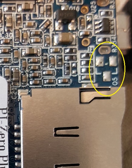
5 minutes ago, Jota79 said:
Please... Could someone to take a photo of BSN20 MOSFET in te PCB? I would like to check my Orange Pi Zero Plus 2.
Thanks in advance
Sure, here's a pic showing the context - the location of Q5 is right next to the uSD slot on the underside of the board:
-
12 hours ago, Igor said:Quote
as your suggestion, should we change the Q5 into BSN20 MOSFET?Or should we just leave the possition of Q5 empty?
I'm not sure why they wouldn't stuff the BSN20 MOSFET into Q5, given that it does enable the use of higher frequencies. So in my opinion they should definitely include it. However zador is completely correct: if they change this then they need to increase the version number of the boards (both the H5 Plus2 and Plus). The default for Armbian should be the lower (safe) clock speed for 1.1v to work with all board revisions, and the higher speed could be enabled per an overlay as previously noted (if the user has a modified or new board).
-
15 minutes ago, tkaiser said:
Agreed!
I like this as well - very clean/simple. By default the device will work reliably, and if someone wants to increase the clocks they can easily do so and it will "just work" (assuming that their board H/W actually supports the higher clock rate).
-
9 minutes ago, tkaiser said:
Ok, then let's assume voltage regulation simply never worked on the Orange Pi H5 boards with SY8113B, right? Which would mean we should rather sooner than later limit them to 912 MHz max cpufreq... (or even 816 MHz to have some safety headroom?)
I was going to suggest this. With this part missing the board is basically locked at running at 1.1v.
-
Just now, Igor said:
Both are ok but before the file was missing ... I don't know if it is related, but we had a short blackout on the main internet connection right around the time of the initial post.OK, thanks Igor!
-
2 minutes ago, km1kze said:
Thank you again, but I can't download the attached file, it seems it may not be properly uploaded. Can you please reupload it?
I've attached it here as a zip file, hopefully that will work
-
I very much hope that those BSN20s will work - I bought mine from that very same seller
Regarding increasing the clocks, I've attached a subset of my test patchset for the current mainline sunxi-next kernel (4.14.y) that you could start from. Hopefully you should be able to just copy this to your "armbian/build/userpatches/kernel/sunxi-next/" directory, then build your kernel as normal (e.g., "./compile.sh KERNEL_ONLY=yes KERNEL_CONFIGURE=no KERNEL_KEEP_CONFIG=no BRANCH=next BETA=yes BUILD_KSRC=no BOARD=orangepizeroplus2-h5"). Note that you'll need to update your "/etc/default/cpufrequtils" configuration to set the new min/max speeds (don't forget to reboot or restart the cpufreq daemon after doing this).
When you do the build, make sure the patch step succeeds - the "z" at the beginning of the filename helps ensure that it is the last patch applied.
(Note also that on reboot the HDMI driver crashes on my Plus2 - as a temporary workaround I disabled HDMI in the DTS as well. Also I noticed that the default Armbian OPi plus2 patchset adds the regulator entry - I was confusing this change with my Neo Plus2 patch for this.)
-
Glad to help! Yes, the photos on Xunlong's site show the part being present, but on both my Zero Plus2 and my Zero Plus (also an H5-based device) this single part is missing. I've been running my fixed version of my Plus2 (where I soldered a BSN20 onto the missing spot) since my last post, and it's been working wonderfully!
As I noted previously, I updated the appropriate sun50i-h5* DTS files and added the regulator setting, updated the cpu_opp_table to include the increased clock frequencies, and updated the thermal cooling-maps and it clocks to 1.296GHz perfectly (and downclocks when the temps get too high). I've been hammering the board over this past week to test stability, and it works great - zero crashes.
test@orangepizeroplus2:~$ cpufreq-info -c 1
cpufrequtils 008: cpufreq-info (C) Dominik Brodowski 2004-2009
Report errors and bugs to cpufreq@vger.kernel.org, please.
analyzing CPU 1:
  driver: cpufreq-dt
  CPUs which run at the same hardware frequency: 0 1 2 3
  CPUs which need to have their frequency coordinated by software: 0 1 2 3
  maximum transition latency: 6.24 ms.
  hardware limits: 240 MHz - 1.30 GHz
  available frequency steps: 240 MHz, 408 MHz, 648 MHz, 816 MHz, 912 MHz, 960 MHz, 1.01 GHz, 1.06 GHz, 1.10 GHz, 1.15 GHz, 1.25 GHz, 1.30 GHz
  available cpufreq governors: conservative, userspace, powersave, ondemand, performance, schedutil
  current policy: frequency should be within 240 MHz and 1.30 GHz.
                  The governor "ondemand" may decide which speed to use
                  within this range.
  current CPU frequency is 1.30 GHz.
  cpufreq stats: 240 MHz:88.52%, 408 MHz:3.58%, 648 MHz:0.00%, 816 MHz:0.00%, 912 MHz:0.00%, 960 MHz:0.00%, 1.01 GHz:0.00%, 1.06 GHz:0.00%, 1.10 GHz:0.00%, 1.15 GHz:0.00%, 1.25 GHz:0.00%, 1.30 GHz:7.89%  (28476)
test@orangepizeroplus2:~$
test@orangepizeroplus2:~$ sysbench --num-threads=4 --test=cpu --cpu-max-prime=20000 --validate run
sysbench 0.4.12:  multi-threaded system evaluation benchmark

Running the test with following options:
Number of threads: 4
Additional request validation enabled.


Doing CPU performance benchmark

Threads started!
Done.

Maximum prime number checked in CPU test: 20000


Test execution summary:
    total time:                          6.9850s
    total number of events:              10000
    total time taken by event execution: 27.9254
    per-request statistics:
         min:                                  2.79ms
         avg:                                  2.79ms
         max:                                  6.15ms
         approx.  95 percentile:               2.79ms

Threads fairness:
    events (avg/stddev):           2500.0000/1.22
    execution time (avg/stddev):   6.9813/0.00

test@orangepizeroplus2:~$
test@orangepizeroplus2:~$ cat /sys/class/thermal/thermal_zone0/temp
31339
test@orangepizeroplus2:~$
This simple fix really makes the Plus2 an incredibly useful board - just $20, super fast, built in eMMC, etc.! It is unfortunate, however, as without this modification these boards are basically maxed at 816MHz (seemingly the safe peak for 1.1v CPU voltage).
Interestingly, all my Orange Pi H3-based devices do include this part. It's just the H5-based ones that do not (but all the other power circuit parts are present). Perhaps this is a quick workaround that Xunlong did to address potential thermal issues or something (?).
I ordered a number of BSN20 SOT23-3s as well as some more Plus2s, and will be doing a bit of soldering when they all arrive...!
-
I recently purchased a number of Orange Pi and Nano Pi boards, and discovered the awesome work of the Armbian team :-) The Orange Pi Plus2 H5 is a rather nice board - built in eMMC, H5, etc. (I wish it had 1GB of RAM but that's a different subject.) I'd love to use these boards for a number of projects.
As a test, I modified the DTS for the board (mainline kernel) to enable support for the 1.1v/1.3v switch for VDD-CPUX using the SY8113B on the board. I also enabled the allowed clock changes to 1.2GHz for cpufreq. All of this worked great, but the board was very unstable at anything over 1GHz, which seemed strange, given that the CPU voltage should be switching to 1.3v.
I found that when measuring the voltage of the "1V2C" testpoint on the board that VDD-CPUX was always at 1.1v - it never switched to 1.3v. I did some further examination of the board, and I was surprised to find that the "Q5" BSN20 MOSFET was not populated on the board! I checked all of the other passives and they are present - it is like Xunlong simply decided not to stuff this part when they built the board.
So, as a test, I desoldered this part from my Orange Pi Zero rev 1.4 board and soldered it in the missing "Q5" spot on my Orange Pi Zero Plus2 board. And now it works great! VDD-CPUX properly switches between 1.1v/1.3v (measured at the "1V2C" TP), and I can clock the board to 1.296GHz without any problems.
Would anyone have an idea why Xunlong doesn't solder this part on the board by default? They include all the other parts in this part of the power circuit, just not this MOSFET. I was going to buy a few more of these boards, and I'd like to be able to clock them up. Perhaps I should just order a set of these BSN20 MOSFETs and solder them on myself when I receive the boards...?
Or perhaps I should just forget Xunlong/Orange Pi and use Nano Pis? My Nano Pi Neo Plus2 has been working perfectly since I powered it up (I enabled clocking to 1.296GHz by default as well in the DTS). By the way, I did some extensive tests and it looks like with both of these boards DVFS and thermal throttling works fine - the clock throttles back properly at the different temperature thresholds.
Thank you!
Orange Pi Zero Plus2 H5 hardware oddity in VDD_CPUX power circuit
in Allwinner sunxi
Posted
@guidol - re: /sys/class/leds: if it might be helpful to you, I've added DT support for the OPi Zero Plus2 H5 LEDs to my local Armbian builds; see https://github.com/5kft/build/blob/master/patch/kernel/sunxi-next/update-H5-board-config-support.patch, and search for "sun50i-h5-orangepi-zero-plus2.dts" in the patch file.