

going
-
Posts
511 -
Joined
-
Last visited
Content Type
Forums
Store
Crowdfunding
Applications
Events
Raffles
Community Map
Posts posted by going
-
-
08.10.2023 в 17:51, JF002 сказал:
As you can see, I would like to build Megi's kernel (https://xff.cz/git/linux/log/?h=orange-pi-6.5). The kernel tree is not available on Github or Gitlab, and is only available using Git bundles.
So, to build the kernel, I need to clone torvalds/linux, then apply the Git bundle file from Megi.
Does Armbian support this way of fetching the kernel sources? Is there another similar board I could use as inspiration?
If you use this instruction, you will get branches in the repository named:
megi/orange-pi-6.4
megi/orange-pi-6.5
megi/orange-pi-6.6These branches are the result of combining 27 branches with the corresponding branch kernel.org the repository.
If you extract one of these branches to the working directory and extract the difference as a series of patches with
the command "git format-patch v6.5.7..HEAD -o /path/to/tmpdir" you will get more than 600 files.
These patch files are already available in the build system.
All megi patches in tree patch/kernel/archive/sunxi-6.5/series.megous
But only those necessary for sunxi are used.
The minus (-) sign in the first position indicates that the patch file is not applied and does not adapt to the current version.Copy the patches.megous folder and the series.megous file somewhere, for example:
mkdir -p patch/kernel/archive/megi-6.5
cp patch/kernel/archive/sunxi-6.5/series.megous patch/kernel/archive/megi-6.5/
cp -r patch/kernel/archive/sunxi-6.5/patches.megous patch/kernel/archive/megi-6.5/
cp patch/kernel/archive/megi-6.5/series.megous patch/kernel/archive/megi-6.5/series.conf
Delete all minus (-) signs in the patch/kernel/archive/megi-6.5/series.conf file.
After that, you have to adapt the patches to the current kernel version yourself.
Apply them to the git repository as the "git am" command in the sequence order in the series file.When the work is finished and all the patches are applied, you will be able to extract them using a mk_format_patch script.
Specify an existing patch/kernel/archive/megi-6.5/patches.megous folder to extract.
The changed patches will be replaced.
P.S. All other questions please in a personal conversation.
-
1 час назад, TDCroPower сказал:
strange only that also an update from OMV fails.
"OMV" is strictly tied to the Debian distribution version. This is written in the documentation.
https://docs.openmediavault.org/en/6.x/releases.html#releases
-
11 часов назад, Gro-Tsen сказал:
5.10.160-S5279-D6ad0-P0000-C42aaHfe66-HK01ba-Vc222-Bc698-R448aSo I guess my question is what these numbers mean and how I can use them to reconstruct the exact kernel tree (or at least check that I have the right kernel tree). None of them seems to be a Git commit number, so I don't know what they are.
Please don't make sense of it. Take care of your health.
Just build the kernel with your configuration. Developer-Guide_Build-Preparation/#executing-any-bash-statement
If you need to make kernel debugging symbols or utilities, you will have to abandon the build system and build the kernel in the traditional way.
-
11 часов назад, TDCroPower сказал:
in the second test I started again with the image Armbian_21.08.2_Helios64_bullseye_current_5.10.63.img.xz and only updated the armbian-config with "apt update && apt install --only-upgrade armbian-config" so that it installs OMV 6 instead of 5.
Again, the system crashes in a similar area as test 1.I pulled out all three WD hard drives during testing.
The question remains, is the OMV installation currently incompatible for armbian?
I am not an expert on "OMV". Sorry.
installation/on_debian - Use this documentation if "armbian-config" fails.
-
04.10.2023 в 00:17, TDCroPower сказал:
thanks for the tutorial, i used /dev/sda1 in step 4 as it is my m.2 ssd partition.
Was that not correct?The key here is to mount the system folders /dev, /sys, /proc and enter the chroot environment using the chroot command.
Mount the disk you need. If there is a separate boot partition, mount it in the /mnt/system/boot folder as well.
Then these commands:root@helios64:~# mount --bind /sys /mnt/system/sys root@helios64:~# mount --bind /proc /mnt/system/proc root@helios64:~# mount --bind /dev /mnt/system/dev root@helios64:~# mount --bind /dev/pts /mnt/system/dev/pts root@helios64:~# chroot /mnt/system/As a result, you will get a full command prompt with superuser rights and any system commands for you will be executed correctly.
Update the apt cache.
Install, reinstall the packages, including the headers of the new\other kernel.
Enable or disable system services.
Recompile your custom applications.....
-
Alternatively, you can use a driver to emulate SPI on free pins (spi-gpio), if this driver is available in the kernel.
This is a slow driver. But complete freedom.
-
11 часов назад, Gunjan Gupta сказал:
@Peter GregoryAre you sure you are using the right pins? Based on the schematics, SPI1
@Gunjan Gupta You are, as always, the very courtesy!
Provided a link to the documentation.
From which follows: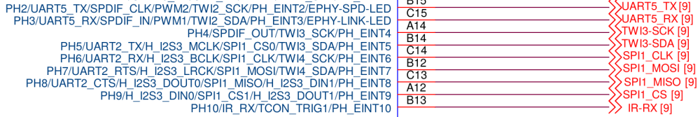
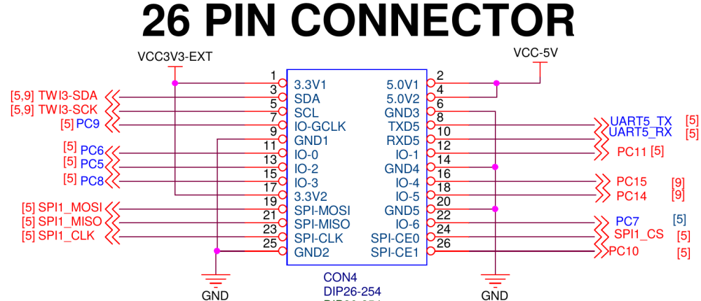
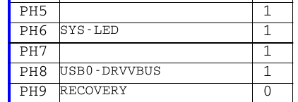
26 pins | pin name | function  |
-------------------------------|
  3     |    PH5   | spi1-cs0 ?|
 19     |    PH7   | spi1-mosi |
 21     |    PH8   | spi1-miso |
 23     |    PH6   | spi1-clk  |
 24     |    PH9   | spi1-cs0 ?|
 26     |    PC10  | spi1-cs1  |
-------------------------------
But this scheme says that the pins are divorced somewhere else. GPIO ASSIGNMENT (4)
The first thing that came to my mind was to take a soldering iron in my hands and .....
-
10 часов назад, TDCroPower сказал:
I am not quite sure if I can use my instructions from back then for the problem.
Is this variant correct to change the kernel?
If so which one is best to use?The fourth point should look like this:
4.
$ sudo su
root@helios64:~# mkdir -p /mnt/system
root@helios64:~# mount /dev/mmcblk2p1 /mnt/system

root@helios64:~# mount --bind /sys /mnt/system/sys
root@helios64:~# mount --bind /proc /mnt/system/proc
root@helios64:~# mount --bind /dev /mnt/system/dev
root@helios64:~# mount --bind /dev/pts /mnt/system/dev/pts

root@helios64:~# chroot /mnt/system/
....                            ## install, reinstall
~# exit                         ## exit "chroot"
~# umount /mnt/system/dev/pts
~# umount /mnt/system/dev
~# umount /mnt/system/proc
~# umount /mnt/system/sys
~# exit                         ## exit "root user"
If I understood correctly, booting from the system disk leads to periodic failure and reboot.
But loading from the SD card does not lead to such an effect? It is important. Please confirm or refute.
When loading occurs from the SD card, your raid array is not connected.
The disks were just determined and they are mounted as /dev/*.
The system does not access them (does not read or write). Energy consumption is at a minimum level.
When booting occurs from:27.09.2023 в 22:30, TDCroPower сказал:the system runs on an installed M.2 SSD on slot 1.
4TB WD Reds are installed in slots 2, 3 and 5.there may be short-term drawdowns of the supply voltage that lead to short-term inactivity of some chips
(resetting the clock, failure of the hard disk controller ....). Your operating system at the time of reading or
writing to the disk at the same time may be in the past or cannot read from the disk and as a result,
the failure stack is printed, each time different.
Fault repair:
1) Replace the watch battery on the board.
2) Open the power supply and look at the date of manufacture of the electrolytic capacitors of the output stage (they are the largest barrels in size).
If the age is more than 5 years, replace them with new ones. -
14 часов назад, Peter Gregory сказал:
How do you allocate header pins for another use?
orange-pi-pc-hdmi-lcd-mpi3508-touchscreen-spi-move-cs-from-pin-24-to-pin-22
You have just set up this touchscreen display for another device. This is a fact.
See the schematic diagram for this new device.
Perhaps SPI1 is already divorced on the board and connected to the memory chip?
Use my suggestions and do it by analogy. I'm sure you can handle it.
-
11 часов назад, TDCroPower сказал:
Unfortunately, I have no knowledge of how to do that.
Do you have something ready for me?I always have advice for such a case.
Download an image with an early kernel or\and later.Write it to the SD card and boot from it.
If the operation of the device is stable, you will be able to mount your root partition from which the device is usually loaded
and in the chroot environment you will be able to reinstall a stable kernel that you have tested.
-
18 часов назад, TDCroPower сказал:
edit:
the first failed start...
edit2:
another failed start, but with verbository = 7...
and after rebooting a good start...
and after a few minutes a crash and reboot...
An ambiguous situation. I wouldn't deal with this core. Today v6.1.55.
Try to build this version yourself.
You must first check the correctness of the application of patches. -
27.09.2023 в 22:30, TDCroPower сказал:
does anyone have an idea where I can start looking for the error?
Information on your screen. But I can't read it. Something in the core.
-
2 часа назад, DenisS сказал:
spi0_cs0_pi_pin: spi0-cs0-pi-pin {
pins = "PC3";
function = "spi0";
};spi0_cs1_pi_pin: spi0-cs1-pi-pin {
pins = "PG8";
function = "spi0";function = "gpio_out";
-
25.09.2023 в 01:58, Peter Gregory сказал:
[ 9.424199] ads7846: probe of spi0.1 failed with error -22
Look very carefully at fragments 1,2,3. It can be only one fragment0, which does not use the same pins (PA7 PC7) to describe different functions.
In a couple of days, my screen will reach the nearest post office.
I will be able to test it on a real stand and describe step by step how to connect three devices to one SPI.
-
If I understood this code correctly,
drivers/input/touchscreen/ads7846.c#L985
which returns your error, it believes that the touch is not connected. This pin must be configured <1> gpio active low.
When the touch of the display is connected, there should be a voltage on the IRQ pin and when a touch occurs,the touch lowers the voltage, thereby signaling an event.
-
15 часов назад, Peter Gregory сказал:
[ 7.220557] ads7846 spi0.1: failed to request pendown GPIO
[ 7.220570] ads7846: probe of spi0.1 failed with error -2Will you be able to photograph a section of the printed circuit board. Where is the chip soldered and the tracks that are connected to the pins?
-
4 часа назад, lalakii is сказал:
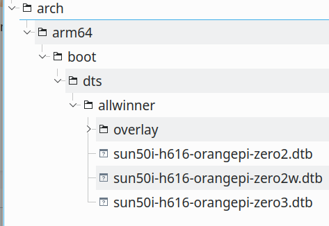
Since I didn't find an actively maintained kernel branch (for orangepizero3),
@lalakii is In Armbian for chips, allwinner uses only a branch with kernel.org . There is no special branch for a separate chip.
There is a series of patches that were taken from different places or made by different users and added to the series file.
The binary files that you kindly provided are useless for the build system.
Links to download from Google drive are also not useful.
All you need is to apply a series of patches to the corresponding kernel branch as a "git am" command.
Then make your comments on top with explanations and an indication of the author. Then extract these last commits using a script.cp armbian/build/tools/mk_format_patch $USER/bin; chmod +x $USER/bin mkdir -p $USER/tmpwork/patches.armbian cd /path/to/linux-stable mk_format_patch . HEAD~7..HEAD $USER/tmpwork/patches.armbianI think that you have guessed where they need to be placed, make a commit in the build system itself and make a pull request.
-
13 минут назад, lalakii is сказал:
dtbs fixed!
Usually provide a difference file.
Please, if you want to share the results of your work, make a set of patches as the output of the "git format-patch" command.Or a more time-consuming but faster way to make a pull request directly to the project on github.
-
5 часов назад, KREYREN сказал:
providing images for arm, but now we do riscv and even amd64 so i propose a rename
Only after the "Apple" is renamed. It has nothing to do with the production of agricultural products.
-
7 часов назад, Peter Gregory сказал:
pinctrl-0 = <&spi0_cs0_pin>;
In your version of the dts overlay, this pin is not described.
In this case, you must explicitly register it here.7 часов назад, Peter Gregory сказал:The display doesn't light up, and I don't see a new frame buffer /dev/fb1 for the LCD display.
Must be /dev/fb0
Check whether the SPI interface has been created in the /sys file system and the status of the pin that is connected to the LED display.
Or simply connect the pin of the LED display with 3.3v for the duration of the experiments.
P.S. Other variables that drivers can accept are not known to me for certain. This remains for your experiments.
A similar device is just coming to my address.
I will post my working version upon arrival. -
22 часа назад, going сказал:
target = <&pio>;
		__overlay__ {
		spi0_pins: spi0-pins {
				pins = "PC0", "PC1", "PC2";
				function = "spi0";
			};

		spi0_cs0_pin: spi0-cs0-pin {
				pins = "PC3";
				function = "spi0";
			};
Here I have intentionally divided the description of the pins.
In your connection configuration, multiple devices connect to a single SPI interface.
This means that the MOSI, MISO, CLK contacts are shared and connected in parallel for all devices and are described in the SPI node.
And CS pins should be different and should be registered for each device separately in the corresponding node for this device.In the existing DTS, the pin description looks like:
14.09.2023 в 15:16, going сказал:pinctrl@1c20800 { spi0-pins { pins = "PC0\0PC1\0PC2\0PC3"; function = "spi0"; phandle = < 0x16 >; }; -
16 часов назад, Peter Gregory сказал:
Does the 2 CS logic look OK in the DTS?
For OrangePI pins:
and
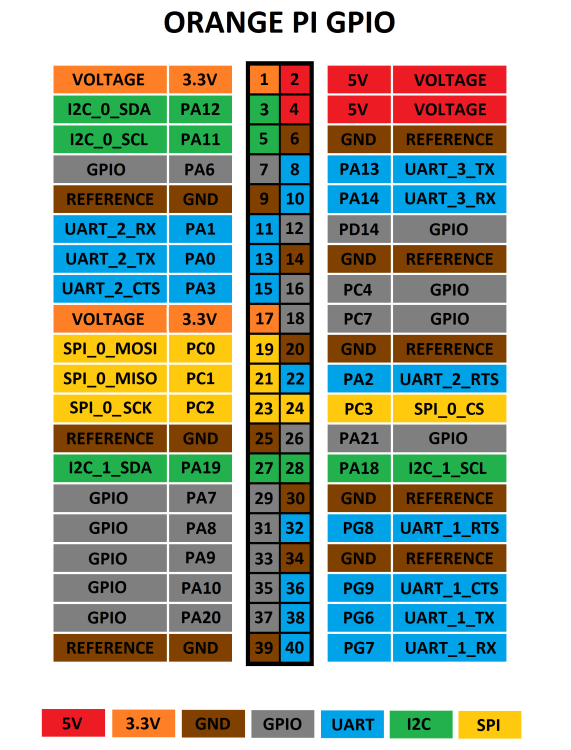
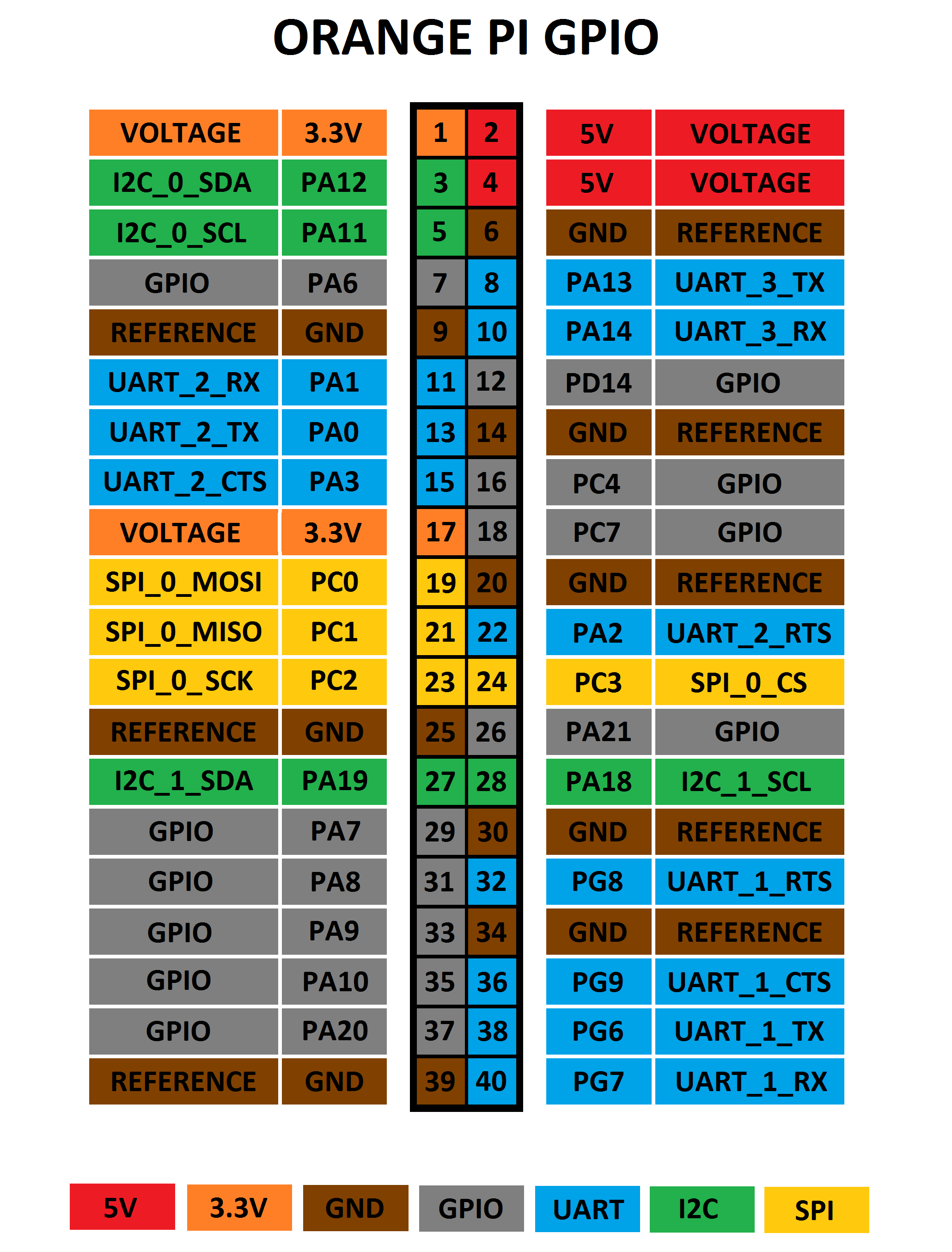
Pinout for the SPI display <==> OrangePi PC : 1 - VCC (1) 3.3v 2 - GND (6) GND 3 - CS (24 PC3) SPI0 CS0 4 - RESET (29 PA7) ILI9341-RST 5 - DC (31 PA8) ILI9341-DC 6 - SDI (MOSI) (19 PC0) SPI0 MOSI 7 - SCLK (23 PC2) SPI0 CLK 8 - LED (33 PA9) Backlight (optional) or 3.3v(17) 9 - SDO (MISO) (21 PC1) SPI0 MISO 10 - T_CLK (23 PC2) SPI0 CLK 11 - T_CS (26 PA21) SPI0 CS1 12 - T_DIN (19 PC0) SPI0 MOSI 13 - T_DO (21 PC1) SPI0 MISO 14 - T_IRQ (35 PA10) TS IRQThe overlay file template may look like this:
/dts-v1/; /plugin/; / { compatible = "allwinner,sun8i-h3"; fragment@0 { target-path = "/aliases"; __overlay__ { spi0 = "/soc/spi@1c68000"; }; }; fragment@1 { target = <&pio>; __overlay__ { spi0_pins: spi0-pins { pins = "PC0", "PC1", "PC2"; function = "spi0"; }; spi0_cs0_pin: spi0-cs0-pin { pins = "PC3"; function = "spi0"; }; }; spi0_cs1_pin: spi0-cs1-pin { pins = "PA21"; function = "spi0"; }; }; ili9341_rst: ili9341-rst { pins = "PA7"; function = "gpio_out"; }; }; ili9341_dc: ili9341-dc { pins = "PA8"; function = "gpio_out"; }; }; /* optional ili9341_led: ili9341-led { pins = "PA9"; function = "gpio_out"; }; }; */ ads7846_pin: ads7846-pin { pins = "PA10"; function = "irq"; }; }; }; fragment@2 { target = <&spi0>; __overlay__ { #address-cells = <1>; #size-cells = <0>; pinctrl-names = "default"; pinctrl-0 = <&spi0_pins>; status = "okay"; ili9341: ili9341@0 { compatible = "ilitek,ili9341"; reg = <0>; pinctrl-names = "default"; pinctrl-0 = <&spi0_cs0_pin>; status = "okay"; spi-max-frequency = <16000000>; rotate = <90>; bgr; fps = <25>; buswidth = <8>; regwidth = <16>; reset-gpios = <&pio &ili9341_rst 0>; dc-gpios = <&pio &ili9341_dc 0>; /*led-gpios = <&pio &ili9341_led 0>; */ }; xpt2046: xpt2046@1 { compatible = "ti,ads7846"; reg = <1>; pinctrl-names = "default"; pinctrl-0 = <&spi0_cs1_pin>; interrupts = <&ads7846_pin>; interrupt-parent = <&pio>; status = "okay"; spi-max-frequency = <1000000>; }; }; }; }; -
9 часов назад, Peter Gregory сказал:
There are problems with the overlay, not sure how to define the pin PA21 so it can be recognized:
drivers/pinctrl/sunxi/pinctrl-sun8i-h3-r.c as r-pio - PL pin's.
drivers/pinctrl/sunxi/pinctrl-sun8i-h3.c as pio - PA, PC, PD, PE, PF, PG pin's.
Invalid:
10 часов назад, Peter Gregory сказал:cs-gpios = <0>, <&r_pio 0 21 0>; /* PA21 */
10 часов назад, Peter Gregory сказал:cs-gpios = <0>, <&r_pio 2 3 0>; /* PC3 */
10 часов назад, Peter Gregory сказал:interrupt-parent = <&r_pio>; /* PA10<-----> TP_IRQ */ pendown-gpio = <&r_pio 0 10 0>;
&r_pio -> &pio
Invalid:
10 часов назад, Peter Gregory сказал:__overlay__ { spi0 = "/soc/spi@5010000"; spi1 = "/soc/spi@5011000";
For your device, you have printed this information:
05.09.2023 в 00:36, Peter Gregory сказал:The DTB used in this image is /boot/dtb/sun8i-h3-orangepi-pc.dtb
The sections you referenced are
pinctrl@1c20800 { spi0-pins { pins = "PC0\0PC1\0PC2\0PC3"; function = "spi0"; phandle = < 0x16 >; }; spi1-pins { pins = "PA15\0PA16\0PA14\0PA13"; function = "spi1"; phandle = < 0x17 >; }; }; spi@1c68000 { compatible = "allwinner,sun8i-h3-spi"; reg = < 0x1c68000 0x1000 >; interrupts = < 0x00 0x41 0x04 >; clocks = < 0x03 0x1e 0x03 0x52 >; clock-names = "ahb\0mod"; dmas = < 0x15 0x17 0x15 0x17 >; dma-names = "rx\0tx"; pinctrl-names = "default"; pinctrl-0 = < 0x16 >; resets = < 0x03 0x0f >; status = "disabled"; #address-cells = < 0x01 >; #size-cells = < 0x00 >; phandle = < 0x5c >; }; spi@1c69000 { compatible = "allwinner,sun8i-h3-spi"; reg = < 0x1c69000 0x1000 >; interrupts = < 0x00 0x42 0x04 >; clocks = < 0x03 0x1f 0x03 0x53 >; clock-names = "ahb\0mod"; dmas = < 0x15 0x18 0x15 0x18 >; dma-names = "rx\0tx"; pinctrl-names = "default"; pinctrl-0 = < 0x17 >; resets = < 0x03 0x10 >; status = "disabled"; #address-cells = < 0x01 >; #size-cells = < 0x00 >; phandle = < 0x5d >; }; __symbols__ { pio = "/soc/pinctrl@1c20800"; spi0_pins = "/soc/pinctrl@1c20800/spi0-pins"; spi1_pins = "/soc/pinctrl@1c20800/spi1-pins"; spi0 = "/soc/spi@1c68000"; spi1 = "/soc/spi@1c69000"; }; -
08.09.2023 в 01:57, Peter Gregory сказал:
which overlays need to be used in armbianEnv.txt?
For this display,
06.09.2023 в 02:19, Peter Gregory сказал:MPI3508 2.8 inch HDMI LCD with ads7846 touch controller (Single SPI needed)
you need to compile and register it yourself. Please publish a successful, correct overlay file here and paste it as a code (button <>).
For this display,
07.09.2023 в 20:16, Peter Gregory сказал:Hosyond 2.8 Inches TFT LCD Touch Screen Shield Display Module 320x240 SPI Serial ILI9341 with Touch Pen Compatible with Arduino R3/Mega2560 Development Board
I looked at Aliexpress. There are many varieties of them. What is the pinout on yours?
You can look through a magnifying glass at the names of the chips to be sure of the correct driver selection for the touch panel.


Custom Image
in Advanced users - Development
Posted
Hello, Frederick.
Will you be able to explain a little. Why exactly this configuration.
Based on the information you provided, I would do the following:
1) Make a standard "Armbian" image for the selected Operating system.
2) Record the image on the SD card.
3) Check the quality of work by booting from the SD.
4)For training, insert a USB-CD adapter with a clean SD card into the USB.
5) Using only the command line and the command (fdisk or parted) to create a partition table
and create the required number of partitions. Write down the sequence of actions in a text file.
This will serve as a template for writing a script.
6) Format the partitions to the selected file system using /usr/sbin/mkfs.FSTYPE
7) To manipulate the LVM partition, use the command '/usr/sbin/lvm'.
Write down the sequence of actions in a mylvm text file in which the first line will contain:
#!/usr/sbin/lvm
Details in 'man lvm'
The lvm command represents its own shell with its own set of commands, so a separate script is needed for it.
You can call it at the required stage in your main BASH script.
Write the main BASH script and check if it works correctly.