

usual user
-
Posts
423 -
Joined
-
Last visited
Content Type
Forums
Store
Crowdfunding
Applications
Events
Raffles
Community Map
Posts posted by usual user
-
-
12 minutes ago, Hero Intelligent said:
Ramdisk image is corrupt or invalid
SCRIPT FAILED: continuing...
broken build
-
7 hours ago, SteeMan said:
the overlays are currently being shared between the h616 and h618.
Overlays are always device-specific, and in most cases, even use-case-specific.
Trying to share between different devices takes a huge amount of maintenance as opposed to a simple copy of a similar overlay. All possible interactions have to be taken into account and expecting NOOB users to understand their dependencies is asking for trouble. And if they do have to be different later, it is even more difficult to sort them apart.
And besides, what advantage does it bring to the user, since all Armbian images only address one specific device at a time? -
7 hours ago, robertoj said:
I didn't integrate it in the whole SBC dtb. I left it as a dtbo and copied it to the user overlays
A perfectly legitimate method, but not always available:
7 hours ago, robertoj said:https://docs.armbian.com/User-Guide_Allwinner_overlays/#armbian-specific-notes
Armbian specific notes
DT overlays are a Work-in-Progress (WIP) feature, present only in certain images.
Please note that different SoCs will have different sets of available overlays.7 hours ago, robertoj said:{check that the GPIO pins are not named}
This is not necessary, an overlay is just an overlay that overlays what already exists. Run the command "fdtoverlay..." three times in a row, keep DTB backups each time and compare them at last.
7 hours ago, robertoj said:I was expecting it that the user overlays appear in the armbian-config utility... but my dtbo didnt show in the system>hardware selection options... is this normal?
This is a question for the one who came up with the overlay application method.
7 hours ago, robertoj said:be careful of conflicts in activating a kernel-provided overlay and a user overlay at the same time
Mainline kernel usually doesn't come with overlays, they are usually added by the Armbian build system. My method should also work in combination.
7 hours ago, robertoj said:Failed to load '/boot/overlay-user/sun50i-h618-orangepi-zero3-con1.dtbo'
Judging by the failure message, the overlay can't be found.
7 hours ago, robertoj said:HOWEVER: the DTSO works when applying it in the DTB, as you suggested. It is only when trying to apply the DTBO with uboot, it fails.
You have thus proven that there is nothing wrong with the base DTB and the DTBO. It is to blame the tool (method) that is used to apply the overlay.
Dynamic application of overlays at boot time is only necessary if the firmare can automatically detect the need to apply an overlay by reading hardware identifiers. This is a method inherited from the Raspberry Pi and has its justification with its expansion modules with hardware identifier.
Using a configuration file (armbianEnv.txt) is just another way of statically selecting overlays and basically the same procedure as my method. I understand that overpaid Armbian developers implement something like this method out of boredom for devices that don't need it and then dynamically apply the statically selected overlays. But I prefer to rely on tools (fdtoverlay) that are more mature. After all, it's used in every kernel build (it's part of the kernel sources) and maintained by the mainline Devicetree developers. And if something didn't work with it, it would immediately stand out and also be repaired. Because kernels are very rarely built 😉 -
6 hours ago, Brendow said:
It kept showing "UUID does not exist" (and I don't know why, so if anybody knows, please tell me).
Chances are, you've destroyed the integrity of the resulting DTB and the kernel can't even access the device with the rootfs.
6 hours ago, Brendow said:really appreciate your efforts @usual user for providing the .dts
That dtso was more ment in @robertoj's direction to showcase gpio-line-names setup for this device.
From the rest of your post, I don't really know what you're talking about. Nevertheless, I have written an overlay from scratch according to your recipe.
For a first test, please disable any overlay application using the Armbian method in armbianEnv.txt and apply the overlay with my method.
With an copy of your base DTB execute this command:fdtoverlay --input sun50i-h6-orangepi-3-lts.dtb --output sun50i-h6-orangepi-3-lts.dtb sun50i-h6-orangepi-3-lts-spi1.dtboNow swap the currently used DTB with this one, reboot and test if it works as expected. After a successful test, you can try out the application with the Armbian method.
-
Out of curiosity and for my own education, I wrote the attached overlay.
If you apply this to the base DTB of the orangepi 3 lts, the GPIO code of @robertoj should be able to run unchanged on this device as well. -
1 hour ago, jumbo125 said:
i want to use a push button on my orange pi.
How to wait for a button press is outlined here.
If you want to be able to write code that is device-agnostic, you'll need to set up generic gpio-line-names.
See here for reference.With that in place e.g.:
gpiomon --num-events=1 con1-08 && my-scriptwill be able to run on any device that has the gpio-line-names set up in the same way.
I.e. will wait at pin 8 of the first extention connector for an event. -
Ok, everything is as expected.
So attached is the overlay source as promised and here is how to use it:
To avoid path information in the commands, I usecd /boot/dtb/allwinner/as the working directory.
To compile the overlay, execute:dtc --in-format dts sun50i-h618-orangepi-zero3-con1.dtso --out sun50i-h618-orangepi-zero3-con1.dtboThis is an one-off action that has only to be repeated when the overlay source changes.
To apply the overlay statically, execute:mv sun50i-h618-orangepi-zero3.dtb sun50i-h618-orangepi-zero3-native.dtb fdtoverlay --input sun50i-h618-orangepi-zero3-native.dtb --output sun50i-h618-orangepi-zero3-con1.dtb sun50i-h618-orangepi-zero3-con1.dtbo ln -s sun50i-h618-orangepi-zero3-con1.dtb sun50i-h618-orangepi-zero3.dtbBy modifying the symlink, you can now easily switch between both or possibly multiple pre-build variants of DTBs, regardless of which overlay application method your system provides or not.
If you don't want pre-built variant support, an in-place application is also possible with:fdtoverlay --input sun50i-h618-orangepi-zero3.dtb --output sun50i-h618-orangepi-zero3.dtb sun50i-h618-orangepi-zero3-con1.dtboThe application of the overlay must always be repeated if the base DTB changes (update). I've attached this feature to my kernel build process so I don't have to worry about it. The kernel install process is also an option to apply local overlays permanently.
Of course, you can also use your OS's overlay application system.
If you want to modify the label names, use my *.dtso as a template and choose a new overlay filename. In this way, both variants can exist at the same time and you can choose as you wish.
Since this overlay only modifies one property value, it can even be applied repeatedly. I.e. with:fdtoverlay --input sun50i-h618-orangepi-zero3.dtb --output sun50i-h618-orangepi-zero3.dtb sun50i-h618-orangepi-zero3-my-labels.dtboyou can simply rewrite the property without any further necessary actions.
I'm sorry that my method doesn't require patches or even rebuilding the entire OS and works in every system from userspace that has the DTC software package installed and the firmware get the DTB provided from the userspace (filesystem) for loading.
Any system administrator should be able to execute the commands (either symlink adjustment or overlay application) from a running system and activate the changes by rebooting. -
11 hours ago, robertoj said:
sun50i-h618-orangepi-zero3.dtb 31.64 kB · 1 download
I've written an overlay that I think is correct. Since I don't have a Orange Pi Zero 3 I need your help to verify my work. Therefore I have applied my overlay staticly to your provided DTB. Please replace your existing DTB with the attached one. Reboot and post the "cat /sys/kernel/debug/gpio" output again.
If everything works as expected, I will post the overlay source and explain how to use it. -
7 hours ago, robertoj said:
What would be needed to have my orangepi zero 3 show this?
As allredy stated, a quite simple DTB overlay. See this thread as an entry point for discussions that have already taken place on this topic.
More on gpio-line-names assignment can also be found in other posts of mine in this forum.
But after the last posts in this thread I have doubts whether I should continue to participate here. IMHO the basic knowledge seems to be lacking, but they think to know exactly what the solution should look like and don't accept any other implementation. Something like this has repeatedly led to inconclusive discussions, which I am no longer prepared to engage in.
If you'd like, I can try to walk you through creating a suitable overlay.
For a first step, I need the output ofcat /sys/kernel/debug/gpiofrom your running system and the DTB that is currently being used for your system. And last but not least, I need an online link to the DTB source of your device or is this already correct.
-
This thread inspired me to tinker with GPIO again. I was curious to see how I would realize the example for myself. Since python is not my strong point, I chose a poor man's solution with "dnf install libgpiod-utils".
I then ran this command:
gpioset --toggle 100ms,100ms,100ms,100ms,100ms,300ms,300ms,100ms,300ms,100ms,300ms,300ms,100ms,100ms,100ms,100ms,100ms,700ms --consumer panic con1-08=activeI'm wondering now what the flashing code could say, but I think a ham radio operator would know for sure what it means 😉
Recreating the python example wasn't really challenging with:gpioset -t1000 -Cblink-example con1-08=1And besides, I find my flashing pattern much more interesting. I would be interested to know how something like this would be implemented with sysfs. Certainly not with a one-liner.
These commands work the same way on all my different devices, i.e. it is used for all pin 8 of the first expansion connector. I find it more pleasant to address the pins with con1-xx than to deal with some device-specific gpio-lines again and again. Generated code is therefore portable and can be used on any device without modification, provided that the device can provide GPIO functionality on the corresponding pins.
The only requirement is that the same gpio-line-name is used for the corresponding GPIO of the extension port. But this can be ensured by a simple DTB overlay. Creating such an overlay is a one-time effort for any device and the first thing I do for a device that I care off. -
-
The gst-play-hevc.mp4-pipeline.pdf is the visualisation of the pipeline composed by:
gst-play-1.0 --use-playbin3 hevc.mp4 -
8 hours ago, jock said:
There is a suggestion on how to modify /etc/mpv/mpv.conf in a proper way
FWIW
I'm keep puzzled about the options you still throw at mpv. In my Wayland environment, I only have "hwdec=auto" and "hwdec-codecs=all" to automatically enforce video hardware decoding (v4l2 via drm KMS) and take into account all possible hardware decoders. This is necessary because otherwise SW decoding is preferred by default.
I also don't understand why you insist on involving the GPU, it doesn't have any business in a video pipeline, as I just demonstrated here. The GPU is only used by the GUI and is therefore secondary. Video playback works perfectly even when no GPU driver is loaded at all. -
On 12/13/2023 at 1:20 PM, Alexander Buzin said:
To be able to play something in your browser it is needed kernel support (which is partly present) and the effort from browser developers to implement such feature (this part is missing).
The output of Code "MOZ_GFX_DEBUG=1 MOZ_LOG="PlatformDecoderModule:5" firefox" tells me a different story, see firefox-nanopc-t4.txt for reference.
If you don't perform any actions with the graphical UI, nvtop confirms very nicely how the GPU and CPU are idle while Firefox plays a video using the VPU:Spoiler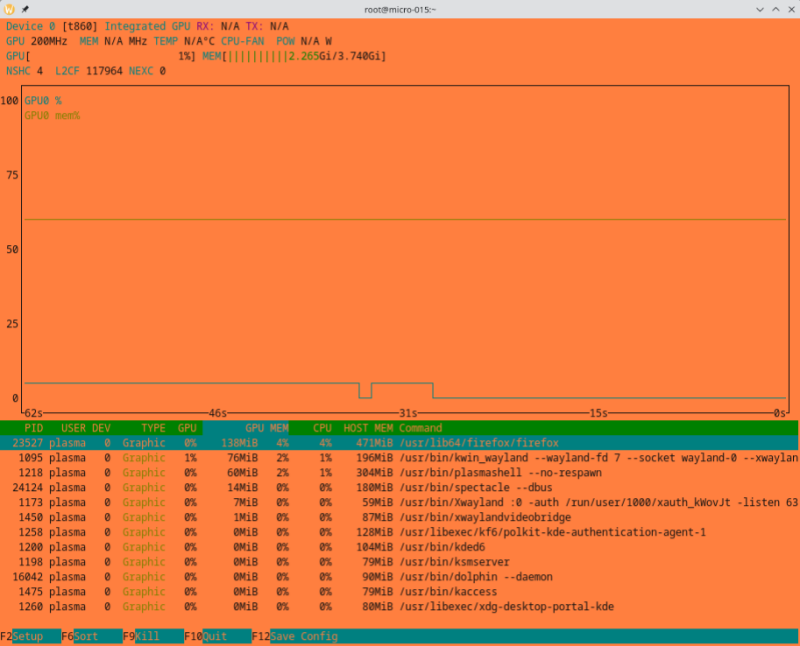
And this is also nice to have:
Spoiler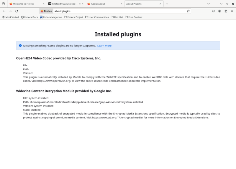
The VPU support of rk356x still lacks rkvdec2 support, but the Hantro decoder is already quite compliant, while the support of gstreamer and FFmpeg decoders is on pair. See fluster-run-odroid-m1-summary.txt for reference. So a lot is already happening.
And all this despite the fact that the distribution of my choice doesn't support any of my devices (not even unofficially). It's all pure mainline, with the exception of the FFmpeg package, which I had to rebuild because the request API support isn't available out-of-the-box there yet.
-
FWIW, I've moved to 6.7.0.rc2 and the mainline USB regression can no longer be observed:
/:  Bus 08.Port 1: Dev 1, Class=root_hub, Driver=ehci-platform/1p, 480M
/:  Bus 07.Port 1: Dev 1, Class=root_hub, Driver=ohci-platform/1p, 12M
    |__ Port 1: Dev 2, If 0, Class=Human Interface Device, Driver=usbhid, 1.5M
    |__ Port 1: Dev 2, If 1, Class=Human Interface Device, Driver=usbhid, 1.5M
/:  Bus 06.Port 1: Dev 1, Class=root_hub, Driver=xhci-hcd/1p, 5000M
    |__ Port 1: Dev 2, If 0, Class=Hub, Driver=hub/4p, 5000M
        |__ Port 4: Dev 3, If 0, Class=Mass Storage, Driver=usb-storage, 5000M
/:  Bus 05.Port 1: Dev 1, Class=root_hub, Driver=xhci-hcd/1p, 480M
    |__ Port 1: Dev 2, If 0, Class=Hub, Driver=hub/4p, 480M
        |__ Port 1: Dev 5, If 0, Class=Vendor Specific Class, Driver=ftdi_sio, 12M
        |__ Port 2: Dev 6, If 0, Class=Vendor Specific Class, Driver=ftdi_sio, 12M
/:  Bus 04.Port 1: Dev 1, Class=root_hub, Driver=ohci-platform/1p, 12M
/:  Bus 03.Port 1: Dev 1, Class=root_hub, Driver=ehci-platform/1p, 480M
/:  Bus 02.Port 1: Dev 1, Class=root_hub, Driver=xhci-hcd/1p, 5000M
    |__ Port 1: Dev 2, If 0, Class=Mass Storage, Driver=uas, 5000M
/:  Bus 01.Port 1: Dev 1, Class=root_hub, Driver=xhci-hcd/1p, 480M
But new toys in town to play with:
Spoilerfluster-run *********************************************************************************************** FriendlyElec NanoPC-T4 CPU 0-3: schedutil 408 MHz - 1416 MHz CPU 4-5: schedutil 408 MHz - 1800 MHz 6.7.0-0.rc2.22.fc37.aarch64+ #1 SMP PREEMPT_DYNAMIC Sat Nov 25 19:54:14 CET 2023 GStreamer-H.264-V4L2SL-Gst1.0 GStreamer-H.265-V4L2SL-Gst1.0 GStreamer-VP8-V4L2SL-Gst1.0 GStreamer-VP9-V4L2SL-Gst1.0 *********************************************************************************************** Running test suite JCT-VC-HEVC_V1 with decoder GStreamer-H.265-V4L2SL-Gst1.0 [TEST SUITE ] (DECODER ) TEST VECTOR ... RESULT ---------------------------------------------------------------------- [JCT-VC-HEVC_V1] (GStreamer-H.265-V4L2SL-Gst1.0) AMP_A_Samsung_7 ... Success ... [JCT-VC-HEVC_V1] (GStreamer-H.265-V4L2SL-Gst1.0) WPP_F_ericsson_MAIN_2 ... Success Ran 116/147 tests successfully in 278.760 secs *********************************************************************************************** Running test suite JVT-FR-EXT with decoder GStreamer-H.264-V4L2SL-Gst1.0 [TEST SUITE] (DECODER ) TEST VECTOR ... RESULT ---------------------------------------------------------------------- [JVT-FR-EXT] (GStreamer-H.264-V4L2SL-Gst1.0) alphaconformanceG ... Success ... [JVT-FR-EXT] (GStreamer-H.264-V4L2SL-Gst1.0) HVLCPFF0_Sony_B ... Success Ran 44/69 tests successfully in 52.795 secs *********************************************************************************************** Running test suite JVT-AVC_V1 with decoder GStreamer-H.264-V4L2SL-Gst1.0 [TEST SUITE] (DECODER ) TEST VECTOR ... RESULT ---------------------------------------------------------------------- [JVT-AVC_V1] (GStreamer-H.264-V4L2SL-Gst1.0) AUD_MW_E ... Success ... [JVT-AVC_V1] (GStreamer-H.264-V4L2SL-Gst1.0) SVA_NL2_E ... Success Ran 129/135 tests successfully in 110.934 secs *********************************************************************************************** Running test suite VP9-TEST-VECTORS with decoder GStreamer-VP9-V4L2SL-Gst1.0 [TEST SUITE ] (DECODER ) TEST VECTOR ... RESULT ---------------------------------------------------------------------- [VP9-TEST-VECTORS] (GStreamer-VP9-V4L2SL-Gst1.0) vp90-2-00-quantizer-00.webm ... Success ... [VP9-TEST-VECTORS] (GStreamer-VP9-V4L2SL-Gst1.0) vp91-2-04-yuv444.webm ... Error Ran 228/305 tests successfully in 329.996 secs *********************************************************************************************** Running test suite VP8-TEST-VECTORS with decoder GStreamer-VP8-V4L2SL-Gst1.0 [TEST SUITE ] (DECODER ) TEST VECTOR ... RESULT ---------------------------------------------------------------------- [VP8-TEST-VECTORS] (GStreamer-VP8-V4L2SL-Gst1.0) vp80-00-comprehensive-001 ... Success ... [VP8-TEST-VECTORS] (GStreamer-VP8-V4L2SL-Gst1.0) vp80-05-sharpness-1443 ... Success Ran 59/61 tests successfully in 14.547 secs -
4 hours ago, j0ta said:
hopefully this u-boot will fix the nvme boot problem I have.
Just out of curiosity, does this firmware build work?
For a test it is sufficient to put it on an otherwise empty microSD card and old the SPI recovery button (RCY) while powering up. No modifications are necessary to the existing system.
-
8 hours ago, Sebastien Motala said:
I change my distribution from debian bookworm to ubuntu jammy.
This is also a valid way to confirm that the problem is a matter of configuration in the boot process.
8 hours ago, Sebastien Motala said:I solve my problem
While this solution does not provide insight into the true cause, it is legitimate. Since Armbian doesn't change the basic structure of the base distribution used, but only improves the device support, the root cause isn't even Armbian's fault.
The developed solution for the operation of the OLED, on the other hand, is exactly within the core competence of Armbian and should be integrated into the build system for general out-of-the-box use.
This is exactly the contribution you can make to give something back for the contributions that other community members have contributed and that you can use for free.
This is the only way the Armbian project can grow, there are already enough users who just take and expect that their special requests will be implemented without their involvement free of charge. In a community driven project, you pay through your own contributions. Contributing nothing is a good prerequisite for being ignored in the future if you ask for support again. -
I still have an idea for an experiment with your problem:
- Blacklist the OLED display driver module so it get not autoloaded at system start
I do it e.g. this way:echo blacklist ssd130x-i2c > /etc/modprobe.d/ssd130x-i2c-blacklist.confBut I don't know if it works the same way in an Armbian system.
- Boot the system without the HDMI monitor connected
- When the boot process is complete, i.e. all automatic graphical console device mappings are complete, modprobe explicit the OLED display driver module
- Report if fbcon is no longer binding to the framebuffer device provided by the OLED driver
If this works, it might serve as a workaround, because I'm not sure if the Armbian configuration framework can handle two separate graphic cards. But I'm happy to be taught better by an Armbian insider.
Oh, by the way, this is not a specific ODROID-M1 problem nor is it special because the display driver uses the i2c interface.
It is a general matter to support several grahic cards at the same time, it doesn't matter which interface they use to communicate. The same would happen, for example, if an additional graphics card is used, which is connected via USB adapter.
This allows you to find solutions from anywhere and then learn how to configure them in Armbian for its automatisms. -
On 10/29/2023 at 11:05 AM, Sebastien Motala said:
Thank you, your DTB file works.
Nice to hear, then I can issue my invoice now 😉
It is now your task to make my contributed knowledge easily available to all Armbian users. Prepare a PR so that my used overlay (which was applied to my provided DTB) will be included in the Armbian build system.
And while you're at it, include this one (also applied to my provided DTB by default) as well. It simplifies GPIO handling and connector pinout identification immensely.
If I am correctly informed, they have even simplified the overlay integration into the build system. All you have to do is make the overlay source available in an appropriate directory. To do this, I have attached the sources of both overlays to this post.
Repairing the pinctrl in the base DTB is not that easy, for this you have to apply the attached patch to the board DTS and rebuild the base DTB. This is necessary so that the correct code artifacts can be integrated into the DTB, this cannot be corrected in a reasonable way with an overlay.
And don't forget, you'll reap a lot of Armbian users who will be grateful for your contribution. Not to mention the fact that your desired functionality will be available out-of-the-box to everyone in the future.On 10/29/2023 at 11:05 AM, Sebastien Motala said:I have another problem the tty1 display on the oled screen.
I'm guessing you only have the OLED display driver loaded in your system and no additional other. This then provides /dev/fb0, which in turn is assigned /dev/tty1 by the system. Usually, the console is also assigned to /dev/tty1 by default.
On 10/29/2023 at 11:05 AM, Sebastien Motala said:Where can i disabled this ?
I don't know the system you're using, but I always configure the console mapping with the kernel command line (/proc/cmdline).
rk3568-odroid-m1-con1.dtsork3568-odroid-m1-lk-oled1.dtsospecify-pinctrl-for-i2c3-adapter-on-ODROID-M1.patch
-
11 hours ago, Sebastien Motala said:
What pins are activated on the GPIO for i2c0 ?
That was a good question. While researching the answer, I noticed that the basic DTB wires the i2c functionality to pads that are inaccessible on this device. After appropriate correction, the i2c functionality is now available on the documented pins of the board.
I plugged in my LK-OLED1 display and it works as expected:# i2cdetect -y 0 0 1 2 3 4 5 6 7 8 9 a b c d e f 00: -- -- -- -- -- -- -- -- 10: -- -- -- -- -- -- -- -- -- -- -- -- -- -- -- -- 20: -- -- -- -- -- -- -- -- -- -- -- -- -- -- -- -- 30: -- -- -- -- -- -- -- -- -- -- -- -- UU -- -- -- 40: -- -- -- -- -- -- -- -- -- -- -- -- -- -- -- -- 50: -- -- -- -- -- -- -- -- -- -- -- -- -- -- -- -- 60: -- -- -- -- -- -- -- -- -- -- -- -- -- -- -- -- 70: -- -- -- -- -- -- -- --I re-uploaded the corrected DTB in the previous post. Please download the DTB again to replace the wrong one.
-
- backup your existing rk3568-odroid-m1.dtb
- replace /boot/dtb/rockchip/rk3568-odroid-m1.dtb with the provided DTB
- disable all currently applied overlays (the provided DTB has everything already wired up)
- reboot and post the output of:# i2cdetect -y 0 -
7 hours ago, Sebastien Motala said:
I add "overlays=rockchip-i2c0" to armbianEnv.txt
I don't know what that overlay wires up but with proper wired DT you should get this:
# i2cdetect -l i2c-0 i2c rk3x-i2c I2C adapter i2c-3 i2c rk3x-i2c I2C adapter i2c-6 i2c DesignWare HDMI I2C adapter -
On 10/24/2023 at 3:41 PM, Sebastien Motala said:
What am i doing wrong ?
The IOs of the expansion connector are multifunction IOs, so the deault configuration does not necessarily correspond to your use case. How did you wire up the corresponding i2c bus in DT?
-
1 hour ago, baryon said:
to get rid of the LibreELEC stage and just have a nice ffmpeg git repo someone can clone to save the awkward steps 1 and 2.
To build ffmpeg with the request API, you usually only need the additional commits that Jernej provides.
433Mhz sender/receiver on Orange Pi Zero 3?
in Allwinner sunxi
Posted
You have provided far too little context, and I do not understand what you are talking about. But if it's just the output of a pattern waveform via a GPIO, you can do it with a one-liner from the command line:
gpioset --toggle 100ms,100ms,100ms,100ms,100ms,300ms,300ms,100ms,300ms,100ms,300ms,300ms,100ms,100ms,100ms,100ms,100ms,700ms --consumer panic con1-08=activeThis is just an example and the emitted pattern doesn't meet your needs, but with adjusted timings it does exactly what you want.
Of course, you can also write your application with program code. Libgpiod provides bindings for C++, python3 and Rust therefor.