
usual user
-
Posts
544 -
Joined
-
Last visited
Content Type
Forums
Store
Crowdfunding
Applications
Events
Raffles
Community Map
Posts posted by usual user
-
-
7 hours ago, ceri said:
What does the shutdown process to that could fix this?
It leaves the device with an intact file system.
The corrupted file system structure has likely been restored by rolling back the journal during the automatic file system check of the unmounted file system at system startup. But the data loss is permanent.
There is a reason why UPS systems exist. -
50 minutes ago, rosenrot00 said:
Thank you that worked.
I don't know your plans for how things are supposed to proceed. But if you plan to continue using my firmware build, I would suggest transferring it to the SPI flash, provided you are not wanted to use any other firmware in there.
- This relieves you from having to pay attention to restoring my firmware build when changing an image.
- You have two firmware versions available to you, between which you can switch with the SPI-MMC boot switch.
- Even without the eMMC module, you can boot an OS from another connected storage device.
- The U-Boot console is also available with an HDMI monitor and a USB keyboard and can be used for analysis in the event of startup problems. Of course, it is also used to select various boot options if autoboot is interrupted. -
21 minutes ago, rosenrot00 said:
Where would I have to place it?
Use:
dd bs=512 seek=1 conv=notrunc,fsync if=odroid-n2/u-boot-meson.bin of=/dev/${entire-device-to-be-used}as outlined in the referenced post to replace the existing firmware on the eMMC.
Firmare is residing outside of partition layout structures so you can only write it by absolute access.
-
26 minutes ago, rosenrot00 said:
Isn’t uboot coming with the armbian image on the emmc?
Certainly, but I don't know if anyone has taken the effort to integrate a current version so far.
27 minutes ago, rosenrot00 said:Could you tell me where I find the most recent uboot?
The mainline U-Boot project always provides the source codes for the latest versions.
You can build it by yourself with the Armbian build framework, or use my build for a quick test. -
6 hours ago, rosenrot00 said:
Would be nice to understand why it doesn't boot.
The log is telling that the firmware can't operate the eMMC:
6 hours ago, rosenrot00 said:Device 0: unknown device Card did not respond to voltage select! : -110
Furthermore, the alternatively attempted BOOTP and PXE boot are also unsuccessful because it seems that a server is found, but the necessary bootflow is not configured correctly.
As you are running a quite dated U-Boot, maybe using a cureent release has better support for the eMMC. -
On 5/24/2025 at 5:03 AM, TinaB said:
I try to get my NanoPC-T4 a second life.
My NanoPC-T4 is still alive:
Spoiler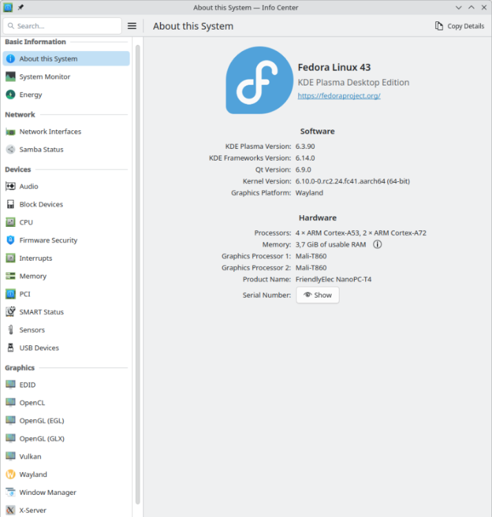
For a quick test, I used my NVME with my latest OS, which usually powers a different SBC:
Spoiler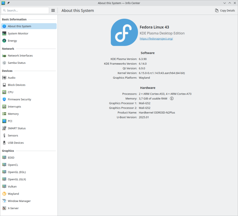
Please do not let it bother you that the NanoPC-T4 uses an outdated kernel to run the OS. This is due to my negligence in building the current kernel without the necessary hacks needed for proper HDMI functionality. Some of the hacks have now been proper implemented in mainline, while others are still in flight. Until this process is completed, I have decided out of laziness to temporarily use an outdated kernel, as I do not miss any functionalities that a current kernel could provide me.
On 5/24/2025 at 5:03 AM, TinaB said:the green blinking light indicates me, that he found no bootable device.
My status LED is not blinking at boot at all. To debug boot problems, blinking LEDs are the worst possible option. Only proper console logs are of value. During OS runtime, it is configured as an HDD LED to indicate access to the microSD, as this is important information for when it is safe to remove it.
On 5/24/2025 at 5:03 AM, TinaB said:The final solution should be that has the bootloader on the eMMC while the rest of the os should be on the SSD
I am still running my firmware from the microSD, again out of laziness to copy it to the eMMC. But any of nessesary support for the NanoPC-T4 is availabe and maybe some boring day or some spezial demand let me revisit to configure it properly. Until then, the bitrottining configuration is sufficient to serve more or less as an always-on terminal server for several USB serial adapters, which provide me with console access to my other SBCs if necessary.
-
8 hours ago, antatarmbian said:
But still I cannot boot the system after removing the sd-card.
EXIT to the U-Boot console and report the output of the following command:
bootflow scan -l nvme8 hours ago, antatarmbian said:I then did armbian-install -> nvme01 Install UEFI system
I don't know what the armbian-install does, but does it make a difference if you dd the same unmodified image to the NVME as you do to the microSD?
-
-
On 1/23/2025 at 8:09 PM, usual user said:
I'm currently at 6.13-rc1 and will stay there at least for another two weeks.
Ok, moved on to 6.14-rc1.
No regressions were observed, only current fixes were applied, and new features were enabled.
It may take some time for some of the fixes to trickle into new stable releases, but the new features are never officially backported.Moved on to 6.15-rc1 (boot-analyze-odroid-m1.pdf).
No regressions were observed, only current fixes were applied, and new features were enabled.
-
Ok, judging by your information, the regression takes place during the transition from U-Boot 2024.04 to 2024.07.
Since mainline U-Boot works perfect for me up to until 2025.01, it must be because of how it's built or what additional patches are applied.
Since it cannot be ruled out that it is due to a incompatible bootflow, it may be interesting to try it with my build.
If this also fails, it is possible to get more information from the HDMI output, even if access to the serial console is not available.
For the test it is perfectly sufficient to start the firmware from a prepared microSD card via RCY button.
The existing setup can stay completely unchanged. -
For me USB works as expected:
Spoiler/: Bus 001.Port 001: Dev 001, Class=root_hub, Driver=xhci-hcd/1p, 480M /: Bus 002.Port 001: Dev 001, Class=root_hub, Driver=xhci-hcd/1p, 5000M |__ Port 001: Dev 002, If 0, Class=Mass Storage, Driver=uas, 5000M /: Bus 003.Port 001: Dev 001, Class=root_hub, Driver=xhci-hcd/1p, 480M /: Bus 004.Port 001: Dev 001, Class=root_hub, Driver=xhci-hcd/1p, 5000M |__ Port 001: Dev 002, If 0, Class=Mass Storage, Driver=uas, 5000M /: Bus 005.Port 001: Dev 001, Class=root_hub, Driver=ehci-platform/1p, 480M |__ Port 001: Dev 002, If 0, Class=Mass Storage, Driver=usb-storage, 480M /: Bus 006.Port 001: Dev 001, Class=root_hub, Driver=ohci-platform/1p, 12M /: Bus 007.Port 001: Dev 001, Class=root_hub, Driver=ehci-platform/1p, 480M |__ Port 001: Dev 002, If 0, Class=Hub, Driver=hub/4p, 480M |__ Port 002: Dev 003, If 0, Class=Human Interface Device, Driver=usbhid, 12M |__ Port 002: Dev 003, If 1, Class=Human Interface Device, Driver=usbhid, 12M |__ Port 002: Dev 003, If 2, Class=Human Interface Device, Driver=usbhid, 12M |__ Port 003: Dev 004, If 0, Class=Vendor Specific Class, Driver=ftdi_sio, 12M |__ Port 004: Dev 005, If 0, Class=Human Interface Device, Driver=usbhid, 1.5M /: Bus 008.Port 001: Dev 001, Class=root_hub, Driver=ohci-platform/1p, 12MI don't have any usbstoragequirks in place because my storage devices have controllers with properly working UAS support.
I'm currently at 6.13-rc1 and will stay there at least for another two weeks. -
2 hours ago, eselarm said:
SBC/embedded Linux does not have GRUB bootmanager by default, otherwise that would be the way to select older kernel.
But I'm grateful that it also works for me with pure U-boot:
SpoilerU-Boot SPL 2025.01 (Jan 16 2025 - 00:00:00 +0000) Trying to boot from SPI ## Checking hash(es) for config config-1 ... OK ## Checking hash(es) for Image atf-1 ... sha256+ OK ## Checking hash(es) for Image u-boot ... sha256+ OK ## Checking hash(es) for Image fdt-1 ... sha256+ OK ## Checking hash(es) for Image atf-2 ... sha256+ OK NOTICE: BL31: v2.12.0(release): NOTICE: BL31: Built : 00:00:00, Nov 27 2024 NOTICE: BL31: Rockchip release version: v1.0 U-Boot 2025.01 (Jan 16 2025 - 00:00:00 +0000) Model: Hardkernel ODROID-M1 SoC: RK3568B2 DRAM: 8 GiB (effective 7.7 GiB) PMIC: RK809 (on=0x80, off=0x08) Core: 324 devices, 37 uclasses, devicetree: separate MMC: mmc@fe2b0000: 1, mmc@fe310000: 0 Loading Environment from nowhere... OK In: serial,usbkbd Out: serial,vidconsole Err: serial,vidconsole Model: Hardkernel ODROID-M1 SoC: RK3568B2 Net: eth0: ethernet@fe2a0000 starting USB... Bus usb@fd000000: Register 2000140 NbrPorts 2 Starting the controller USB XHCI 1.10 Bus usb@fd800000: USB EHCI 1.00 Bus usb@fd840000: USB OHCI 1.0 Bus usb@fd880000: USB EHCI 1.00 Bus usb@fd8c0000: USB OHCI 1.0 scanning bus usb@fd000000 for devices... 1 USB Device(s) found scanning bus usb@fd800000 for devices... 2 USB Device(s) found scanning bus usb@fd840000 for devices... 1 USB Device(s) found scanning bus usb@fd880000 for devices... 5 USB Device(s) found scanning bus usb@fd8c0000 for devices... 1 USB Device(s) found scanning usb for storage devices... 1 Storage Device(s) found scanning bus for devices... SATA link 0 timeout. AHCI 0001.0300 32 slots 1 ports 6 Gbps 0x1 impl SATA mode flags: ncq stag pm led clo only pmp fbss pio slum part ccc apst Card did not respond to voltage select! : -110 Card did not respond to voltage select! : -110 Cannot persist EFI variables without system partition *** U-Boot Boot Menu *** Press UP/DOWN to move, ENTER to select, ESC to quit Standard Boot NVME USB Mass Storage SCSI USB Mass Storage eMMC USB Mass Storage microSD USB Mass Storage Power Off usb 0 mmc 1 nvme 0 Exit Hit any key to stop autoboot: 2 Hit any key to stop autoboot: 1 Scanning for bootflows in all bootdevs Seq Method State Uclass Part Name Filename --- ----------- ------ -------- ---- ------------------------ ---------------- Scanning global bootmeth 'efi_mgr': 0 efi_mgr ready (none) 0 <NULL> ** Booting bootflow '<NULL>' with efi_mgr Loading Boot0000 'usb 0' failed Loading Boot0001 'mmc 1' failed Loading Boot0002 'nvme 0' failed EFI boot manager: Cannot load any image Boot failed (err=-14) Scanning bootdev 'mmc@fe2b0000.bootdev': 1 extlinux ready mmc 1 mmc@fe2b0000.bootdev.part /extlinux/extlinux.conf ** Booting bootflow 'mmc@fe2b0000.bootdev.part_1' with extlinux Boot Options 1: ODROID-M1 40000015-01 2: ODROID-M1 50000006-01 3: NanoPC-T4 40000015-01 4: NanoPC-T4 40000015-01 verbose 5: NanoPC-T4 40000015-01 previous 6: Odroid-N2+ 40000015-01 7: Odroid-N2+ 40000015-01 verbose 8: Odroid-N2+ 40000015-01 previous 9: Odroid-N2+ SPI NOR 40000015-01 10: ODROID-M1 40000015-01 verbose 11: ODROID-M1 40000015-01 previous 12: ODROID-M1 40000015-01 previous verbose Enter choice: 1: ODROID-M1 40000015-01 Retrieving file: /usr/lib/modules/linux/vmlinuz append: loglevel=4 root=PARTUUID=40000015-01 coherent_pool=2M console=ttyS02,1500000 console=tty0 rootwait Retrieving file: /usr/lib/modules/linux/dtb/rockchip/rk3568-odroid-m1.dtb Uncompressing Kernel Image to 0 ## Flattened Device Tree blob at 12000000 Booting using the fdt blob at 0x12000000 Working FDT set to 12000000 Loading Device Tree to 00000000eae82000, end 00000000eae94200 ... OK Working FDT set to eae82000 Starting kernel ...
-
I'm currently at:
# uname -a
Linux micro-015 6.13.0-0.rc1.20241204gitfeffde684ac2.17.fc42.aarch64 #1 SMP PREEMPT_DYNAMIC Sat Dec  7 11:18:10 CET 2024 aarch64 GNU/Linux
And with better wired up in DTB I get:
Spoiler# iperf3 -c odroid-m1 Connecting to host odroid-m1, port 5201 [ 5] local odroid-n2+ port 34366 connected to odroid-m1 port 5201 [ ID] Interval Transfer Bitrate Retr Cwnd [ 5] 0.00-1.00 sec 112 MBytes 941 Mbits/sec 0 461 KBytes [ 5] 1.00-2.00 sec 112 MBytes 941 Mbits/sec 0 510 KBytes [ 5] 2.00-3.00 sec 113 MBytes 945 Mbits/sec 0 560 KBytes [ 5] 3.00-4.00 sec 111 MBytes 934 Mbits/sec 0 585 KBytes [ 5] 4.00-5.00 sec 112 MBytes 943 Mbits/sec 0 684 KBytes [ 5] 5.00-6.00 sec 111 MBytes 928 Mbits/sec 0 718 KBytes [ 5] 6.00-7.00 sec 112 MBytes 944 Mbits/sec 0 718 KBytes [ 5] 7.00-8.00 sec 112 MBytes 935 Mbits/sec 0 792 KBytes [ 5] 8.00-9.00 sec 111 MBytes 933 Mbits/sec 0 830 KBytes [ 5] 9.00-10.02 sec 113 MBytes 928 Mbits/sec 0 830 KBytes - - - - - - - - - - - - - - - - - - - - - - - - - [ ID] Interval Transfer Bitrate Retr [ 5] 0.00-10.02 sec 1.09 GBytes 938 Mbits/sec 0 sender [ 5] 0.00-10.02 sec 1.09 GBytes 937 Mbits/sec receiver iperf Done. # iperf3 -R -c odroid-m1 Connecting to host odroid-m1, port 5201 Reverse mode, remote host odroid-m1 is sending [ 5] local odroid-n2+ port 36326 connected to odroid-m1 port 5201 [ ID] Interval Transfer Bitrate [ 5] 0.00-1.00 sec 87.8 MBytes 735 Mbits/sec [ 5] 1.00-2.00 sec 73.6 MBytes 618 Mbits/sec [ 5] 2.00-3.00 sec 94.2 MBytes 791 Mbits/sec [ 5] 3.00-4.00 sec 90.2 MBytes 757 Mbits/sec [ 5] 4.00-5.00 sec 88.5 MBytes 742 Mbits/sec [ 5] 5.00-6.00 sec 86.0 MBytes 721 Mbits/sec [ 5] 6.00-7.00 sec 87.4 MBytes 733 Mbits/sec [ 5] 7.00-8.00 sec 83.2 MBytes 698 Mbits/sec [ 5] 8.00-9.00 sec 86.0 MBytes 721 Mbits/sec [ 5] 9.00-10.00 sec 79.4 MBytes 666 Mbits/sec - - - - - - - - - - - - - - - - - - - - - - - - - [ ID] Interval Transfer Bitrate Retr [ 5] 0.00-10.00 sec 858 MBytes 720 Mbits/sec 196 sender [ 5] 0.00-10.00 sec 856 MBytes 718 Mbits/sec receiver iperf Done. -
Works for me as for @rmrf.
iperf3 -c ... [ ID] Interval Transfer Bitrate Retr [ 5] 0.00-10.00 sec 1.10 GBytes 942 Mbits/sec 0 sender [ 5] 0.00-10.01 sec 1.09 GBytes 938 Mbits/sec receiver iperf3 -R -c ... [ ID] Interval Transfer Bitrate Retr [ 5] 0.00-10.00 sec 412 MBytes 345 Mbits/sec 485 sender [ 5] 0.00-10.00 sec 410 MBytes 344 Mbits/sec receiver -
On 10/1/2024 at 9:06 PM, Mickynuts said:
I don't need help anymore. As said. I used the uboot present in an earlier version.
Ok, then no further action needs to be taken and your solution can be used by others in the future.
I also don't need any other firmware because my current one works according to my needs.
And for an update, I know how to build and debug it if necessary.In the meantime, I've moved to 2025.01 with HDMI support enabled, so I no longer need the serial console to interact with the firmware.
And boot menus easily allow the free choice of which option should currently be booted. -
6 hours ago, Mickynuts said:
I tried to make a bug report form. But you have to provide an armbianmonitor -u output or something like that. And that doesn't match the fact. The card doesn't even boot.
To get help, you have to provide proper logs. In case of boot problems, these are serial console logs. https://debug.armbian.de
-
On 9/13/2024 at 8:16 PM, Ryzer said:
Please find attached the dts sources
Out of curiosity, I played around a bit with the sources offered.
The overlay compiled from the spi-ili9341-tft.dts source cannot be applied statically to the base DTB. It seems to have something to do with the externally used labels. Unfortunately, my DTC package is currently in FTBFS condition and I can't investigate the cause further at the moment.
I have therefore rewritten the overlay in absolute path notation. I used the given properties for this. I can't make a statement about their correctness, because I don't have a complete circuit diagram or any necessary data sheets at hand.
I'm not particularly familiar with the Allwinner devicetree binding documentation, but as far as I can tell, the properties, when applied to the base DTB statically, are compliant.
If you want, you can run the attached DTB with your device. All components are already statically applied, so you should disable any other dynamically applied overlays.
I would be interested in the "/sys/kernel/debug/gpio" content. -
-
9 hours ago, UmutU123 said:
Same output as in the first post.
This says that the necessary short circuit was not present when the MaskRom code scanned for boot devices.
The short circuit must be ensured before the power supply is switched on, and must be maintained until a few seconds later. The procedure is a three-handed job. One hand fixes the PCB, one hand holds the tweezers, and one hand switches on the power supply.
This can only be reliably ensured with a shelf holder who uses Pogo pinns.IMHO a bad board design for a tinker device. A push button or at least holes for a plug contact to connect a proper switch if necessary would be the better solution. Be grateful to your board designer.
-
19 hours ago, UmutU123 said:
So i got a dc charger but nothing I do gets me into the Maskrom mode.
Since the "upgrade button" is only software readable, and the firmware (U-Boot) that does it is corrupt, only this method remains.
19 hours ago, UmutU123 said:I am not even sure on how to flash the suitable firmware at this point.
In MaskRom_mode I would first delete the corrupt firmware in the eMMC, so that the firmware loading falls back to the microSD card. This allows different firmware variants to be tested without having to use the clunky method to get into the MaskRom_mode.
Then I would prepare a microSD card with supposedly suitable firmware and boot the device with it. The function can be verified looking at the serial console output.
Once a suitable firmware has been identified, I would add an OS image to the microSD card to evaluate the full functionality. It may be possible to speed up the procedure if a complete image with suitable integrated firmware is already available.
Finally, if necessary, the firmware can be placed in the eMMC again. -
18 hours ago, robertoj said:
Why is the row gpio-234 (RESET) not showing up in kernel 5.18.88, but it shows up in kernel 6.6.16?, and then it disappears again with your next experiment with updated libgpiod?
Since I don't even know which system component the supposed GPIO line is connected to, I could only speculate wildly. The appearance is certainly due to the wiring in the DT, but this is also a speculation to which I do not want to comment further, but leave it to qualified people. Alternatively, you could look in the exact DT sources from which the DTBs used at runtime were assembled, but I don't have access to that.
You could also add the line to the output with:gpioset --consumer=reset -c0 234=onbut it certainly won't give the same functionality as in the original case, as it's a completely different use case.
-
4 hours ago, UmutU123 said:
I guess nobody here knows whats wrong?
Your device stalls in early firmware not even the payload (U-Boot) is reached. Which OS is used is anything but important at this point.
Make sure that a suitable firmware is used before you worry about the userspace.
Devices with Rockchip SOCs are unbrickable, you can recover at any time by restoring a suitable firmware. -
On 9/6/2024 at 10:13 AM, robertoj said:
I can see my SBC's DTS with armbian-config > System > DTC ... is this what you meant?
Since there is no public link to the result, I suspect it.
On 9/6/2024 at 10:13 AM, robertoj said:It is almost identical to
Since a single false character in a DTS(O) can already lead to a malfunction in its consuming code, this is completely unsuitable for debugging.
If the DTB's build framework is added as a source of error, be my guest, but please don't expect any help from me in this case.
It's the same as asking an application developer to identify a bug in the compilation toolchain by disassembling their binary application code without having access to the exact sources from which the particular binay was built. -
7 hours ago, robertoj said:
I have a feeling that there's some difference between ili9341.ko (adafruit) and fb_ili9341.ko, in the way they handle GPIOs and SPI pins.
IMHO it is much more likely that the DT description is incorrect, but with the Armbian DT workflow there is not the slightest possibility to verify it automatically with the binding documentation.
But since not even the original DT sources are readily available, you can't even validate them manually.
And once sources are available, they are usually written in disassembler syntax, which does not make them easier to read.
In addition, there is the fact that many attempts are made to merge snippets of DTS from different devices by "copy & paste" in the hope of magically getting a working device. This is just as doomed to failure as the attempt to use arbitrary schematic snippets of various devices to describe a certain PCB for a specific device.
In the DT world it is even more challenging, because the DT layout is even use case dependent and runtime changeable.

Repository for v4l2request hardware video decoding (rockchip, allwinner)
in Reviews, Tutorials, Hardware hacks
Posted
FWIW
rkvdec will be out of staging in 6.17
Be prepared to forward-port existing out-of-tree patches.
cedrus has not seen much movement since a long time
It can therefore be assumed that all necessary out-of-tree modifications from the past must be applied even with the latest kernel version.
Since no mainline developments have taken place, no forward porting should be necessary.