Search the Community
Showing results for 'gpio'.
-
With these instructions, you may get UART5 in ttyS1 https://forum.armbian.com/topic/43718-orange-pi-zero-3-issues-with-gps-on-uart/ https://forum.armbian.com/topic/44034-using-gpio-ports-on-orangepi-zero3/#comment-201030
-
I want to use GPIO Pi16 on the 13 pin expansion header of the board. This pin is claimed by the kernel for the ethernet MAC. According to the SOC Datasheet this pin has the option to provide a 25 MHz clock signal for the ethernet MAC, which is not relevant for this board. Thanks to this Topic https://forum.armbian.com/topic/30274-armbian-build-how-to-modify-dts-file-to-change-gpio-mapping/ and the device tree source files https://github.com/torvalds/linux/blob/master/arch/arm64/boot/dts/allwinner/sun50i-h618-orangepi-zero3.dts, https://github.com/torvalds/linux/blob/master/arch/arm64/boot/dts/allwinner/sun50i-h616-orangepi-zero.dtsi and https://github.com/torvalds/linux/blob/master/arch/arm64/boot/dts/allwinner/sun50i-h616.dtsi i managed to create an overlay named sun50i-h616-fix-emac-pin.dts to release the GPIO pin from the ethernet MAC/kernel. /dts-v1/; /plugin/; / { compatible = "allwinner,sun50i-h616"; fragment@0 { target=<&pio>; __overlay__{ ext_rgmii_pins: rgmii-pins { pins = "PI0", "PI1", "PI2", "PI3", "PI4", "PI5", "PI7", "PI8", "PI9", "PI10", "PI11", "PI12", "PI13", "PI14", "PI15"; function = "emac0"; drive-strength = <40>; }; }; }; fragment@1 { target = <&emac0>; __overlay__ { pinctrl-0 = <&ext_rgmii_pins>; }; }; }; sudo armbian-add-overlay /boot/sun50i-h616-fix-emac-pin.dts Even though I don't really understand how to write device tree overlays, surprisingly I could compile and apply the overlay to the kernel with the command above and it did its job. The GPIO is available now and the ethernet connection still works. Can someone who actually understands this subject review my code and include this change in the right form at the right spot?
-
When I start from scratch with TheGoing repo, linux 6.13.7, I apply my DTS, copy my firmware, and I get this DT (snipped in the area that counts) And the LCD works. And when I start from scratch from the Armbian repo, linux 6.13.11, I apply my DTS, copy my firmware, and get this Device Tree: But the GPIO pins PC7 and PC14 appear unclaimed (as seen in previous post), and the LCD remains white. The linux build configs are practically the same (side in 6.13.11 has the error in SPI configuration) I found that the TheGoing repo has a two less patches applied... the zero 2w seems more relevant IMPORTANT: I just added "-" before "patches.armbian/arm64-dts-sun50i-h618-orangepi-zero2w-Add-missing-nodes.patch" in the: build/patch/kernel/archive/sunxi-6.13/series.conf file, and I finally have the ili9488 LCD working with my ili9488-ads7846 DTS My SBC is the OrangePiZero 3, and I select that specific SBC in the menuconfigs after starting "./compile.sh"
-
Help! My DTS, which used to work with 6.13 and 6.12 from the unofficial repo's from NickA and Going... are not working in the official armbian linux 6.13 This is an issue of not owning the DC and RESET pins, as seen in PC7 and PC14 need to show this: pin 71 (PC7): GPIO 300b000.pinctrl:71 pin 78 (PC14): GPIO 300b000.pinctrl:78 dmesg shows this error: $ dmesg|grep spi [ 1.911366] sun6i-spi 5010000.spi: Error applying setting, reverse things back [ 1.911650] sun6i-spi 5011000.spi: Error applying setting, reverse things back [ 1.917726] sun6i-spi 5010000.spi: Error applying setting, reverse things back [ 1.918005] sun6i-spi 5011000.spi: Error applying setting, reverse things back ... The DTS I used is: I think anyone with Linux 6.13 (armbian official) can try this DTS without an LCD connected to the orange pi zero 3... at this time, I only need that the PC7 and PC14 are owned by the SPI driver.
-
Hi I'm trying to use Armbian with Orange pi 5 Ultra. So far so good The hdmirx is working great! I'm not able to control my gpio pins with PWM in equivalent to orange pi 5 ultra image. I guess that i need to load additional overlays, Am I correct? Please review the armbian logs here: https://paste.next.armbian.com/nekodihico I also noticed that pin numbers were changed if I compare it to the Orange pi OS. Thanks in advance!
-
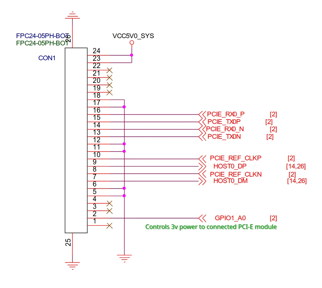
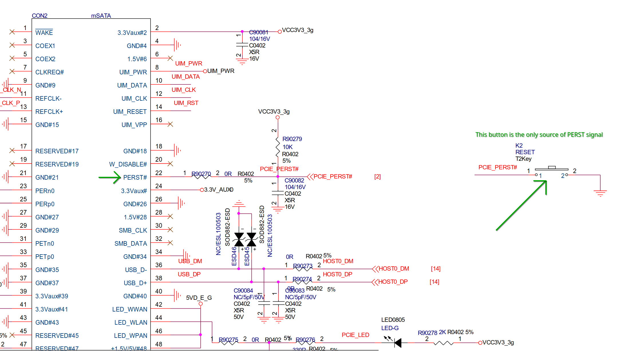
 In our testing, when attempting to use various Wi-Fi mini-PCIe/M.2 adapters from Intel and Realtek, we've encountered problem: oftentimes OS will not see PCIe device with error "PCIe link training gen1 timeout". Some days it happens only in 1/10 boots, other days it can stop working completely. After long debugging we've found that 24-pin FPC cable that connects Orangepi and official connector board (PCIE-SOCKET-OPI4-4B) does not pass PERST signal from Orangepi. Instead, it is high by default and the only way to temporarily set it to low is by pressing physical button on connector board. As far as I understand, PERST signal basically tells the connected device that power and clocks are stable and it can begin link training sequence. Normally, this signal would be controlled from driver code (pcie_rockchip_host.c, rockchip->perst_gpio field) and is assigned to GPIO2_4 pin. During startup sequence it must first be set to low for some time before being set to high after all PCIe clocks are initialized. However, since we don't connect PCI-e directly to rk3399 but through connector cable/board, this code does nothing and instead PERST signal is always high as soon as power is on, leading to link training errors. Simple method to verify the problem: Build custom image (or only kernel) using armbian-build. In kernel configuration, set pcie_rockchip_host module to be compiled as loadable module (<M>) instead of built-in by default. When system fails to see connected PCI-E device at boot, press the reset button on connector board. Execute (you can try this first without pressing button but it will not work): sudo modprobe -vr pcie_rockchip_host && sudo modprobe -v pcie_rockchip_host `lspci` command should now show your device. Thankfully, 24-pin FPC cable does pass GPIO1_A0 signal which we can use as a workaround. By default it is configured as vcc3v3-pcie power regulator, which basically means that it is always on. If we reconfigure it to act as PERST signal, it will become controlled by pcie_rockchip_host Linux driver, which seems to fix the problem. So, the fix is to build custom image/kernel with dts patch below applied (it removes vcc3v3-pcie-regulator nodes and modifies ep-gpios in &pcie0 to use GPIO1_A0): From 8abd7c990fc6f052f335b71df009ec8b88f57a88 Mon Sep 17 00:00:00 2001 From: ArXen42 <arxen42@tutanota.com> Date: Sun, 13 Apr 2025 19:05:52 +0300 Subject: [PATCH] Changed GPIO1_A0 on Orangepi 4 LTS from static power regulator to PCI-E PERST pin --- .../dt/rk3399-orangepi-4-lts.dts | 20 +------------------ 1 file changed, 1 insertion(+), 19 deletions(-) diff --git a/patch/kernel/archive/rockchip64-6.14/dt/rk3399-orangepi-4-lts.dts b/patch/kernel/archive/rockchip64-6.14/dt/rk3399-orangepi-4-lts.dts index c79940457..41eece5a4 100644 --- a/patch/kernel/archive/rockchip64-6.14/dt/rk3399-orangepi-4-lts.dts +++ b/patch/kernel/archive/rockchip64-6.14/dt/rk3399-orangepi-4-lts.dts @@ -128,17 +128,6 @@ }; }; - vcc3v3_pcie: vcc3v3-pcie-regulator { - compatible = "regulator-fixed"; - enable-active-high; - gpio = <&gpio1 RK_PA0 GPIO_ACTIVE_HIGH>; - pinctrl-names = "default"; - pinctrl-0 = <&pcie_drv>; - regulator-always-on; - regulator-boot-on; - regulator-name = "vcc3v3_pcie"; - }; - vcc3v3_sys: vcc3v3-sys { compatible = "regulator-fixed"; regulator-name = "vcc3v3_sys"; @@ -899,7 +888,7 @@ &pcie0 { status = "okay"; - ep-gpios = <&gpio2 4 GPIO_ACTIVE_HIGH>; + ep-gpios = <&gpio1 0 GPIO_ACTIVE_HIGH>; num-lanes = <4>; max-link-speed = <1>; }; @@ -1095,13 +1084,6 @@ drive-strength = <12>; }; - pcie { - pcie_drv: pcie-drv { - rockchip,pins = - <1 RK_PA0 RK_FUNC_GPIO &pcfg_pull_none>; - }; - }; - hdmi { /delete-node/ hdmi-i2c-xfer; }; -- 2.49.0 While this doesn't address schematic problem (we still don't control PERST signal directly), this seems to work nontheless. I think it works because now the following happens: 1) Driver powers off PCIe device (thinking it set PERST signal to low) 2) Driver sets clocks and other PCIe machinery necessary 3) Driver powers on the board, but this time the clock signals are already up and running, so Wi-Fi/SSD/whatever chip initializes propely. At least, that's how I interpret what's happening in driver code below. static int rockchip_pcie_host_init_port(struct rockchip_pcie *rockchip) { struct device *dev = rockchip->dev; int err, i = MAX_LANE_NUM; u32 status; gpiod_set_value_cansleep(rockchip->perst_gpio, 0); // <--- this powers off PCIe device err = rockchip_pcie_init_port(rockchip); if (err) return err; /* Fix the transmitted FTS count desired to exit from L0s. */ status = rockchip_pcie_read(rockchip, PCIE_CORE_CTRL_PLC1); status = (status & ~PCIE_CORE_CTRL_PLC1_FTS_MASK) | (PCIE_CORE_CTRL_PLC1_FTS_CNT << PCIE_CORE_CTRL_PLC1_FTS_SHIFT); rockchip_pcie_write(rockchip, status, PCIE_CORE_CTRL_PLC1); rockchip_pcie_set_power_limit(rockchip); /* Set RC's clock architecture as common clock */ status = rockchip_pcie_read(rockchip, PCIE_RC_CONFIG_LCS); status |= PCI_EXP_LNKSTA_SLC << 16; rockchip_pcie_write(rockchip, status, PCIE_RC_CONFIG_LCS); /* Set RC's RCB to 128 */ status = rockchip_pcie_read(rockchip, PCIE_RC_CONFIG_LCS); status |= PCI_EXP_LNKCTL_RCB; rockchip_pcie_write(rockchip, status, PCIE_RC_CONFIG_LCS); /* Enable Gen1 training */ rockchip_pcie_write(rockchip, PCIE_CLIENT_LINK_TRAIN_ENABLE, PCIE_CLIENT_CONFIG); msleep(PCIE_T_PVPERL_MS); gpiod_set_value_cansleep(rockchip->perst_gpio, 1); // <--- this powers PCIe device back on after all clocks are set up msleep(PCIE_T_RRS_READY_MS); /* 500ms timeout value should be enough for Gen1/2 training */ err = readl_poll_timeout(rockchip->apb_base + PCIE_CLIENT_BASIC_STATUS1, status, PCIE_LINK_UP(status), 20, 500 * USEC_PER_MSEC); if (err) { dev_err(dev, "PCIe link training gen1 timeout!\n"); goto err_power_off_phy; } If you continue to encounter problems with this approach, one other option left is to modify the board itself by rerouting GPIO1_A0 signal to PERST, and leaving 3v power always on, but this will require some soldering work. Changed-GPIO1_A0-on-Orangepi-4-LTS-from-static-power-to-PERST.patch
-
Good morning, I am having some problems with the i2c-1 bus, as it sometimes gets stuck even though I have external pull-up resistors. I need to be able to reset the bus to fix it and check the status of the channels, but I don’t know which Linux GPIO corresponds to the physical pins that the kernel associates with PA18 and PA19. I have tried using wiringPi, but it doesn’t indicate this. Can anyone help me? Thanks!
-
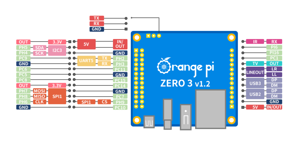
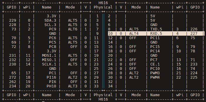
This is going to be a rough tutorial on how to get PWM working on a OrangePi Zero 3 running armbian. Just got this working thanks to (https://forum.armbian.com/profile/9748-going/). I am no expert when it comes to PWM and kernel overlays but this should get you something that works. Enjoy! Install all 4 of the deb's from this link (https://github.com/The-going/PKG_test/tree/master/sunxi64-6.13) after rebooting you should be on 6.13.11. You can check with "uname -r" Edit the file at /boot/armbianEnv.txt and add "pwm1-ph3", "pwm1-pi11", "pwm4-ph1" or "pwm4-pi14" depending on which pwm pin you want to use. Use the included pinout.png for reference. After enabling the overlay I used the gpio command which should be preinstalled on armbian, if not this wiki page tells you how to install. (http://www.orangepi.org/orangepiwiki/index.php/Orange_Pi_Zero_3#How_to_install_wiringOP) "gpio readall" this will print out an ascii diagram of the physical pins on the board as shown in ascii.png. In this case I am using physical pin 10, which corresponds to wPi pin 4 which is what we need for the next commands. (The pin names/number here are going to be different than the ones used previously, it is best to just use the ascii diagram and find what pin you are using instead of basing off of previous pin names) "gpio mode 4 pwm" replace 4 with whatever wPi pin you are using, do this for all following commands. This will set the pin mode in the software to pwm The following information I just learned from doing some googling so it may NOT be 100% correct but it was enough to get it working in my case. "gpio pwmc 4 25" this sets the clock frequency of the PWM pin. The clock frequency is equal to 19200000 divided by the last number specified in the command. So in this case the clock frequency is 768000=19200000/25. "gpio pwmr 4 50" this sets the pwm range and output frequency. range is essentially the resolution of pwm adjustment, higher range means finer control. your final pwm frequency is equal to 19200000/clockvalue/rangevalue. So in this case my pwm frequency is 15360=19200000/25/50. "gpio pwm 4 25" this sets your pwm duty cycle, this is the value you will most likely be changing to control whatever device you have connected to your pwm pin. this number cant be more than your set pwm range, so in this case i have 51 steps because I have any number from and including 0 to 50 to work with. Again I am far from an expert in PWM so I cant guarantee this is all correct but at the very least this shows how to set the needed values with the gpio commands and get PWM working on this board.
-
I keep trying to make my ili9488 SPI LCD with Linux 6.12, from the image in NickA's github... with no success so far Now I have a strong feeling that it is the gpiochip configuration, since I make this test in Linux 6.11 which works with my LCD With Linux 6.11, the device is gpiochip0 With Linux 6.12, the device is gpiochip1 With Linux 6.11, the GPIO lines for reset and command, and the SPI pins, are shown as connected to a function: But with Linux 6.12 (from NickA's github): I had a pending task to check that all the patches for SPI are included in my build... so I check the source code: armbian-nickA-20250306/build/patch/kernel/archive/sunxi-6.12/series.conf And I see that very few patches that are excluded... none of them relate to SPI... I don't know how to make the SPI work in Linux 6.12 as well as it does in Linux 6.12 Am i doing this right? UPDATE: I tried the same DTS, as shown in https://forum.armbian.com/topic/47971-driving-the-ili9488-lcd-40-inch-cheap-chinese-clone/#findComment-208446 with TheGoing build system in his github https://github.com/The-going/armbian-build/tree/main-sunxi-6.12 ... and I still see the SPI pins PH6,7,8 as unclaimed Is anyone able to use the H618 SPI pins in Linux 6.12.x? UPDATE: in this thread, people discuss the gpiochip0 vs gpiochip1 as a sign that the driver is not "occupying" the GPIO, and a DTS change may be needed https://forum.armbian.com/topic/49331-nanopi-neo2-v11-how-to-control-otg-port-power-with-gpio-354/#findComment-210992
-
 I'm using image Armbian_23.8.3_Orangepizero2_bookworm_current_6.1.53 I'm building a DTS overlay for a SPI Touchscreen and every pin I try to use is showing this error: [ 1.441808] sun50i-h616-pinctrl 300b000.pinctrl: pin PC11 already requested by 5011000.spi; cannot claim for 300b000.pinctrl:75 [ 1.441817] sun50i-h616-pinctrl 300b000.pinctrl: pin-75 (300b000.pinctrl:75) status -22 [ 1.441829] sun6i-spi 5011000.spi: cannot register SPI master I'm trying to configure my touchscreen dts to use the SPI1.0 & SPI1.1. However, the pins exposed on the headers are all allocated for device use under 300b000.pinctrl. How do you allocate header pins for another use? I need 5 pins + SPI1 for the touchscreen to work. My dts /dts-v1/; /plugin/; / { compatible = "allwinner,sun8i-h3"; fragment@0 { target = <&pio>; __overlay__ { spi1_cs1: spi1_cs1 { pins = "PC11"; function = "gpio_out"; output-high; }; opiz_display_pins: opiz_display_pins { pins = "PC9", "PC6", "PC5"; function = "gpio_out"; }; ads7846_pins: ads7846_pins { pins = "PH6"; function = "irq"; }; }; }; fragment@1 { target = <&spi1>; __overlay__ { #address-cells = <1>; #size-cells = <0>; status = "okay"; pinctrl-1 = <&spi1_cs1>; pinctrl-names = "default", "default"; cs-gpios= <0>, <&pio 2 11 0>; /* PH9 PC11 */ opizdisplay: opiz-display@0 { reg = <0>; /* Chip Select 0 */ compatible = "ilitek,ili9341"; spi-max-frequency = <16000000>; status = "okay"; pinctrl-names = "default"; pinctrl-0 = <&opiz_display_pins>; rotate = <90>; bgr = <0>; fps = <10>; buswidth = <8>; dc-gpios = <&pio 2 6 0>; /* PC6 */ reset-gpios = <&pio 2 9 1 >; /* PC9 */ led-gpios=<&pio 2 5 0>; /* PC5 */ debug=<0>; }; ads7846: ads7846@1 { reg = <1>; /* Chip Select 1 */ compatible = "ti,ads7846"; spi-max-frequency = <500000>; status = "okay"; pinctrl-names = "default"; pinctrl-0 = <&ads7846_pins>; interrupt-parent = <&pio>; interrupts = <7 6 2>; /* PH6 IRQ_TYPE_EDGE_FALLING */ pendown-gpio = <&pio 7 6 0>; /* PH6 */ /* driver defaults, optional */ ti,x-min = /bits/ 16 <0>; ti,y-min = /bits/ 16 <0>; ti,x-max = /bits/ 16 <0x0FFF>; ti,y-max = /bits/ 16 <0x0FFF>; ti,pressure-min = /bits/ 16 <0>; ti,pressure-max = /bits/ 16 <0xFFFF>; ti,x-plate-ohms = /bits/ 16 <400>; }; }; }; };
 -
Success!! New kernel installed and overlays enabled, pwm works exactly how it should with the gpio command. The pwm chip shows up in /sys/class/pwm instead of /sys/pwm but it works!! Thank you for all the help! If you want more details on what commands i ran to use pwm i can send them.
-
after many day of building and test I have found My TV Box Tanix Tx6 which I use build/patch/kernel/archive/warpme-6.12/0646-arm64-dts-allwinner-h616-add-Tanix-TX6s-axp313-TVbox.patch My TV Box Vontar H618 which I use build/patch/kernel/archive/warpme-6.12/0649-arm64-dts-allwinner-h618-add-vontar-h618-TVbox.patch the Android DTS use different GPIO for bluetooth hex gpio 10 11 13 or dec gpio 16 17 19 (same as transpeed) but warmme patch uses gpio 6 5 4 for my Tanix Tx6s and Vontar H618 I need to edit to Note: &r_pio is gpio connected to CPU not sure if it makes a difference to use &pio
-

How to set correctly GPIO flags in dts files?
firepower replied to TRay's topic in Advanced users - Development
/* Bit 0 express polarity */ #define GPIO_ACTIVE_HIGH 0 #define GPIO_ACTIVE_LOW 1 /* Bit 1 express single-endedness */ #define GPIO_PUSH_PULL 0 #define GPIO_SINGLE_ENDED 2 /* Bit 2 express Open drain or open source */ #define GPIO_LINE_OPEN_SOURCE 0 #define GPIO_LINE_OPEN_DRAIN 4 /* * Open Drain/Collector is the combination of single-ended open drain interface. * Open Source/Emitter is the combination of single-ended open source interface. */ #define GPIO_OPEN_DRAIN (GPIO_SINGLE_ENDED | GPIO_LINE_OPEN_DRAIN) #define GPIO_OPEN_SOURCE (GPIO_SINGLE_ENDED | GPIO_LINE_OPEN_SOURCE) /* Bit 3 express GPIO suspend/resume and reset persistence */ #define GPIO_PERSISTENT 0 #define GPIO_TRANSITORY 8 when combining add the bits #define GPIO_OPEN_DRAIN (GPIO_SINGLE_ENDED | GPIO_LINE_OPEN_DRAIN) is 2+4= 6 gpios = <&pio 0 7 (GPIO_ACTIVE_HIGH|GPIO_OPEN_DRAIN)>; or gpios = <&pio 0 7 4>; -
SOURCE: https://github.com/MathiasStadler/orange-pi-zero-boot-from-spi I spent the whole day trying to boot without a microSD, and I finally got it, using the Orange Pi Zero SPI boot tutorial, with a few adjustments. First of all, you’ll need a microSD card. I used this Armbian version Armbian_24.11.1_Orangepizero2_noble_current_6.6.62_minimal.img.xz Once the system has booted from the microSD: sudo apt update && sudo apt upgrade -y reboot After the system reboots, we need to check if the SPI flash is detected: cat /proc/mtd #It should return something like: dev: size erasesize name mtd0: 00200000 00001000 "spi0.0" #Double-check with: ls -l /dev/mtd* #You should get something like: crw------- 1 root root 90, 0 Apr 10 19:34 /dev/mtd0 crw------- 1 root root 90, 1 Apr 10 19:34 /dev/mtd0ro brw-rw---- 1 root disk 31, 0 Apr 10 19:34 /dev/mtdblock0 /dev/mtd/ total 0 drwxr-xr-x 2 root root 60 Apr 10 19:34 by-name If you see a device at /dev/mtd0 or /dev/mtd/by-name/spi0.0, you can flash U-Boot to the SPI. # Create an empty image sudo dd if=/dev/zero count=2048 bs=1K | tr '\000' '\377' > spi.img # Write U-Boot to the image sudo dd if=/usr/lib/linux-u-boot-current-orangepizero2/u-boot-sunxi-with-spl.bin of=spi.img bs=1k conv=notrunc # Flash the image to SPI sudo flashcp -v spi.img /dev/mtd0 # Or /dev/mtd/by-name/spi0.0 Now it's time to plug in the USB drive (SSD or flash drive): # Install Armbian to the USB stick, pendrive or SSD # Follow the instructions in the menu, default values are usually fine # DON'T REBOOT the device after this step sudo nand-sata-install # Mount the USB stick sudo mount /dev/sda1 /mnt # Copy (overwrite) the /boot directory sudo cp -a /boot /mnt # Now edit /mnt/boot/boot.cmd and set the correct root device: setenv rootdev "/dev/sda1" #Then generate the new boot.scr sudo mkimage -C none -A arm -T script -d /mnt/boot/boot.cmd /mnt/boot/boot.scr #Finally, edit armbianEnv.txt to update the rootdev by UUID: blkid /dev/sda1 #Copy the UUID and update this line rootdev=UUID=your-usb-uuid nano /mnt/boot/armbianEnv.txt Now the moment of truth: sudo shutdown -Fh now Disconnect power and remove the microSD card. Reconnect the power adapter and the system should boot from the USB drive. If there's no sign of life, it's highly recommended to use a UART adapter to debug. Some boards require a jumper between GPIO pins 13 and 14 to boot from SPI — on my board (V1.5), this was not necessary.
-
Did you ever figure out how to get this working? Is the headphone jack on the PoE HAT actually a TRRRS with a mic input connection like on a computer? I know to activate the headphone jack you have to enable a GPIO, maybe there's also one for the mic? I have settings matching the capabilities, but no joy. I always get "set_params:1416: Unable to install hw params:"
-
Does anyone have the i2c working in the orange pi 4a? I tried the debian official image and build my image with the orange pi source code but I can't get it to work, everything works including spi gpio, any help will be appreciated, also I want to build Armbian for the orange pi 4a
-
I rebuild with above corrections and also changed the bluetooth GPIO pins to be same as android. Now I can see bluetooth before it was missing. Tanix-tx6s
-
Hi, Running on Armbian_community 24.8.0-trunk.529 Bookworm with Linux 6.6.43-current-sunxi64 onthe orangepi zero3 And need to use the GPIO pins with python, not an expert here but have tried a few recommandations with no luck. Can anyone suggest method that works with the above OS/build please? Thanks! Rob.
-
So Im not entirely sure if I need to figure out the overlays or something else. On the factory debian image there are two overlays pwm12 and pwm34, i didnt enable them and it seems to work just fine with the gpio command. I should have been more specific, on armbian there are two pwm overlays but they have the prefix of sun50i-h5 and sun50i-h6, i tried enabling them anyway but didnt make a difference and still no pwmchip showing up in /sys/class/pwm. It also is giving me "val pwmWrite 0 <= X <= 1024, Or you can set new range by yourself by pwmSetRange(range)" when i set the pwm value even though I already did set a range and ram the same commands that worked perfectly on the factory image. Im not sure exactly what you mean by core.
-
Great! See https://wiki.radxa.com/Rockpi4/dev/serial-console for a guide on how to connect the serial lines to the board and setting up a terminal program. The wire colours are different, but take a look at the picture on that link: Do not connect the +5V or 3V3 pins GND cable needs to be connected to the 3rd GPIO-pin (GND) on the top/outer side of the connector (the black wire in the picture) RX cable needs to be connected to TX, that's the 4th GPIO-pin, just below the GND wire (it's white in the picture) TX cable needs to be connected to RX, that's the 5th GPIO-pin, just below the RX wire (it's green in the picture) (If you can't connect, then RX and TX needs to be swapped. Don't worry, having these lines swapped won't break anything, it just doesn't allow a connection when wrong.) Then start the terminal program (e.g. putty on Windows or minicom on Linux, both described in that link). When booting the RockPi, you should see the boot messages in the terminal window (otherwise try swapping RX/TX). Keeping the spacebar pressed (in the terminal program, make sure it is selected) should then interrupt the bootloop and you should be able to copy&paste the output. If interrupting still does not work: Putty has the opption to copy the whole content to clipboard: Right-click the title bar and select "Copy All to Clipboard". Then paste it into an editor. Once you have pasted that log into an editor, you can try to clean it up a little bit, it may contain several boot attempts. It would be sufficient to include just one complete boot attempt and the start of the next. But if in doubt, use the complete log. Finally post that log here.
-
Hello everyone, I'm currently working on a bananaPi M2S and trying to set up serial communication through the GPIO port on my device. I am using the provided overlay for UART-A. The overlay seems to work as it registers the serial device, as indicated by the dmesg output: bash [ 0.000277] printk: console [tty1] enabled [ 0.734433] ff803000.serial: ttyAML0 at MMIO 0xff803000 (irq = 14, base_baud = 1500000) is a meson_uart [ 0.734458] printk: console [ttyAML0] enabled [ 0.735241] ffd24000.serial: ttyAML6 at MMIO 0xffd24000 (irq = 15, base_baud = 1500000) is a meson_uart [ 0.735395] serial serial0: tty port ttyAML6 registered [ 2.663304] systemd[1]: Created slice Slice /system/serial-getty. [ 3.140660] systemd[1]: Found device /dev/ttyAML0. However, the device /dev/ttyAML6 does not appear in the /dev folder. Here are the steps I've taken so far: Loaded the UART-A overlay. Verified registration through dmesg logs, which show that ttyAML6 is indeed registered. What I've checked: I ran ls /dev/ttyAML* and /dev/tty* but didn't find ttyAML6. Questions: Is there a known issue with this overlay or an additional step I'm missing to make the device node appear in /dev? Are there specific udev rules I need to add or modify to automatically create the device node? Any help or pointers would be greatly appreciated! Thank you in advance!
-
 TV Box Status Information Template Version 1.0 TV Box Name: MXQ Pro 4k 5G (fake 16GB RAM/128GB ROM) CPU: Allwinner H3 Armbian build file name: Armbian_21.08.1_Orangepipcplus_focal_current_5.10.60.img.xz / Armbian_21.08.1_Orangepipcplus_buster_current_5.10.60.img.xz (both works) DTB file used: <none> Kernel Version: 5.10.60 Distribution Installed: focal and buster Working Ethernet (Yes/No): yes Max Ethernet Speed that works (100/1000): 100M Does wifi work (Yes/No): yes Does bluetooth work (Yes/No): not available Does HDMI audio work (Yes/No): yes Additional Comments (provide any additional information you feel is important): all other functionalities for Orange Pi PC Plus is not available (eg OTG function of USB and no GPIO). You can also run "nand-sata-install" command to install armbian to emmc, works fine, no issues.
 -
 Hello, I bought a card which has an SK6805 LED onboard (https://www.tindie.com/products/hallard/ethtinfo-tic-teleinfo-reader-for-ethernet-esp32/) and I'm wondering if there is a way to control it from my BananaPI IO-8 ? Thanks
 -

Installing Armbian on Vero 4k, does not boot from SD Card
patientgamer replied to patientgamer's topic in Amlogic CPU Boxes
I see some references to bootm, kernel.img and dtb.img in fw_printenv, so tweaking with that may pave the way to booting Armbian properly. However I'm afraid to brick the device in the process. I vaguely remember that it's possible to backup the bootloader, but don't have any experience. Any pointers? Here's the full fw_printenv: EnableSelinux=enforcing Irq_check_en=0 active_slot=normal baudrate=115200 bcb_cmd=get_avb_mode;get_valid_slot; boot_part=boot bootcmd=run osmcfromsd; run osmcfromusb; run storeboot bootdelay=1 cmdline_keys=if keyman init 0x1234; then if keyman read mac ${loadaddr} str; then setenv bootargs ${bootargs} mac=${mac};fi;fi; colorattribute=444,8bit cvbs_drv=0 cvbsmode=576cvbs display_bpp=16 display_color_bg=0 display_color_fg=0xffff display_color_index=16 display_height=1080 display_layer=osd0 display_width=1920 dtb_mem_addr=0x1000000 factory_reset_poweroff_protect=echo wipe_data=${wipe_data}; echo wipe_cache=${wipe_cache};if test ${wipe_data} = failed; then run init_display; run storeargs;if mmcinfo; then run recovery_from_sdcard;fi;if usb start 0; then run recovery_from_udisk;fi;run recovery_from_flash;fi; if test ${wipe_cache} = failed; then run init_display; run storeargs;if mmcinfo; then run recovery_from_sdcard;fi;if usb start 0; then run recovery_from_udisk;fi;run recovery_from_flash;fi; fb_addr=0x7f800000 fb_height=1080 fb_width=1920 fdt_high=0x20000000 firstboot=0 fs_type=rootfstype=ramfs gatewayip=10.18.9.1 hdmimode=1080p60hz hostname=arm_gxbb init_display=get_rebootmode;echo reboot_mode:::: ${reboot_mode};if test ${reboot_mode} = quiescent; then setenv reboot_mode_android quiescent;run storeargs;setenv bootargs ${bootargs} androidboot.quiescent=1;osd open;osd clear;else if test ${reboot_mode} = recovery_quiescent; then setenv reboot_mode_android quiescent;run storeargs;setenv bootargs ${bootargs} androidboot.quiescent=1;osd open;osd clear;else setenv reboot_mode_android normal;run storeargs;osd open;osd clear;imgread pic logo bootup $loadaddr;bmp display $bootup_offset;bmp scale; fi;fi; initargs=init=/init console=ttyS0,115200 no_console_suspend earlycon=aml_uart,0xc81004c0 ramoops.pstore_en=1 ramoops.record_size=0x8000 ramoops.console_size=0x4000 jtag=apao loadaddr=1080000 lock=10001000 netmask=255.255.255.0 osmcfromsd=if mmcinfo; then if fatload mmc 0 ${loadaddr} kernel.img; then run sddtb; setenv bootargs ${bootargs} osmc.bootsource=sd; bootm; fi; fi osmcfromusb=if usb start 0; then if fatload usb 0 ${loadaddr} kernel.img; then run usbdtb; setenv bootargs ${bootargs} osmc.bootsource=usb; bootm; fi; fi otg_device=1 outputmode=1080p60hz page_trace=on preboot=run bcb_cmd; run factory_reset_poweroff_protect;run upgrade_check;run init_display;run storeargs;run upgrade_key;bcb uboot-command;run switch_bootmode; reboot_mode=cold_boot reboot_mode_android=normal recovery_from_flash=get_valid_slot;echo active_slot: ${active_slot};if test ${active_slot} = normal; then setenv bootargs ${bootargs} ${fs_type} aml_dt=${aml_dt} recovery_part={recovery_part} recovery_offset={recovery_offset};if itest ${upgrade_step} == 3; then if ext4load mmc 1:2 ${dtb_mem_addr} /recovery/dtb.img; then echo cache dtb.img loaded; fi;if ext4load mmc 1:2 ${loadaddr} /recovery/recovery.img; then echo cache recovery.img loaded; bootm ${loadaddr}; fi;else fi;if imgread kernel ${recovery_part} ${loadaddr} ${recovery_offset}; then bootm ${loadaddr}; fi;else setenv bootargs ${bootargs} ${fs_type} aml_dt=${aml_dt} recovery_part=${boot_part} recovery_offset=${recovery_offset};if imgread kernel ${boot_part} ${loadaddr}; then bootm ${loadaddr}; fi;fi; recovery_from_sdcard=setenv bootargs ${bootargs} aml_dt=${aml_dt} recovery_part={recovery_part} recovery_offset={recovery_offset};if fatload mmc 0 ${loadaddr} aml_autoscript; then autoscr ${loadaddr}; fi;if fatload mmc 0 ${loadaddr} recovery.img; then if fatload mmc 0 ${dtb_mem_addr} dtb.img; then echo sd dtb.img loaded; fi;setenv bootargs ${bootargs} ${fs_type};bootm ${loadaddr};fi; recovery_from_udisk=setenv bootargs ${bootargs} aml_dt=${aml_dt} recovery_part={recovery_part} recovery_offset={recovery_offset};if fatload usb 0 ${loadaddr} aml_autoscript; then autoscr ${loadaddr}; fi;if fatload usb 0 ${loadaddr} recovery.img; then if fatload usb 0 ${dtb_mem_addr} dtb.img; then echo udisk dtb.img loaded; fi;setenv bootargs ${bootargs} ${fs_type};bootm ${loadaddr};fi; recovery_offset=0 recovery_part=recovery rpmb_state=0 sdc_burning=sdc_burn ${sdcburncfg} sdcburncfg=aml_sdc_burn.ini sddtb=if fatload mmc 0 ${dtb_mem_addr} dtb.img; then echo loaded DTB from SD; else store dtb read $dtb_mem_addr; fi sdr2hdr=0 stderr=serial stdin=serial stdout=serial storeargs=setenv bootargs ${initargs} otg_device=${otg_device} reboot_mode_android=${reboot_mode_android} androidboot.selinux=${EnableSelinux} logo=${display_layer},loaded,${fb_addr},${outputmode} maxcpus=${maxcpus} vout=${outputmode},enable hdmimode=${hdmimode} cvbsmode=${cvbsmode} hdmitx=${cecconfig},${colorattribute} cvbsdrv=${cvbs_drv} irq_check_en=${Irq_check_en} androidboot.firstboot=${firstboot} jtag=${jtag}; setenv bootargs ${bootargs} androidboot.veritymode=enforcing androidboot.hardware=amlogic;setenv bootargs ${bootargs} page_trace=${page_trace};setenv bootargs ${bootargs} androidboot.rpmb_state=${rpmb_state};run cmdline_keys; storeboot=if imgread kernel ${boot_part} ${loadaddr}; then bootm ${loadaddr}; fi;run storeargs; run update; switch_bootmode=get_rebootmode;if test ${reboot_mode} = factory_reset; then setenv reboot_mode_android normal;run storeargs;run recovery_from_flash;else if test ${reboot_mode} = update; then setenv reboot_mode_android normal;run storeargs;run update;else if test ${reboot_mode} = quiescent; then setenv reboot_mode_android quiescent;run storeargs;setenv bootargs ${bootargs} androidboot.quiescent=1;else if test ${reboot_mode} = recovery_quiescent; then setenv reboot_mode_android quiescent;run storeargs;setenv bootargs ${bootargs} androidboot.quiescent=1;run recovery_from_flash;else if test ${reboot_mode} = cold_boot; then setenv reboot_mode_android normal;run storeargs;else if test ${reboot_mode} = fastboot; then setenv reboot_mode_android normal;run storeargs;fastboot;fi;fi;fi;fi;fi;fi; try_auto_burn=update 700 750; update=run usb_burning; run sdc_burning; if mmcinfo; then run recovery_from_sdcard;fi;if usb start 0; then run recovery_from_udisk;fi;run recovery_from_flash; upgrade_check=echo upgrade_step=${upgrade_step}; if itest ${upgrade_step} == 3; then run init_display; run storeargs; run update;else fi; upgrade_key=if gpio input GPIOAO_2; then echo detect upgrade key; sleep 3;if gpio input GPIOAO_2; then run update; fi;fi; upgrade_step=2 usb_burning=update 1000 usbdtb=if fatload usb 0 ${dtb_mem_addr} dtb.img; then echo loaded DTB from usb; else store dtb read $dtb_mem_addr; fi v4kflash=verify wipe_cache=successful wipe_data=successful -
Installing Armbian on Vero 4k, does not boot from SD Card
patientgamer replied to patientgamer's topic in Amlogic CPU Boxes
Apparently I had the baud rate wrong, it should be 115200, which explains the gibberish. Now it prints readable logs: GXL:BL1:9ac50e:a1974b;FEAT:ADFC318C;POC:3;RCY:0;EMMC:0;READ:0;0.0;CHK:0; TE: 136060 BL2 Built : 12:23:15, May 17 2019. gxl g3e531ea - luan.yuan@droid15-sz set vcck to 1120 mv set vddee to 1000 mv Board ID = 2 CPU clk: 1200MHz DQS-corr enabled DDR scramble enabled DDR3 chl: Rank0+1 @ 912MHz bist_test rank: 0 1f 03 3b 32 1a 4b 1c 00 39 34 1a 4e 1b 00 36 2f 17 48 1c 03 35 2f 17 48 623 rank: 1 1d 06 35 30 19 48 18 01 2f 34 1b 4e 19 03 2f 32 19 4b 1c 04 35 30 15 4b 623 - PASS Rank0: 1024MB(auto)-2T-13 Rank1: 1024MB(auto)-2T-13 AddrBus test pass! eMMC boot @ 0 sw8 s emmc switch 3 ok Authentication key not yet programmed get rpmb counter error 0x00000007 emmc switch 0 ok Load fip header from eMMC, src: 0x0000c200, des: 0x01400000, size: 0x00004000, part: 0 New fip structure! Load bl30 from eMMC, src: 0x00010200, des: 0x013c0000, size: 0x0000d600, part: 0 Load bl31 from eMMC, src: 0x00020200, des: 0x05100000, size: 0x0002b400, part: 0 Load bl32 from eMMC, src: 0x0004c200, des: 0x05300000, size: 0x0003f200, part: 0 Load bl33 from eMMC, src: 0x0008c200, des: 0x01000000, size: 0x0007d600, part: 0 NOTICE: BL3-1: v1.0(release):53f813e NOTICE: BL3-1: Built : 15:51:23, May 22 2019 [BL31]: GXL CPU setup! NOTICE: BL3-1: GXL normal boot! NOTICE: BL3-1: BL33 decompress pass mpu_config_enable:system pre init ok dmc sec lock [Image: gxl_v1.1.3389-92241b5 2019-07-02 17:22:35 luan.yuan@droid15-sz] OPS=0x82 21 0b 82 00 1a 00 1b 93 91 16 e7 f0 06 d5 1b 2b [0.678918 Inits done] secure task start! high task start! low task start! INFO: BL3-2: ATOS-V2.4.2-27-g5888df8 #1 Fri Dec 13 14:14:13 2019 +0800 arm INFO: BL3-2: Chip: GXL Rev: B (21:B - 80:2) INFO: BL3-2: crypto engine DMA INFO: BL3-2: secure time TEE INFO: BL3-2: CONFIG_DEVICE_SECURE 0xb200000e U-Boot 2015.01-gce79d13 (Mar 29 2024 - 16:55:50) DRAM: 2 GiB Relocation Offset is: 76e82000 register usb cfg[0][1] = 0000000077f4fb28 [CANVAS]canvas init boot_device_flag : 1 Nand PHY Ver:1.01.001.0006 (c) 2013 Amlogic Inc. init bus_cycle=6, bus_timing=7, system=5.0ns reset failed get_chip_type and ret:fffffffe get_chip_type and ret:fffffffe chip detect failed and ret:fffffffe nandphy_init failed and ret=0xfffffff1 MMC: aml_priv->desc_buf = 0x0000000073e826b0 aml_priv->desc_buf = 0x0000000073e849f0 SDIO Port B: 0, SDIO Port C: 1 co-phase 0x2, tx-dly 0, clock 400000 co-phase 0x2, tx-dly 0, clock 400000 co-phase 0x2, tx-dly 0, clock 400000 emmc/sd response timeout, cmd8, status=0x1ff2800 emmc/sd response timeout, cmd55, status=0x1ff2800 co-phase 0x2, tx-dly 0, clock 400000 co-phase 0x2, tx-dly 0, clock 40000000 [mmc_startup] mmc refix success init_part() 297: PART_TYPE_AML [mmc_init] mmc init success Amlogic multi-dtb tool Multi dtb detected Multi dtb tool version: v2 . Support 2 dtbs. aml_dt soc: gxl platform: p212 variant: 2g dtb 0 soc: gxl plat: p212 vari: 2g dtb 1 soc: gxl plat: p231 vari: 2g Find match dtb: 0 start dts,buffer=0000000073e87240,dt_addr=0000000073e87a40 get_partition_from_dts() 91: ret 0 Amlogic multi-dtb tool Multi dtb detected Multi dtb tool version: v2 . Support 2 dtbs. aml_dt soc: gxl platform: p212 variant: 2g dtb 0 soc: gxl plat: p212 vari: 2g dtb 1 soc: gxl plat: p231 vari: 2g Find match dtb: 0 parts: 11 00: logo 0000000002000000 1 01: recovery 0000000002000000 1 02: rsv 0000000000800000 1 03: tee 0000000000800000 1 04: crypt 0000000002000000 1 05: misc 0000000002000000 1 06: instaboot 0000000020000000 1 07: boot 0000000002000000 1 set has_boot_slot = 0 08: system 0000000040000000 1 09: cache 0000000020000000 2 10: data ffffffffffffffff 4 init_part() 297: PART_TYPE_AML eMMC/TSD partition table have been checked OK! crc32_s:0x1577dad == storage crc_pattern:0x1577dad!!! crc32_s:0xee152b83 == storage crc_pattern:0xee152b83!!! crc32_s:0x79f50f07 == storage crc_pattern:0x79f50f07!!! mmc env offset: 0x27400000 In: serial Out: serial Err: serial reboot_mode=cold_boot NAZARKO: repairing fb addrNAZARKO: repairing osd layerSaving Environment to aml-storage... mmc env offset: 0x27400000 Writing to MMC(1)... done [store]To run cmd[emmc dtb_read 0x1000000 0x40000] _verify_dtb_checksum()-3477: calc 38ccf836, store 38ccf836 _verify_dtb_checksum()-3477: calc 38ccf836, store 38ccf836 dtb_read()-3694: total valid 2 update_old_dtb()-3675: do nothing Amlogic multi-dtb tool Multi dtb detected Multi dtb tool version: v2 . Support 2 dtbs. aml_dt soc: gxl platform: p212 variant: 2g dtb 0 soc: gxl plat: p212 vari: 2g dtb 1 soc: gxl plat: p231 vari: 2g Find match dtb: 0 vpu: clk_level in dts: 7 vpu: vpu_power_on vpu: set clk: 666667000Hz, readback: 666666667Hz(0x300) vpu: vpu_module_init_config vpp: vpp_init cvbs: cpuid:0x21 hpd_state=0 vpp: vpp_matrix_update: 2 cvbs performance type = 6, table = 0 cvbs_config_hdmipll_gxl cvbs_set_vid2_clk Net: dwmac.c9410000amlkey_init() enter! [EFUSE_MSG]keynum is 4 [BL31]: tee size: 0 CONFIG_AVB2: null Start read misc partition datas! info->magic = info->version_major = 1 info->version_minor = 0 info->slots[0].priority = 15 info->slots[0].tries_remaining = 7 info->slots[0].successful_boot = 0 info->slots[1].priority = 14 info->slots[1].tries_remaining = 7 info->slots[1].successful_boot = 0 info->crc32 = -1075449479 active slot = 0 wipe_data=successful wipe_cache=successful upgrade_step=2 reboot_mode:::: cold_boot amlkey_init() enter! amlkey_init() 71: already init! [EFUSE_MSG]keynum is 4 [BL31]: tee size: 0 [OSD]load fb addr from dts:/meson-fb [OSD]fb_addr for logo: 0x7f800000 [OSD]load fb addr from dts:/meson-fb [OSD]fb_addr for logo: 0x7f800000 [OSD]VPP_OFIFO_SIZE:0xfff00fff [CANVAS]addr=0x7f800000 width=3840, height=2160 [Dbg imgread]L535:to read pic (bootup) [Dbg imgread]L542:end read pic sz 8192 [Dbg imgread]L578:bootupOutmode <NULL>,<NULL>, bootup_720, bootup [Dbg imgread]L594:found itemName bootup [Dbg imgread]L621:pic sz 0x3f4b8 [Dbg imgread]L646:end read pic[bootup] [OSD]osd_hw.free_dst_data: 0,719,0,575 [OSD]osd1_update_disp_freescale_enable amlkey_init() enter! amlkey_init() 71: already init! [EFUSE_MSG]keynum is 4 [BL31]: tee size: 0 gpio: pin GPIOAO_2 (gpio 102) value is 1 Command: bcb uboot-command Start read misc partition datas! BCB hasn't any datas,exit! amlkey_init() enter! amlkey_init() 71: already init! [EFUSE_MSG]keynum is 4 [BL31]: tee size: 0 Hit Enter or space or Ctrl+C key to stop autoboot -- : 0 card out co-phase 0x2, tx-dly 0, clock 400000 co-phase 0x2, tx-dly 0, clock 400000 co-phase 0x2, tx-dly 0, clock 400000 emmc/sd response timeout, cmd8, status=0x1ff2800 emmc/sd response timeout, cmd55, status=0x1ff2800 emmc/sd response timeout, cmd1, status=0x1ff2800 (Re)start USB... USB0: USB3.0 XHCI init start Register 2000140 NbrPorts 2 Starting the controller USB XHCI 1.00 scanning bus 0 for devices... 1 USB Device(s) found scanning usb for storage devices... 0 Storage Device(s) found ** Bad device usb 0 ** [Dbg imgread]L360:kernel_size 0x91aa1f, page_size 0x800, totalSz 0x91b800 [Dbg imgread]L361:ramdisk_size 0x2897b5, totalSz 0x289800 [Dbg imgread]L362:dtbSz 0x1c800, Total actualBootImgSz 0xbc1800 [Dbg imgread]L369:Left sz 0xac1800 [Dbg imgread]L376:totalSz=0xbc1800 avb2: 0 ee_gate_off ... avb2: 0 ## Booting Android Image at 0x01080000 ... reloc_addr =73f074b0 copy done No androidboot.dtbo_idx configuredStart read misc partition datas! info->magic = info->version_major = 1 info->version_minor = 0 info->slots[0].priority = 15 info->slots[0].tries_remaining = 7 info->slots[0].successful_boot = 0 info->slots[1].priority = 14 info->slots[1].tries_remaining = 7 info->slots[1].successful_boot = 0 info->crc32 = -1075449479 active slot = 0 active_slot is normal get partition info failed !! amlmmc - AMLMMC sub system Usage: amlmmc read <partition_name> ram_addr addr_byte# cnt_byte amlmmc write <partition_name> ram_addr addr_byte# cnt_byte amlmmc erase <partition_name> addr_byte# cnt_byte amlmmc erase <partition_name>/<device num> amlmmc rescan <device_num> amlmmc part <device_num> - show partition infomation of mmc amlmmc list - lists available devices amlmmc env - display env partition offset amlmmc switch <device_num> <part name> - part name : boot0, boot1, user amlmmc status <device_num> - read sd/emmc device status amlmmc ext_csd <device_num> <byte> - read sd/emmc device EXT_CSD [byte] amlmmc ext_csd <device_num> <byte> <value> - write sd/emmc device EXT_CSD [byte] value amlmmc response <device_num> - read sd/emmc last command response amlmmc controller <device_num> - read sd/emmc controller register amlmmc write_protect <partition_name> <write_protect_type> - set write protect on partition through power_on or temporary amlmmc write_protect <addr_base16> <cnt_base10> <write_protect_type> - set write protect on specified address through power_on or temporary amlmmc send_wp_status <partition_name> send protect status of partition amlmmc send_wp_status <addr_base16> <cnt_base10> send protect status on specified address amlmmc send_wp_type <partition_name> send protect type of partition amlmmc send_wp_type <addr_base16> <cnt_base10> send protect type on specified address amlmmc clear_wp <partition_name> clear write protect of partition amlmmc clear_wp <addr_base16> <cnt_base10> clear write protect on specified addresst amlmmc ds <dev_num> <val> set driver strength amlmmc key - disprotect key partition amlmmc cmd <NULL> failed store - STORE sub-system Usage: store init flag store read name addr off|partition size read 'size' bytes starting at offset 'off' to/from memory address 'addr', skipping bad blocks. store write name addr off|partition size write 'size' bytes starting at offset 'off' to/from memory address 'addr', skipping bad blocks. store rom_write add off size. write uboot to the boot device store erase boot/data: erase the area which is uboot or data store erase partition <partition_name>: erase the area which partition in u-boot store erase dtb store erase key store disprotect key store rom_protect on/off store scrub off|partition size scrub the area from offset and size store dtb iread/read/write addr <size> read/write dtb, size is optional store key read/write addr <size> read/write key, size is optional store ddr_parameter read/write addr <size> read/write ddr parameter, size is optional store mbr addr update mbr/partition table by dtb No dtbo patitions found load dtb from 0x1000000 ...... Amlogic multi-dtb tool Single dtb detected No valid dtbo image found Uncompressing Kernel Image ... OK kernel loaded at 0x01080000, end = 0x02a19a00 libfdt fdt_getprop(): FDT_ERR_NOTFOUND Loading Ramdisk to 73be6000, end 73e6f7b5 ... OK Loading Device Tree to 000000001ffef000, end 000000001ffff976 ... OK signature: fdt_instaboot: no instaboot image Starting kernel ... uboot time: 4083861 us [ 0.000000@0]d Booting Linux on physical CPU 0x0 [ 0.000000@0]d Linux version 4.9.269-62-osmc (root@jenkins) (gcc version 10.2.1 20210110 (Debian 10.2.1-6) ) #1 SMP PREEMPT Thu Oct 17 19:52:38 UTC 2024 [ 0.000000@0]d Based on OSMC upstream commit: b3101f80964a91322a822a1831932c1e3cc9deb8 [ 0.000000@0]d Boot CPU: AArch64 Processor [410fd034] [ 0.000000@0]d earlycon: aml_uart0 at MMIO 0x00000000c81004c0 (options '') [ 0.000000@0]d bootconsole [aml_uart0] enabled [ 0.000000@0]d 07400000 - 07500000, 1024 KB, ramoops@0x07400000 [ 0.000000@0]d 05000000 - 07400000, 36864 KB, linux,secmon [ 0.000000@0]d 7f800000 - 80000000, 8192 KB, linux,meson-fb [ 0.000000@0]d 7d800000 - 7f800000, 32768 KB, linux,di_cma [ 0.000000@0]d 75c00000 - 7d800000, 126976 KB, linux,ion-dev [ 0.000000@0]d 74c00000 - 75c00000, 16384 KB, linux,vdin1_cma [ 0.000000@0]d 74c00000 - 74c00000, 0 KB, linux,ppmgr [ 0.000000@0]d 5b800000 - 73800000, 393216 KB, linux,codec_mm_cma [ 0.000000@0]d 74c00000 - 74c00000, 0 KB, linux,codec_mm_reserved domain-0 init dvfs: 4 efuse_pw_en: 0x3 WARNING! efuse bits is disabled Enable A53 JTAG to AO [ 0.000000@0]d 07400000 - 07500000, 1024 KB, ramoops@0x07400000 [ 0.000000@0]d 05000000 - 07400000, 36864 KB, linux,secmon [ 0.000000@0]d 7f800000 - 80000000, 8192 KB, linux,meson-fb [ 0.000000@0]d 7d800000 - 7f800000, 32768 KB, linux,di_cma [ 0.000000@0]d 75c00000 - 7d800000, 126976 KB, linux,ion-dev [ 0.000000@0]d 74c00000 - 75c00000, 16384 KB, linux,vdin1_cma [ 0.000000@0]d 74c00000 - 74c00000, 0 KB, linux,ppmgr [ 0.000000@0]d 5b800000 - 73800000, 393216 KB, linux,codec_mm_cma [ 0.000000@0]d 74c00000 - 74c00000, 0 KB, linux,codec_mm_reserved [ 0.488554@0]- codec_mm_module_init [ 0.497475@1]- clkmsr c110875c.meson_clk_msr: failed to get msr ring reg0 [ 0.505097@1]- cvbs_out: chrdev devno 264241152 for disp [ 0.777614@1]- dmi: Firmware registration failed. [ 0.783572@1]- vout: error: dummy_venc_clktree_probe: get enci_top_gate error [ 1.257703@3]- mtdoops: mtd device (mtddev=name/number) must be supplied [ 1.292423@3]- cpy 1 is not valid [ 1.296354@3]- cpy 0 is not valid [ 1.305908@3]- c81004c0.serial: clock gate not found [ 1.400652@3]- c11084c0.serial: clock gate not found [ 1.406457@3]- amlogic-new-usb3 d0078080.usb3phy: This phy has no usb port [ 1.421031@3]- ge2d: register address resource is not found [ 1.423804@3]- amvideocap_probe,amvideocap [ 1.425026@3]- use cma buf. [ 1.453406@0]h dil:err:DI_POST_REG_RD:not attach [ 1.473467@0]h dil:err:DI_POST_REG_RD:not attach [ 1.493395@0]h dil:err:DI_POST_REG_RD:not attach [ 1.513467@0]h dil:err:DI_POST_REG_RD:not attach [ 1.517048@3]- vdin0 get fclk_div5 fail [ 1.517149@3]- vdin_drv_probe: vdin0 cannot get msr clk [ 1.522156@3]- vdin1 get fclk_div5 fail [ 1.525331@3]- vdin_drv_probe: vdin1 cannot get msr clk [ 1.534730@3]- Reserved memory: failed to init DMA memory pool at 0x0000000074c00000, size 0 MiB [ 1.543208@3]- video_composer_module_init_1 [ 1.543541@3]- video_composer_probe_3.1:ports[i].name=video_composer.0, i=0 [ 1.550411@3]- video_composer_probe num=1 [ 1.555351@3]- vlock clk not cfg [ 1.582890@3]- cectx c810023c.aocec: not find 'port_num' [ 1.583047@3]- cectx c810023c.aocec: no clock regs [ 1.587438@3]- cectx c810023c.aocec: not find 'arc_port_mask' [ 1.593160@3]- cectx c810023c.aocec: not find 'output' [ 1.601417@0]- cectx c810023c.aocec: wakeup_reason:0x0 [ 1.603351@0]- cectx c810023c.aocec: wakeup_data: 0x0 0x0 [ 1.612446@0]- request_irq error ret=-22 [ 1.612586@0]- dev_pm_set_wake_irq failed: -22 [ 1.619777@0]- page_trace_module_init, create sysfs failed [ 1.629319@0]- spdif-dit spdif_codec: audio_spdif_out_mute can't get pinctrl [ 1.630907@0]- spdif-dit spdif_codec: audio_spdif_in_mute can't get pinctrl [ 1.637905@0]- spdif-dit spdif_codec: audio_spdif_in can't get pinctrl [ 1.860977@0]- aml_meson_snd_card aml_sound_meson: ASoC: no source widget found for LOUTL [ 1.863652@0]- aml_meson_snd_card aml_sound_meson: ASoC: Failed to add route LOUTL -> direct -> Ext Spk [ 1.873002@0]- aml_meson_snd_card aml_sound_meson: ASoC: no source widget found for LOUTR [ 1.881221@0]- aml_meson_snd_card aml_sound_meson: ASoC: Failed to add route LOUTR -> direct -> Ext Spk [ 1.892112@0]- meson-gxl-pinctrl pinctrl@4b0: pin GPIOH_6 already requested by jtag; cannot claim for aml_sound_meson [ 1.901120@0]- meson-gxl-pinctrl pinctrl@4b0: pin-22 (aml_sound_meson) status -22 [ 1.908339@0]- meson-gxl-pinctrl pinctrl@4b0: could not request pin 22 (GPIOH_6) from group i2s_am_clk on device pinctrl-meson [ 1.919854@0]- aml_meson_snd_card aml_sound_meson: Error applying setting, reverse things back [ 1.944521@3]- hub 2-0:1.0: config failed, hub doesn't have any ports! (err -19) [ 1.946477@3]- usb usb2: Unsupported the hub [ 2.072708@3]- pm-meson aml_pm: Can't get switch_clk81 [ 2.151340@3]- hdmitx: s-val 2199 h_total 2200[ 2.361831@0]- vfm_map_store:rm default [ 2.361831@0]- [ 2.362033@0]- vfm_map_store:add default decoder ppmgr deinterlace amlvideo amvideo [ 2.362033@0]- ERROR SECURITY_KEY_READ 1 the package has 110 fws totally. The TA version (v0.2) is lower than the pkg version (v0.3). The TA version is too low that may affect the work please update asap. The TA ver is v0.2 The fw ver is v0.3 the fw with 512 KB will be loaded. OSMC: Open Source Media Center osmc ttyS0 osmc login: