Search the Community
Showing results for tags 'tutorial'.
-
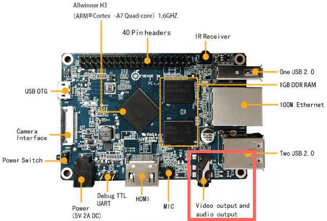
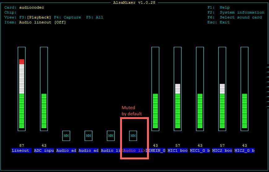
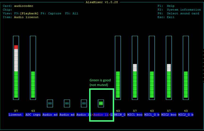
 Hi All, After I accomplished my IR Red Key Rick Rolling experiment the other day with much success, and from general end-luser use with Armbian, there were two things which irritated me, which are namely due to the default ALSA configuration that comes with stock Debian and that Armbian inherits. These were: Update: 11 September 2017. This guide will not work for newer Armbiam (Debian) installations which comes with Pulseaudio by default. If you really want what this tutorial provides, you will need to uninstall pulseaudio first: sudo apt-get remove pulseaudio 1) You can't have simultaneous applications using an Audio device. So, how about if I want to stream Internet Radio with 'Radio Tray' but also get system alert sounds, or anything else? Out of luck, you'll get (for example): [ao/alsa] Playback open error: Device or resource busy 2) I want to actually have audio going out of the 3.5mm jack (don't really care about video out), better still if it's the same/simultaneous to what is going out via. HDMI. That means if I have a HDMI TV connected then I can get the sound from the TV, if I don't, then I can just use the 3.5mm jack (i.e. If I'm using my Pi to play Rick Astley headless/without a TV). No need to keep editing /etc/asound.conf every time. Solution? Step 1) Fix the mute on the analog Line-Out in alsamixer (for a start) There's a lot of noise out there about people not being able to get any sound our of the analog Line-Out jack even when having changed /etc/asound.conf. The reason for this is likely due to a mute by default on the analog audio line-out (i.e. the 3.5mm headphone jack) in alsa that you would unlikely to be aware of. I only found this out thanks to a comment here, otherwise I would have thrown by Pi PC out the window today. So to fix, you need to type in the console: sudo alsamixer Then F6 select the 'audiocodec', then tap the right arrow key to select the 'Audio lineout [Off]' item. Press 'm' and you'll get the green 'OO', which means it's now active. Exit alsamixer, and when you're back at the console type: sudo alsactl store 0 ... to store you mixer settings. For your information, the mixer settings are stored to the file: /var/lib/alsa/asound.state ... and if you do a diff of this file after having made the changes in alsamixer, this is what is changed in the alsa asound.state file: control.9 { control.9 { iface MIXER iface MIXER name 'Audio lineout' name 'Audio lineout' value false | value true comment { comment { access 'read write' access 'read write' type BOOLEAN type BOOLEAN count 1 count 1 } } } } Step 2) Change the /etc/asound.conf file As you might or might not be aware, the default /etc/asound.conf file looks something like this: pcm.!default { type hw card 1 } ctl.!default { type hw card 1 } All it is configured to do is give applications direct access to the hardware audio device, and pump the sound either out to the analogue line-out ('card 0') or via HDMI ('card 1'). Pretty basic, but does the job. However, what I wanted was two things: Software mixing before the resulting PCM/Sound is sent to the hardware audio device - This enables me to listen to Internet Radio and Youtube at the same time... Simultaneous Output to both HDMI and analog line-out. If you want only (1) above, and only via HDMI, then the /etc/asound.conf file is this: pcm.!default { type plug slave.pcm "dmixer" } pcm.dmixer { type dmix ipc_key 1024 slave { pcm "hw:1,0" # "hw:1,0" means HDMI change to "hw:0,0" for analog lineout jack output period_time 0 period_size 1024 buffer_size 4096 rate 44100 } bindings { 0 0 1 1 } } ctl.dmixer { type hw card 0 } ctl.!default { type hw card 0 } If you want (1) and (2) (which of course you do), then the /etc/asound.conf file is this: # Thanks to: http://alsa.opensrc.org/Asoundrc#Dupe_output_to_multiple_cards # https://sourceforge.net/p/alsa/mailman/message/33476395/ # Check that a MUTE doesn't exist on the Audio Line Out for Orange PI PC # or you'll get no sound other than via HDMI pcm.!default { type plug slave.pcm "duplicate" } ctl.!default { type hw card 0 } # Create the Software Mixer for HDMI and then link to hardware pcm.hdmi-dmixer { type dmix ipc_key 1024 slave { #pcm "hw:0,0" # pcm "duplicate" pcm "hdmi-hw" # pcm "analog-hw" period_time 0 period_size 1024 buffer_size 4096 rate 44100 } bindings { 0 0 1 1 } } ctl.hdmi-dmixer { type hw card 0 } # Create the Software Mixer for Analogue Out and then link to hardware pcm.analog-dmixer { type dmix ipc_key 2048 slave { #pcm "hw:0,0" # pcm "duplicate" # pcm "hdmi-hw" pcm "analog-hw" period_time 0 period_size 1024 buffer_size 4096 rate 44100 } bindings { 0 0 1 1 } } ctl.analog-dmixer { type hw card 0 } # Route the audio requests to both hardware devices via the mixer. # For some reason we can't have one mixer and then route to two hardware # devices (would be more efficient). pcm.duplicate { type route slave.pcm { type multi slaves { a { pcm "analog-dmixer" channels 2 } h { pcm "hdmi-dmixer" channels 2 } } bindings [ { slave a channel 0 } { slave a channel 1 } { slave h channel 0 } { slave h channel 1 } ] } ttable [ [ 1 0 1 0 ] [ 0 1 0 1 ] ] } ctl.duplicate { type hw; card 0; } # Physical Output Device Mappings - Analogue and HDMI for Orange PI PC pcm.analog-hw { type hw card 0 } pcm.hdmi-hw { type hw card 1 } There you have it. The only downside is that CPU usage for playing music will increase a bit as ALSA will essentially route inputs from applications to two Software Mixers, which are connected to the HDMI and Analog Line-Out hardware devices separately. For some reason you can't have a single Software Mixer route to two hardware devices (or I couldn't get it to work), but whatever. We're talking 20% CPU usage vs. 10% on one core, to play music.

-
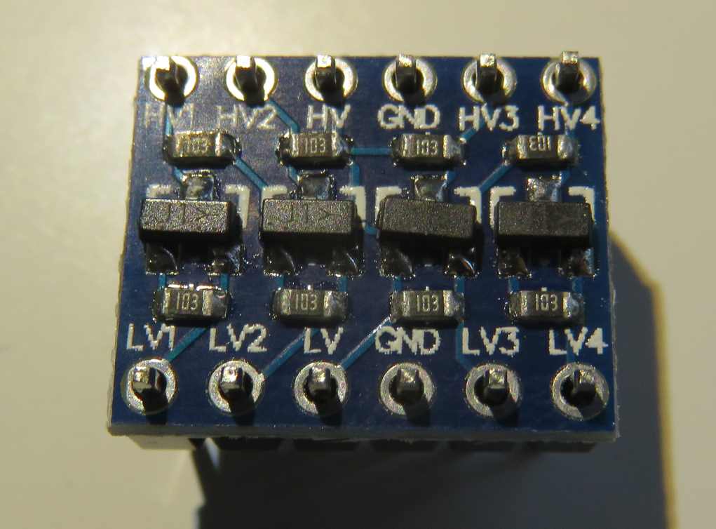
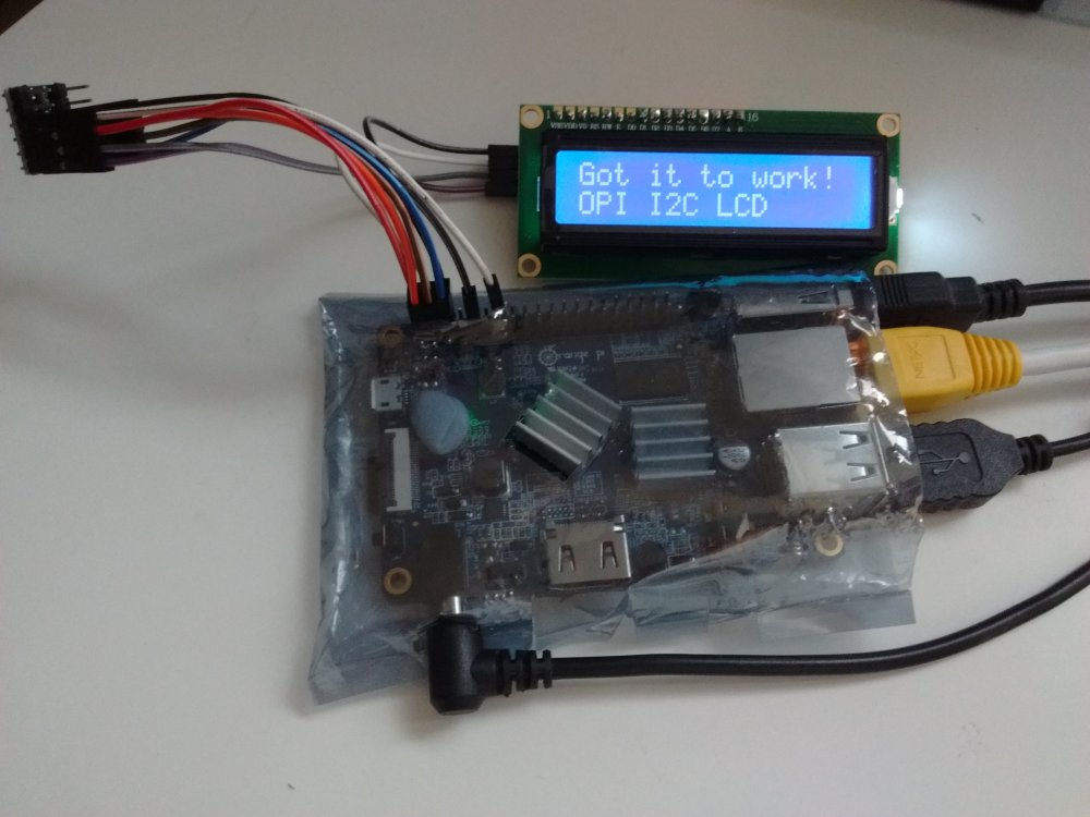
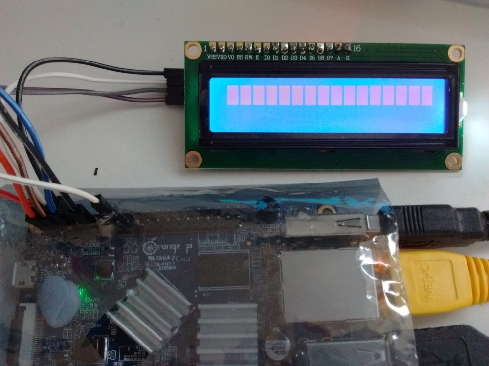
Hi All, I recently bought a cheap 16 character, 2 row LCD display from aliexpress.com for use with my Orange Pi PC. I got it to work without too much pain, but I thought I would document it here for the benefit of others. Some good instructions are already available on the internet, but there are some tweaks required for the Orange PI. Armbian I believe already has the I2C module compiled into the kernel directly. So no Linux Kernal insmod work required, unlike what many Raspberry PI guides seem to imply. Step 1) Buy the things you will need. 1. You obviously need a 1602 LCD module which also comes with the the I2C converter. You can buy a 1602 LCD and wire it directly to the 16 GPIO pins required if you want, but that isn't the point of this guide. 2. You will need a level shifter. The LCD display works on +5volts. The OrangePI/H3 GPIO pins are 3.3 volts. I have seen guides stating that you don't need a level shifter, but I'm sure you're slowly frying some transistors in your OrangePI over time. 3. You will need a bunch of jumper cables etc. Like these, female to female only required really. Step 2) Wire things up accordingly. Thanks to this fantastic guide, the instructions on wiring the Orange PI to the Level Shifter LV ('low voltage') pins, and then the Level Shifter HV ('high voltage') pins to the 1602 I2C module is pretty clear: http://www.raspberrypi-spy.co.uk/2015/05/using-an-i2c-enabled-lcd-screen-with-the-raspberry-pi/ Level Shifter OrangePI 1602 I2C Backpack LV 3.3V (pin 1) – LV1 SDA (pin 3) – LV2 SCL (pin 5) – GND GND (pin 6) GND HV 5V (pin 2) VCC HV1 SDA HV2 SCL Note, you connect the 1602 I2C module/backpack directly to the 5Volt Pin on the PI (Pin 2 or 4) and Ground (Pin 6) respectively. Note: For some strange reason the level shifter works if you don't connect the ground pins to either side of it (i.e. Use the LV, LV1, LV2, HV, HV1 and HV2 pins only). No idea why - electrical engineering degree required I think. If all works well, you should see the LCD module light-up with the top row being a bunch of white bars (you might need to check the contrast setting of the module as well). White bars = uninitialised LCD screen. Step 3) Install the required packages int Armbian Reference: https://www.abelectronics.co.uk/kb/article/1061/i2c--smbus-and-armbian-linux sudo apt-get install -y python-smbus i2c-tools Step 4) Check to see what the address of the LCD Screen is: Reference: http://www.raspberrypi-spy.co.uk/2014/11/enabling-the-i2c-interface-on-the-raspberry-pi/ user@orangepipc:~/Downloads/i2c$ sudo i2cdetect -y 0 [sudo] password for userpi: 0 1 2 3 4 5 6 7 8 9 a b c d e f 00: -- -- -- -- -- -- -- -- -- -- -- -- -- 10: -- -- -- -- -- -- -- -- -- -- -- -- -- -- -- -- 20: -- -- -- -- -- -- -- -- -- -- -- -- -- -- -- -- 30: -- -- -- -- -- -- -- -- -- -- -- -- -- -- -- 3f 40: -- -- -- -- -- -- -- -- UU -- -- -- -- -- -- -- 50: -- -- -- -- -- -- -- -- -- -- -- -- -- -- -- -- 60: -- -- -- -- -- -- -- -- -- -- -- -- -- -- -- -- 70: -- -- -- -- -- -- -- -- user@orangepipc:~/Downloads/i2c$ sudo i2cdetect -y 1 0 1 2 3 4 5 6 7 8 9 a b c d e f 00: -- -- -- -- -- -- -- -- -- -- -- -- -- 10: -- -- -- -- -- -- -- -- -- -- -- -- -- -- -- -- 20: -- -- -- -- -- -- -- -- -- -- -- -- -- -- -- -- 30: -- -- -- -- -- -- -- -- -- -- -- -- -- -- -- -- 40: -- -- -- -- -- -- -- -- -- -- -- -- -- -- -- -- 50: -- -- -- -- -- -- -- -- -- -- -- -- -- -- -- -- 60: -- -- -- -- -- -- -- -- -- -- -- -- -- -- -- -- 70: -- -- -- -- -- -- -- -- Looks like it's 0x3f as the address on I2C bus 0 (which is apparently right according to the aliexpress buyer feedback comments) Step 5) Download Example Script Reference: http://www.raspberrypi-spy.co.uk/2015/05/using-an-i2c-enabled-lcd-screen-with-the-raspberry-pi/ The example script will allow you to send text to the screen via I2C. It is very similar to my scripts for the normal 16×2 screen. To download the script directly to your Pi you can use : wget https://bitbucket.org/MattHawkinsUK/rpispy-misc/raw/master/python/lcd_i2c.py Step 6) Adjust the Sample Script I need to adjust the script to reference a 1602 LCD device with address 0x3f, on Orange Pi PC I2C Bus, 0. The script as it is references a device of 0x27 on Bus 1 - it won't work. You might have a LCD device of address 0x27 (you'll know from the previous step), but it seems many of the cheap LCD modules from aliexpress are 0x3f for some reason. Adjusted script below: #!/usr/bin/python #-------------------------------------- # ___ ___ _ ____ # / _ \/ _ \(_) __/__ __ __ # / , _/ ___/ /\ \/ _ \/ // / # /_/|_/_/ /_/___/ .__/\_, / # /_/ /___/ # # lcd_i2c.py # LCD test script using I2C backpack. # Supports 16x2 and 20x4 screens. # # Author : Matt Hawkins # Date : 20/09/2015 # # http://www.raspberrypi-spy.co.uk/ # # Copyright 2015 Matt Hawkins # # This program is free software: you can redistribute it and/or modify # it under the terms of the GNU General Public License as published by # the Free Software Foundation, either version 3 of the License, or # (at your option) any later version. # # This program is distributed in the hope that it will be useful, # but WITHOUT ANY WARRANTY; without even the implied warranty of # MERCHANTABILITY or FITNESS FOR A PARTICULAR PURPOSE. See the # GNU General Public License for more details. # # You should have received a copy of the GNU General Public License # along with this program. If not, see <http://www.gnu.org/licenses/>. # #-------------------------------------- import smbus import time # Define some device parameters I2C_ADDR = 0x3f # I2C device address LCD_WIDTH = 16 # Maximum characters per line # Define some device constants LCD_CHR = 1 # Mode - Sending data LCD_CMD = 0 # Mode - Sending command LCD_LINE_1 = 0x80 # LCD RAM address for the 1st line LCD_LINE_2 = 0xC0 # LCD RAM address for the 2nd line LCD_LINE_3 = 0x94 # LCD RAM address for the 3rd line LCD_LINE_4 = 0xD4 # LCD RAM address for the 4th line LCD_BACKLIGHT = 0x08 # On #LCD_BACKLIGHT = 0x00 # Off ENABLE = 0b00000100 # Enable bit # Timing constants E_PULSE = 0.0005 E_DELAY = 0.0005 #Open I2C interface bus = smbus.SMBus(0) # Rev 1 Pi uses 0 (and Orange PI PC, for pins 3 and 5) #bus = smbus.SMBus(1) # Rev 2 Pi uses 1 def lcd_init(): # Initialise display lcd_byte(0x33,LCD_CMD) # 110011 Initialise lcd_byte(0x32,LCD_CMD) # 110010 Initialise lcd_byte(0x06,LCD_CMD) # 000110 Cursor move direction lcd_byte(0x0C,LCD_CMD) # 001100 Display On,Cursor Off, Blink Off lcd_byte(0x28,LCD_CMD) # 101000 Data length, number of lines, font size lcd_byte(0x01,LCD_CMD) # 000001 Clear display time.sleep(E_DELAY) def lcd_byte(bits, mode): # Send byte to data pins # bits = the data # mode = 1 for data # 0 for command bits_high = mode | (bits & 0xF0) | LCD_BACKLIGHT bits_low = mode | ((bits<<4) & 0xF0) | LCD_BACKLIGHT # High bits bus.write_byte(I2C_ADDR, bits_high) lcd_toggle_enable(bits_high) # Low bits bus.write_byte(I2C_ADDR, bits_low) lcd_toggle_enable(bits_low) def lcd_toggle_enable(bits): # Toggle enable time.sleep(E_DELAY) bus.write_byte(I2C_ADDR, (bits | ENABLE)) time.sleep(E_PULSE) bus.write_byte(I2C_ADDR,(bits & ~ENABLE)) time.sleep(E_DELAY) def lcd_string(message,line): # Send string to display message = message.ljust(LCD_WIDTH," ") lcd_byte(line, LCD_CMD) for i in range(LCD_WIDTH): lcd_byte(ord(message[i]),LCD_CHR) def main(): # Main program block # Initialise display lcd_init() while True: # Send some test lcd_string("RPiSpy <",LCD_LINE_1) lcd_string("I2C LCD <",LCD_LINE_2) time.sleep(3) # Send some more text lcd_string("> RPiSpy",LCD_LINE_1) lcd_string("> I2C LCD",LCD_LINE_2) time.sleep(3) if __name__ == '__main__': try: main() except KeyboardInterrupt: pass finally: lcd_byte(0x01, LCD_CMD) Step 7) ADD YOUR USER ACCOUNT TO 'i2c' GROUP This is a really useful thing to do, otherwise you'll need to run the python script as ROOT (via. sudo etc.) every time. No good if you want to write a python script that runs using your normal user account and sends messages over I2C to the LCD. Reference: https://www.abelectronics.co.uk/kb/article/1061/i2c--smbus-and-armbian-linux sudo adduser <YOUR_USER_ID> i2c eg: sudo adduser johnsmith i2c Step 8) Run your script! python lcd_i2c.py Amazing! Please note: You can probably use a more advanced library to output data to the LCD, but for now, it probably isn't required: https://gist.github.com/DenisFromHR (you will need to adjust the code in 'RPi_I2C_driver.py' to refer to port=0, not port=1 to get this to work. Also change the address of the LCD device if required) http://www.circuitbasics.com/raspberry-pi-i2c-lcd-set-up-and-programming/ What a level shifter looks like:

-
 If you follow https://github.com/ejurgensen/forked-daapd you will get a lot of error-messages. Here is guide to install it on your Orange Pi Pc (Debian Jessie), sudo apt-get install build-essential git autotools-dev autoconf libtool gettext gawk gperf \ antlr3 libantlr3c-dev libconfuse-dev libunistring-dev libsqlite3-dev \ libavcodec-dev libavformat-dev libavfilter-dev libswscale-dev libavutil-dev \ libasound2-dev libmxml-dev libgcrypt11-dev libavahi-client-dev zlib1g-dev \ libevent-dev for Armbian you need some little extras installed sudo apt-get install libcurl4-gnutls-dev sudo apt-get install libjson0 libjson0-dev sudo apt-get install avahi-daemon avahi-discover libnss-mdns then you run git clone https://github.com/ejurgensen/forked-daapd.git cd forked-daapd autoreconf -i ./configure --prefix=/usr --sysconfdir=/etc --localstatedir=/var make sudo make install create the new user sudo adduser daapd adjust the settings for your music-path in /etc/forked-daapd.conf on my Orange Pi, the file /etc/init.d/forked-daapd was missing. If yours is missing, too, just add it: sudo nano /etc/init.d/forked-daapd and copy this text inside: #! /bin/sh ### BEGIN INIT INFO # Provides: forked-daapd # Required-Start: $local_fs $remote_fs $network $time avahi # Required-Stop: $local_fs $remote_fs $network $time # Default-Start: 2 3 4 5 # Default-Stop: 0 1 6 # Short-Description: media server with support for RSP, DAAP, DACP and AirTunes # Description: forked-daapd is an iTunes-compatible media server for # sharing your music library over the local network with RSP # clients like the SoundBridge from Roku and DAAP clients like # iTunes. It can also stream music to AirTunes devices. ### END INIT INFO PATH=/usr/local/sbin:/usr/local/bin:/sbin:/bin:/usr/sbin:/usr/bin DAEMON=/usr/sbin/forked-daapd NAME=forked-daapd DESC="RSP and DAAP media server" test -x $DAEMON || exit 0 PIDFILE=/var/run/$NAME.pid set -e running_pid() { # Check if a given process pid's cmdline matches a given name pid=$1 name=$2 [ -z "$pid" ] && return 1 [ ! -d /proc/$pid ] && return 1 cmd=`cat /proc/$pid/cmdline | tr "\000" "\n"|head -n 1 |cut -d : -f 1` # Is this the expected child? [ "$cmd" != "$name" ] && return 1 return 0 } running() { # Check if the process is running looking at /proc # (works for all users) # No pidfile, probably no daemon present [ ! -f "$PIDFILE" ] && return 1 # Obtain the pid and check it against the binary name pid=`cat $PIDFILE` running_pid $pid $DAEMON || return 1 return 0 } force_stop() { # Forcefully kill the process [ ! -f "$PIDFILE" ] && return if running ; then kill -15 $pid # Is it really dead? if running ; then kill -9 $pid if running ; then echo "Cannot kill $NAME (pid=$pid)!" exit 1 fi fi fi rm -f $PIDFILE return 0 } case "$1" in start) echo -n "Starting $DESC: " start-stop-daemon --start --quiet --pidfile $PIDFILE \ --exec $DAEMON -- $DAEMON_OPTS if running ; then echo "$NAME." else echo " ERROR." fi ;; stop) echo -n "Stopping $DESC: " start-stop-daemon --oknodo --stop --quiet --pidfile $PIDFILE \ --exec $DAEMON echo "$NAME." ;; force-reload) start-stop-daemon --stop --test --quiet --pidfile \ /var/run/$NAME.pid --exec $DAEMON \ && $0 restart \ || exit 0 ;; restart) PID=$(cat $PIDFILE 2> /dev/null || true) echo -n "Restarting $DESC: " start-stop-daemon --stop --quiet --oknodo --pidfile \ /var/run/$NAME.pid --exec $DAEMON if [ -n "$PID" ]; then while running_pid $PID $DAEMON; do echo -n "."; sleep 1; done fi start-stop-daemon --start --quiet --pidfile \ /var/run/$NAME.pid --exec $DAEMON -- $DAEMON_OPTS echo "$NAME." ;; status) echo -n "$NAME is " if running ; then echo "running" else echo " not running." exit 1 fi ;; *) N=/etc/init.d/$NAME echo "Usage: $N {start|stop|restart|force-reload|status}" >&2 exit 1 ;; esac exit 0 Save it. Now we need to allow the service access to it´s own database: sudo chown -R daapd /var/cache/forked-daapd Start the service: sudo /etc/init.d/forked-daapd restart tail -f /var/log/forked-daapd.log you should see some activity on the log-file. After the scanning is complete, you can see your Orange Pi music-server in iTunes. Automatic updates for the music-server (e.g. at 4am in the morning, necessary if you use a network-share for the data): sudo crontab -e and add the line 0 4 * * * touch /{path to your music}/trigger.init-rescan
 -
 Now that there are an increasing number of boards running in 64 bit mode (Aarch64) it might happen that you want/need to run a 32 bit application on a 64 bit OS. I suspect that there is more than one way to do this, but here's what I've been using: dpkg --add-architecture armhf apt-get update apt-get install libc6:armhf libstdc++6:armhf Some applications need the following step to run: cd /lib ln -s arm-linux-gnueabihf/ld-2.23.so ld-linux.so.3 There is a downside to this approach - after adding armhf you have to be careful when installing new packages that you get the right version and don't end up installing 32bit packages that you don't need.
 -
Relax - Wireless is solved for OPI ONE There seems to be a lot of confusion and missing information on how to access the dirt cheap OPI ONE wirelessly and the steps necessary to successfully use cheap Realtek USB dongles ( 8188cus, 8188eu ) with Armbian_5.10. This is a short summary of the needed materials and steps to turn your OPI ONE into a wireless client or wireless AP. There are NO custom kernels, custom modules or anything else needed, we are using stock Armbian_5.10 with stock kernel, stock modules and stock software to configure wireless access for select tested and working Realtek wifi dongles. Follow the steps without variation. Once you get wifi working you may adapt setup/configuration to your specific needs Prerequisites - OPI ONE with quality power supply 5V/2A - MicroSD ( 4G or higher ) with stock Armbian_5.10 installed per official instructions - Supported wifi USB dongle - LAN connection to host computer ( preferrably notebook running Linux ) for needed setup/configuration - WLAN-router accessible from host computer to test wireless connections. General procedure to set up wireless on OPI ONE - Set up your OPI ONE with basic Armbian_5.10 and configure a static IP LAN-address - Access OPI ONE via ssh from your host computer - Plug in wireless dongle and load correct driver module - check capabilities of wifi dongle (iw list) - configure wpa_supplicant for client mode - configure hostapd for AP mode >>> all configurations will be minimal without added automagic complexities ( bridges, DHCP etc...) OPI ONE wireless client Module 8192cu works with Realtek 8188CUS dongles and provides a wireless interface wlan0 ready to be configured in managed mode with wpa_supplicant. nano /etc/modules-load.d/modules.conf ===================================== #8189es 8192cu nano /etc/network/interfaces (adapt to your network setup) ========================================================== auto lo iface lo inet loopback #----- lan interface ( standard maintenance connection via ssh ) allow-hotplug eth0 iface eth0 inet static address 192.168.3.164 netmask 255.255.255.0 network 192.168.3.0 #----- Realtek 8192cu wlan interface client ( access defined in /etc/wpa_supplicant/wpa_supplicant.conf ) allow-hotplug wlan0 iface wlan0 inet static address 192.168.2.164 netmask 255.255.255.0 network 192.168.2.0 broadcast 192.168.2.255 gateway 192.168.2.77 dns-nameservers 192.168.1.1 dns-nameservers 8.8.8.8 wpa-conf /etc/wpa_supplicant/wpa_supplicant.conf nano /etc/wpa_supplicant/wpa_supplicant.conf ============================================ ctrl_interface=DIR=/var/run/wpa_supplicant GROUP=netdev update_config=1 network={ ssid="<your_ssid>" psk="<your_password>" key_mgmt=WPA-PSK priority=99 } After restarting OPI ONE it should be connected to your configured wireless router and accessible under the static IP. Wireless connection is working now and the rest is up to your hopefully wild imagination and creativity. Tested working dongles RTL8188CUS cheap no-name dongle from Aliexpress ( < $2 ) Bus 002 Device 003: ID 0bda:8176 Realtek Semiconductor Corp. RTL8188CUS 802.11n WLAN Adapter RTL8188CUS Edimax EW-7811Un high quality dongle ( $10 ) Bus 001 Device 008: ID 7392:7811 Edimax Technology Co., Ltd EW-7811Un 802.11n Wireless Adapter [Realtek RTL8188CUS] Wifi performance is not stellar, but definitely adequate. Under ideal conditions ( same room as router, little interference ) speeds of 80mbps ( measured with iperf ) can be expected. Crossing two walls at 20m distance from router the signal was still usable yielding 20mbps. OPI ONE access point + wireless client Surprise : You were asking for AP mode and now you are getting AP deluxe with an extra client interface for free. Module 8188eu works with Realtek 8188EU dongle and provides TWO wireless interfaces : wlan0 is ready to be configured in AP mode with hostapd and wlan1 in managed mode with wpa_supplicant. When the dongle is plugged in and the driver correctly loaded, iw list will enumerate the drivers parameters for the two new interfaces. iwconfig will show wlan0 and wlan1. nano /etc/modules-load.d/modules.conf ===================================== #8189es 8188eu nano /etc/default/hostapd ========================= DAEMON_CONF="/etc/hostapd.conf" nano /etc/network/interfaces ============================ auto lo iface lo inet loopback #----- lan interface ( standard maintenance connection via ssh ) allow-hotplug eth0 iface eth0 inet static address 192.168.3.164 netmask 255.255.255.0 network 192.168.3.0 #----- Realtek 8188eu wlan interface AP ( access defined in /etc/hostapd.conf ) allow-hotplug wlan0 iface wlan0 inet static address 192.168.4.164 netmask 255.255.255.0 network 192.168.4.0 #----- Realtek 8188eu wlan interface client ( access defined in /etc/wpa_supplicant/wpa_supplicant.conf ) allow-hotplug wlan1 iface wlan1 inet static address 192.168.2.164 netmask 255.255.255.0 network 192.168.2.0 broadcast 192.168.2.255 gateway 192.168.2.77 dns-nameservers 192.168.1.1 dns-nameservers 8.8.8.8 wpa-conf /etc/wpa_supplicant/wpa_supplicant.conf nano /etc/hostapd.conf ====================== ssid=<your-OPI-ONE-ssid> interface=wlan0 hw_mode=g channel=5 driver=nl80211 logger_syslog=0 logger_syslog_level=0 wmm_enabled=1 ieee80211n=1 wpa=3 preamble=1 #wpa_psk=66eb31d2b48d19ba216f2e50c6831ee11be98e2fa3a8075e30b866f4a5ccda27 wpa_passphrase='12345678' wpa_key_mgmt=WPA-PSK wpa_pairwise=TKIP rsn_pairwise=CCMP auth_algs=1 macaddr_acl=0 noscan=1 #ht_capab=[HT40-][sHORT-GI-40][sHORT-GI-40][DSSS_CCK-40] country_code=<your country code> #ieee80211d=1 nano /etc/wpa_supplicant/wpa_supplicant.conf ============================================ ctrl_interface=DIR=/var/run/wpa_supplicant GROUP=netdev update_config=1 network={ ssid="<your-router-ssid>" psk="<your-router-password>" key_mgmt=WPA-PSK priority=99 } After restarting OPI ONE it should be connected to your configured wireless router and accessible under the static IP. On your notebook the newly created OPI ONE access point should be visible when scanning. Specify a static IP for the link and connect using the chosen password ( e.g. '12345678' ) . Feel like a hero, empty a sixpack and order more pizza.... Wireless connection is working now and the rest is up to your hopefully wild imagination and creativity. Tested working dongle for AP mode : RTL8188EU cheap no-name dongle from Aliexpress ( $2.20 ) Bus 001 Device 009: ID 0bda:0179 Realtek Semiconductor Corp. ( noname identified as 8188EU ) Wifi performance with both interfaces active is surprisingly good. Under ideal conditions ( same room as router, little interference ) speeds of 60 (client) / 30 (AP) mbps can be expected. Crossing two walls at 20m distance from router signals were still usable yielding 20 (client) / 5 (AP) mbps. Troubleshooting Most of the problems encountered while setting up WIFI are caused by inadequate or overly complicated testing setups, procedures and rampant wild guesses. Keep it simple and solve one problem at a time. As a stable datum you should realize that the procedures outlined above DO WORK and have been adequately TESTED and RETESTED.. Solution No. 1 : Follow the steps outlined Solution No. 2 : Find out where you did not follow the steps outlined Solution No. 3 : Find out what you added to the steps outlined Solution No. 4 : Reiterate Good luck with your wireless OPI ONE, enjoy and flood the forum with working solutions.
-
 Hallo, this Mini-Howto describes how to change the behavior of the onboard LEDs during booting. There are many ways to do that. Two ways are shown here, a SysV style using /etc/rc.local and a systemd style using a configuration file in /etc/tmpfiles.d/. The systemd file is earlier interpreted than rc.local. It is tested on Banana Pi M1*/M2/R1 with Debian jessie next (5.0x, 4.4.x). * partly Which LEDs could be accessed? root@bananapim2:~# ls -1 /sys/class/leds/ bpi-m2:blue:usr bpi-m2:green:usr bpi-m2:red:usr * The Banana Pi M1 lists the blue LED but it couldn't be set via /etc/tmpfiles.d/ or /etc/rc.local. Which behaviors are possible? root@bananapim2:~# cat /sys/class/leds/bpi-m2\:green\:usr/trigger none rc-feedback kbd-scrollock kbd-numlock kbd-capslock kbd-kanalock kbd-shiftlock kbd-altgrlock kbd-ctrllock kbd-altlock kbd-shiftllock kbd-shiftrlock kbd-ctrlllock kbd-ctrlrlock usb-gadget usb-host [mmc0] heartbeat cpu0 cpu1 cpu2 cpu3 default-on mmc1 rfkill0 Edit /etc/rc.local to set the behavior of the onboard LEDs root@bananapim2:~# cat /etc/rc.local #!/bin/sh -e echo "default-on" > /sys/class/leds/bpi-m2\:red\:usr/trigger echo "mmc0" > /sys/class/leds/bpi-m2\:green\:usr/trigger echo "heartbeat" > /sys/class/leds/bpi-m2\:blue\:usr/trigger exit 0 or edit /etc/tmpfiles.d/leds.conf. root@bananapim2:~# cat /etc/tmpfiles.d/leds.conf w /sys/class/leds/bpi-m2:red:usr/trigger - - - - default-on w /sys/class/leds/bpi-m2:green:usr/trigger - - - - mmc0 w /sys/class/leds/bpi-m2:blue:usr/trigger - - - - heartbeat /etc/rc.local can be executed on the console, /etc/tmpfiles.d/leds.conf needs a reboot. A third way may be to create systemd rules. But it doesn't work for me. root@bananapim2:~# udevadm info -a -p /sys/class/leds/bpi-m2\:red\:usr [snip] looking at device '/devices/platform/leds/leds/bpi-m2:red:usr': KERNEL=="bpi-m2:red:usr" SUBSYSTEM=="leds" DRIVER=="" ATTR{brightness}=="255" ATTR{max_brightness}=="255" ATTR{trigger}=="none rc-feedback kbd-scrollock kbd-numlock kbd-capslock kbd-kanalock kbd-shiftlock kbd-altgrlock kbd-ctrllock kbd-altlock kbd-shiftllock kbd-shiftrlock kbd-ctrlllock kbd-ctrlrlock usb-gadget usb-host mmc0 heartbeat cpu0 cpu1 cpu2 cpu3 [default-on] mmc1 rfkill0 " [snip] root@bananapim2:~#nano /etc/udev/rules.d/10-leds.rules For setting the LEDs via dts files, have a look at this discussion: http://forum.armbian.com/index.php/topic/691-banana-pro-testers-wanted-sata-drive-not-working-on-some-boards/page-4#entry5641 Regards, Steve
 -
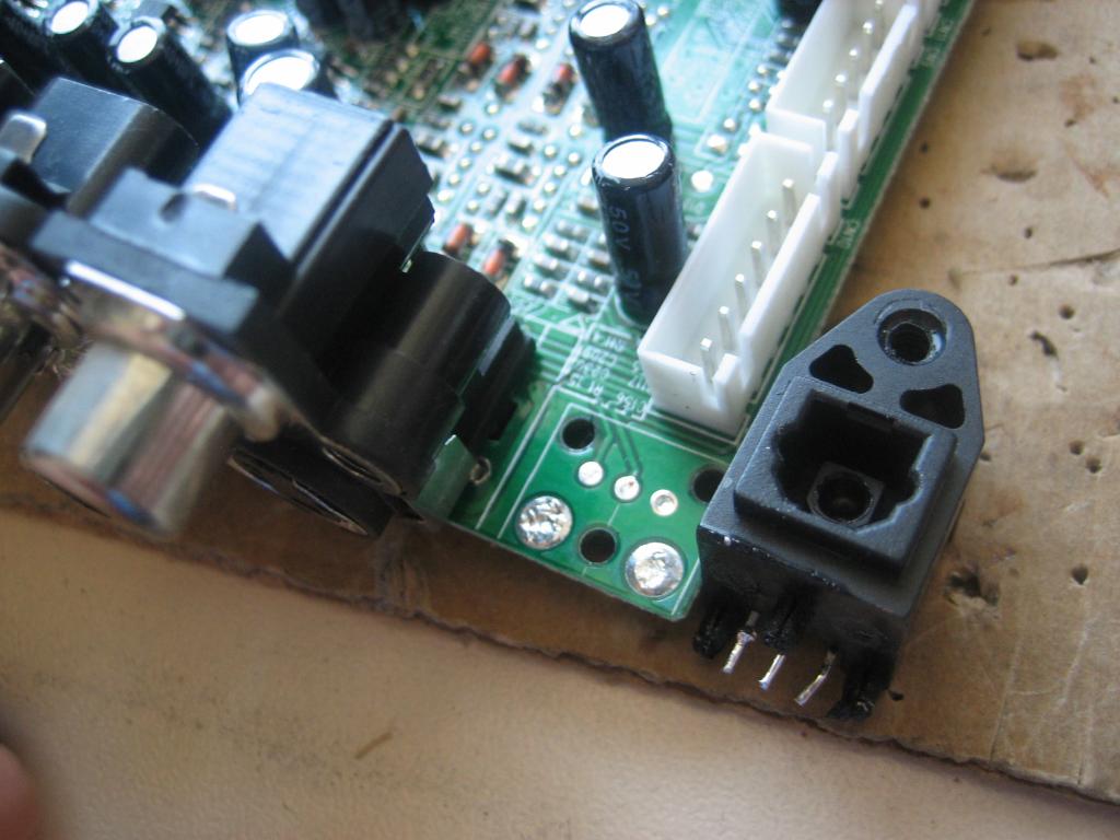
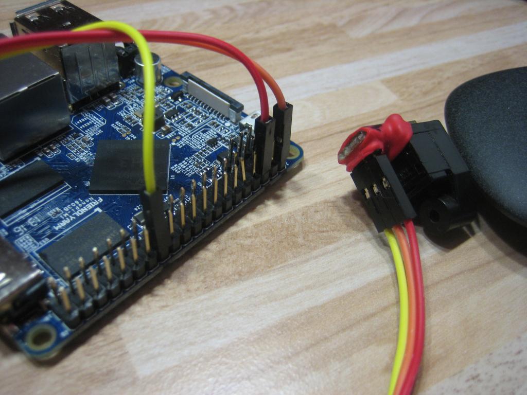
Here is a short instruction how to enable S/PDIF digital audio output on NanoPI M1 board running Debian Jessie with legacy kernel. This instruction can be applied to other H3 based boards but connect S/PDIF output hardware to GPIOA17 can be tricky (soldering miniature camera connector pins). Operations can be done over serial console or ssh. Login as root Get a .fex file and open it in editor: bin2fex /boot/script.bin /tmp/script.fex nano /tmp/script.fex Search a csi0 (camera) section an disable it: [csi0] vip_used = 0 Search a S/PDIF section and enable it: [spdif0] spdif_used = 1 Get the name of the file pointed by the /boot/script.bin link and convert modified .fex to it: ls -la /boot/script.bin ----- /boot/script.bin -> bin/nanopim1.bin fex2bin /tmp/script.fex /boot/bin/nanopim1.bin Open /etc/modules to instruct Jessie to load S/PDIF modules at boot: nano /etc/modules Add module names near the end of file: sunxi_spdif sunxi_spdma sndspdif sunxi_sndspdif Reboot system: sync reboot After reboot login as root again Get the list of ALSA devices available: aplay -l **** List of PLAYBACK Hardware Devices **** card 0: audiocodec [audiocodec], device 0: SUNXI-CODEC sndcodec-0 [] Subdevices: 1/1 Subdevice #0: subdevice #0 card 1: sndhdmi [sndhdmi], device 0: SUNXI-HDMIAUDIO sndhdmi-0 [] Subdevices: 1/1 Subdevice #0: subdevice #0 card 2: sndspdif [sndspdif], device 0: SUNXI-SPDIF sndspdif-0 [] Subdevices: 0/1 Subdevice #0: subdevice #0 To connect board S/PDIF output to my favorite DAC i use an optical S/PDIF module soldered out from dead DVD player: There are 3 wires connected to board 40-pin connector: GND (pin 6), VDD_5V (pin 2) and SPDIF-OUT/GPIOA17 (pin 26) Module pinout can be found in datasheet http://www.mouser.com/catalog/specsheets/totx177(f,t).pdf Modules come in 2 types: 6-MBit (up to 24 bit / 96KHz) and 15-MBit (up to 24 bit / 192KHz). Most likely from DVD or SAT receiver You get the 6-MBit module. 15-MBit modules can be purchased at Digikey, etc. When listening to music, I faced with spontaneous fadings. This is due to some problem of the CPU speed switching. To this do not happen, I banned the clock frequency of 240 MHz in the /etc/default/cpufrequtils: MIN_SPEED=480000
-
Questions and answers about powering the Orange Pi Zero using the "Power over Ethernet" option. The aim is to answer community questions about Power Over Ethernet options (both official 802.3af/at and unofficial "PoE" solutions) and to improve the wiki page with these answers: http://linux-sunxi.org/Xunlong_Orange_Pi_Zero Helpful links: http://linux-sunxi.org/Xunlong_Orange_Pi_Zero#Powering_the_board https://en.wikipedia.org/wiki/Power_over_Ethernet https://forum.armbian.com/index.php/topic/1762-new-oranges-with-h5-and-h2/page-2#entry19054 Examples of standards-compliant PoE hardware: 802.3af switch: https://www.amazon.com/TP-Link-8-Port-Ethernet-Desktop-TL-SF1008P/dp/B003CFATT2/ 100MBit 802.3af to 5V power supply (10W max): https://www.aliexpress.com/item/1PCS-Micro-USB-Active-POE-Splitter-Power-48V-to-5V-2-4A-for-Raspberry-pi-3/32741378583.html Gigabit 802.3af to 12/9/5V power supply (12W max): http://www.tp-link.com/en/products/details/cat-4794_TL-POE10R.html Examples of non-standards-compliant PoE hardware: 8 port "PoE" injector (you pick the input voltage): https://www.aliexpress.com/item/Cameye-8-Channel-CCTV-POE-Injector-for-Surveillance-IP-Cameras-Power-over-Ethernet-Adapter-with-Shell/32745669802.html "PoE" splitter: https://www.aliexpress.com/item/POE-Adapter-cable-Tape-Screened-Passive-Power-Over-Ethernet-RJ45-Injector-Splitter-Kit-12-48v-Synthesizer/32516398486.html https://www.aliexpress.com/item/10cm-3-9-5-5mm-x-2-1mm-DC-Female-to-Micro-USB-Male-Charging-Cable/32319957922.html (Zero soldering option!) Solder to pads on Orange Pi Zero and use a DC-DC step down converter to get 5V: https://www.aliexpress.com/item/5-pcs-Ultra-Small-Size-DC-DC-Step-Down-Power-Supply-Module-3A-Adjustable-Step-Down/32261885063.html https://www.aliexpress.com/item/15924-Free-shipping-DC-DC-Step-Down-Converter-Module-LM2596-DC-4-0-40-to-1/32354635261.html https://www.aliexpress.com/item/24V-12V-To-5V-5A-DC-DC-Buck-Step-Down-Power-Supply-Module-Synchronous-Rectification-Power/32689938167.html Q&A: 1. The Orange Pi Zero says it supports "PoE" how is this implemented? The Ethernet port on the Orange Pi Zero exposes pins 4/5 and 7/8 via pads on the bottom of the board. Photo here. Note that this is 802.3af mode B, which is not fully standards compliant (802.3af/at specifies mode A and mode B, it is not allowed to have a device which only accepts one mode). Out of the box, there is NO way to power the board from Ethernet, either with an 802.3af/at switch or with passive "PoE" injectors. More effort is needed. 2. What are the options to power the Orange Pi with "PoE" ? Option 1: Solder 0 Ohm resistors across the pads and use a PoE injector with 5V. Pro: + No additional power supply needed Con: - 5V cannot travel long distances without voltage sag. You can put in a higher voltage (e.g. 7V DC) but then all the cables would need to be the same length and you risk destroying the Orange Pi if the voltage spikes. Option 2: Solder a step-down converter and use a PoE injector with a higher voltage (e.g. 24V). Pro: + 24V will travel much farther than 5V in a CAT5/6 cable. Cons: - You will need to purchase and solder an additional voltage regulator to take the input voltage and drop it down to 5V. Option 3: Buy/use a PoE switch implementing 802.3af/at. Pro: + Standards compliant + 802.3af/at operate at ~48V, which can power devices up to 100m away from the switch + Plugging in a non-PoE device will not result in fireworks + Cable faults will not result in short circuits because the switch will shut down the port Con: - Power electronics to turn 48V into 5V may consume more power than the Orange Pi itself - More expensive
-
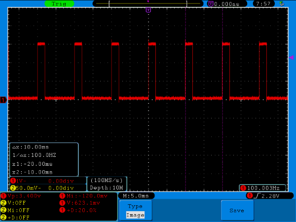
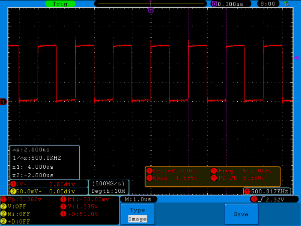
 Requirements Fresh enough nighly or manually built image Latest kernel and dtb packages (26.03.2017 or newer) Limitations As stated in other PWM related threads, hardware PWM output is supported only on pin PA5 which is also UART0 ("debug" serial console) RX pin, so enabling PWM will disable this console. Activation Add "pwm" to "overlays" line in /boot/armbianEnv.txt Example: overlays=pwm Reboot is required to apply the changes Armbian overlays documentation: https://docs.armbian.com/User-Guide_Allwinner_overlays/ PWM sysfs interface Official documentation: https://git.kernel.org/pub/scm/linux/kernel/git/stable/linux-stable.git/tree/Documentation/ABI/testing/sysfs-class-pwm?h=v4.10 Please note that this ABI is considered "testing" so it may change in the future. Sysfs interface example # activate the PWM. On H3 only 1 PWM is supported, so exporting PWM 0 echo 0 > /sys/class/pwm/pwmchip0/export # set period to 10ms echo 10000000 > /sys/class/pwm/pwmchip0/pwm0/period # set normal polarity. needs to be reset explicitly. Bug? echo "inversed" > /sys/class/pwm/pwmchip0/pwm0/polarity echo "normal" > /sys/class/pwm/pwmchip0/pwm0/polarity # enable the PWM echo 1 > /sys/class/pwm/pwmchip0/pwm0/enable # set duty cycle to 1ms echo 1000000 > /sys/class/pwm/pwmchip0/pwm0/duty_cycle Result: # set duty cycle to 2ms echo 2000000 > /sys/class/pwm/pwmchip0/pwm0/duty_cycle Result: # set duty cycle to 1us, period to 2us echo 1000 > /sys/class/pwm/pwmchip0/pwm0/duty_cycle echo 2000 > /sys/class/pwm/pwmchip0/pwm0/period Result: Please note that some settings needs to be changed in a correct sequence, i.e. you can't set duty cycle higher than period root@orangepiplus2e:~# echo 1000 > /sys/class/pwm/pwmchip0/pwm0/duty_cycle root@orangepiplus2e:~# echo 500 > /sys/class/pwm/pwmchip0/pwm0/period -bash: echo: write error: Invalid argument root@orangepiplus2e:~#
-
Is not important, and is a topic related to desktop environment and I know that armbian is more a server OS than a dektop replacement ... but I'm stuck trying to have all the environment in my mother language, Spanish. I change locale in root user and in the additionally created desktop user, I use dpkg-reconfigure locales locales and also export LANGUAGE=es_ES.UTF-8 but after reboot is again in English. And also when I update and upgrade the system I can see Translation-en logs but never a Translation-es. Is there any chance to do a better localization of the Desktop Environment? Thanks.
-
 Let's start with a weird image first: In the plastic box is an Olimex A20-Lime2, a 2.5" HDD with 2TB and Olimex' largest battery with 6600mAh. Mounted on the top cover (box standing on the side) is a Banana Pi M2+ (to be replaced with NanoPi M1 or OPi One/PC in the future) Why Lime2? Since this board from our friends at Olimex is designed intelligently and provides DC-DC step-up converters on the board providing the ability to power also the connected SATA disk when running from battery (unlike most other A10/A20 boards that do only provide 5V on USB ports in battery mode but not to the disk!). And since A20 is perfectly supported by mainline kernel (I run 4.6.4 on it with btrfs on both SD card and connected SATA disk. Since the Lime2 is used as monitoring/rsyslog host btrfs compression is active and the 2TB HDD might store up to 20TB of raw log/monitoring data) Why BPi M2+? Since board was lying around and I have no other use for it (SinoVoip sent me a review sample a while ago). The idea to combine A20 with a H3 device was simply to add a camera capable and performant device that is ultra cheap (does not apply to BPi M2+ but to NanoPi M1 or OPi One for example). The H3 device will be used to off-load some stuff (eg. OpenVPN encryption), to capture images and do other hardware monitoring (eg. checking temperature in server racks using 1-Wire sensors) Both boards in this mode run up to 8 hours on battery (6h when the 2 TB disk is also always spinning -- but I use a large 64GB Samsung EVO in the Lime2 and wake up the HDD only from time to time to move data over from SD card). And in this special mode the Lime2 is acting as UPS for the H3 board too since BPi M2+ is powered through Micro USB from Lime2's left USB type A receptacle. The same USB connection is also used as a 'private' network utilizing Ethernet gadget driver on the H3 device. BPi M2+ is running our sun8i legacy kernel, g_ether module is active and configuration using a link local address as outlined in this thread. Therefore as soon as BPi M2+ boots and brings up his usb0 interface the board appears as Ethernet USB dongle on the Lime2 and can be used easily with the following settings as directly connected network device (providing ~120 Mbits/sec throughput over the USB cable): This USB connection can now be used as a directly wired network connection (BPI M2+ is 169.254.2.1 and Lime2 169.254.2.2 and both can interact through this connection or use it as 'heartbeat' connection to monitor network outages). And using BPi M2+ or NanoPi M1 or NEO the very same USB connection can also be used to power the H3 device (not with Oranges there a hardware mod is needed). Now the fun part: In case the USB powered H3 device freezes or is shut down and has to be restarted... how to do so? Some/most A10/A20 boards provide the 5V on their USB ports not directly from DC-IN but through their AXP209 PMU. And if the board is designed that way, power can be switched on/off on request. This is where the sunxi-pio tool gets interesting since with this tool you can query and switch pin state. In the above example BPi M2+ is powered through Lime2's left USB port. VDD_USB of this port can be controlled through PH06 pin. So to cut power from Lime2 to BPi M2+ all I have to do is sunxi-pio -m PH06'<default><default<default><0>' And to provide power again, it's the opposite: sunxi-pio -m PH06'<default><default<default><1>' (at least on my Lime2 the left USB port is more reliable than the right port that can be controlled through PH03 pin). To be able to use the sunxi-pio tool you need a recent sunxi-tools version. As Armbian user you don't have to care since we ship always the most recent version. Not all A10/A20 boards support this and pin mappings differ between different boards. So where to look? In the fex files (don't trust them blindly, some vendors horribly suck providing documentation for their own hardware, compare the pin mappings in bananapiprolcd7.fex and bananapipro.fex for example). EDIT: Checked with both Banana Pi and Banana Pro: The USB voltage pin mappings in the fex files are plain BS and do not work (obviously 'copy&paste gone wrong' when they copied all of CubieTech's work in the beginning) I let a script check the fex files of all Allwinner boards we currently support. Two H3 devices show the ability to switch USB voltage (OPi 2 and Plus/Plus2 -- the pin here most probably controls power for the internal Terminus USB hub) but all the others are A10/A20 based: Edit: But at least on H3 Orange Pi boards it's possible to toggle power available on Micro USB port from userspace. So if you want to switch power on the USB ports of a Banana Pro you would not use PH03/PH06 but PH00/PH01 instead (and yes, sunxi-pio works with exactly these settings/syntax even when the board runs vanilla/mainline kernel). Since we're talking about A20 Bananas now: These devices do not provide power to a connected SATA disk when running on battery unlike Olimex' boards. So in case you want to ensure that a connected SATA disk keeps spinning when DC-IN is not available then you have to DIY a cable solution taking power from the 2 USB ports and feeding SATA power this way (the SATA power connector on Banana boards is directly wired to the Micro USB DC-IN jack so you can both provide DC-IN here more reliably and have to keep in mind that battery/AXP209 is not involved at all) BTW: sunxi-pio can be used for more than just switching power on USB ports. Simply call it without arguments to get the idea / help text. Anyone trying to decrease consumption of his Allwinner board might love this tool since you're able to switch off on-board consumers from user space.
 -
http://forum.odroid.com/viewtopic.php?f=138&t=20972