
Search the Community
Showing results for 'uart rts'.
-
Hello, I'm trying to connect a serial device on my nanopi neo plus2, but the gpio uart seems to be disable, please can you help me step by step? I found some things on forums but I understand nothing .... Thank you in advance
-
Additions: GPU node UART 1 & 5 nodes GPU is disabled by default as I am not 100% how functional it currently is. Checklist: Please delete options that are not relevant. [ ] My code follows the style guidelines of this project [ ] I have performed a self-review of my own code [ ] I have commented my code, particularly in hard-to-understand areas [X] My changes generate no new warnings [ ] Any dependent changes have been merged and published in downstream modules View the full article
-
Hi all I have a project need high uart baudrate, > 2Mbit/S, how can I get this work, seems the stty not work correctly
-
I have just installed an Armbian Jammy CLI on my BPI-CM4. I need to use the UART that is routed to pins 8 and 10 on the 40-pin connector (UART_EE_B in the BPI-CM4 schematics). I have enabled it in the device tree by changing this from disabled to okay: serial@23000 { compatible = "amlogic,meson-g12a-uart\0amlogic,meson-gx-uart"; reg = <0x00 0x23000 0x00 0x18>; interrupts = <0x00 0x4b 0x01>; clocks = <0x12 0x02 0x2a 0x12>; clock-names = "xtal\0pclk\0baud"; status = "okay"; phandle = <0x12b>; }; Once rebooted, and new UART appears (ttyAML6). However, it does not work. What am I missing? Thanks in advance
-
 Hello! I have installed Armbian Bookworm on Khadas VIM3. Also I have enabled "UARTa" , "UARTc" in armbian-config utility. After reboot in file /boot/armbienEnv.txt I have checked options about uart (uarc). Also there are many files /dev/ttyS[0-7] exists. After this I try to connect "minicom -D /dev/ttyS0" (ttyS0, S1, and S3 etc). But no answer from my device on pins 15,16 OR 18,19 (this is a UARTA,UARTC, UART linux). Python sripts pyserial output: "i/o error". Does Armbian (Bookworm or Jammy) supports Khadas VIM3 UART? Are there successful cases? One more question: On Ubuntu Server files /dev/ttyS* are absent. However Khadas supports UART (on https://docs.khadas.com/products/sbc/common/applications/gpio/uart ) Thank you!
 -
 I want to use the OPI3, but I need 2 uarts, in 26 headers there is 1 availabe, but I need one more. Is possible to disable the debug, and use it for my application?
 -
Hello Everyone, As I am still working on hardening my Odroid-M1 servers, I am looking for a solution to activate a real console for root login only. My homelab is not in the same room as my desk, so I need to get access from an internal VLAN with restrictions and take control even if the network drivers are not enabled. Have you tested or used a UART to Ethernet converter like https://www.pusr.com/products/ethernet-to-uart-modules-usr-k7.html or https://www.waveshare.com/uart-to-eth.htm or something else? Let me know your thoughts. Sincerely, Frederic
-
Hi all, I have an Armbian installed on Orange PI 4B. I am trying to connect a flight controller to Orange PI 4B by using UART port. This board has a 40 pin header. I went to armbian-config, and enabled the UART1 and UART 4 which are available from armbian-config. I plug the UART port (to Pin 8 and pin 10) on the 40 pin header. Is that port UART 4? I am not sure. It does not work. I tried the debug port, but the Orange PI does not start up if something is plugged in to the debug UART port. The PIN layout https://wiki.adopisoft.com/doku.php?id=4.0.0:gpio_numbering The layout of the board is similiar to Orange PI One. I know the 5 V location by using the case fan. Thanks,
-
Hi all, I need to enable rts/cts on my OrangePi Zero with Armbian buster with Linux 5.4.26-sunxi installed. I added the "param_uart2_rtscts=1" (I'm using /dev/ttyS2) to the /boot/armbianEnv.txt file On mi code I use this initialization of the port. xxxxx.c_cflag |= port_parity | port_bits | port_stop | CLOCAL | CRTSCTS | CREAD; Not only rts/cts but also the tx and rx pin aren't working now. Has anyone managed to enable the port on this board? Am I doing something wrong?
-
 rpi4b/bcm2711: introduce RPI_DEBUG_CONSOLE=yes which at once disables bt, enables uart, and adds ttyAMA0 Enabling uart debug on rpi4b requires a bunch of seemingly unrelated changes. The UART stuff on bcm is a bit cuckoo. View the full article
 -
Hello, I am trying to communicate using UART PORT. I have connected to 8, 10 and GND pin. Also I enabled UART3, but it doesn't work. Any solution? Thanks !! Enviado desde mi iPhone utilizando Tapatalk
-
Hello I'm new in Armbian. I'm trying to connect one Orange Pi Zero 2 to a 3d printer (board Cheetah v1.2) using UART in order to install Klipper to control the printer. I can't find how to enable the UART port to connect. I'm planning use UART 5 (pins PH2 PH3 according to this pinout http://www.orangepi.org/orangepiwiki/images/e/e3/Orange-pi-zero2-img4.png) . I've been searching for hours the right way to enable the UART communication, but I've not found a clear explanation about how to do it. I've trying armbian-config but Hardware option doesn't appears in the Menu. I'm using the Armbian_22.11.3_Orangepizero2_bullseye_legacy_4.9.318 image. Also, I've another question: I dont' know why but most of the images from the repository doesn't boot. The red ligth on the board never changes to green and of course i can't connect to the Opi. Why could be the reason? Thanks
-
Hello, Im trying to get 2 Uarts working on an Orange Pi Zero+2. Im using armbian Buster image for OPiZ+2 Linux orangepizeroplus2-h3 5.4.43-sunxi #20.05.2 SMP Mon Jun 1 18:26:22 CEST 2020 armv7l GNU/Linux I added UART1, UART2 and UART3 to armbianEnv.txt and was able to read / write on ttyS2 on pins 8 (PA00) and 10 (PA01). But couldnt find which pins ttyS1 or ttyS3 are on. I read at that UART 3 should be Tx PA13 Pin 24 Rx PA14 Pin 23 Is anyone able to suggest which pins I can use for a 2nd UART and is there a file I can look in to find the configuration for the UART Overlays ? Thanks Chris ______________________ Sorry, my mistake with wiring. ttyS3 does work on Tx PA13 Pin 24 Rx PA14 Pin 23 So armbian UART overlays working as required.
-
I have a box S905X SOC I want to use the universal asynchronous transceiver device to debug other devices what should I do TtyAML0 is used by the Console as a debug universal asynchronous transceiver and cannot be used.
-
 There is a armbian release for odroid n2+ but my request is for working release. Means working also onboard uart. At this moment no chance to get working uart which is on the odroid board.
 -
I'm testing the Armbian image for Odroid N2+ ( Armbian_22.08.7_Odroidn2_jammy_current_5.19.17_xfce_desktop) to see if it's a good migration path from the HardKernel base image. Unfortunately I need to get both i2c bus running on the GPIO and so far only the first bus seems to work (i2c-0). Looking into /sys/bus/i2c/devices , it looks like i2c-1 is tied to the hdmi port instead of the 2nd i2c bus on the GPIO : lrwxrwxrwx 1 root root 0 Dec 31 1969 0-0051 -> ../../../devices/platform/soc/ffd00000.bus/ffd1c000.i2c/i2c-0/0-0051 lrwxrwxrwx 1 root root 0 Dec 31 1969 i2c-0 -> ../../../devices/platform/soc/ffd00000.bus/ffd1c000.i2c/i2c-0 lrwxrwxrwx 1 root root 0 Dec 31 1969 i2c-1 -> ../../../devices/platform/soc/ff600000.bus/ff600000.hdmi-tx/i2c-1 I also tried to load the uart dtbo using armbian-config, but they do not show up in /dev after a reboot. so it looks like none of the overlay are actually loading. Here is the content of my armbianEnv.txt : verbosity=1 console=both overlay_prefix=meson bootlogo=true rootdev=UUID=9355737e-ddfc-4d22-a953-b2bb4bf41a56 rootfstype=ext4 overlays=g12-gxl-cma-pool-896MB i2cA i2cB uartA uartC usbstoragequirks=0x2537:0x1066:u,0x2537:0x1068:u so.. how do I enable the i2c port properly, as well as the uarts ... and I will need to also enable pwm on pin 12 and 33 (pwm_ef pwm_cd overlay on Hardkenel images). These is my current overlay line on Hardkernel images : overlays="i2c0 i2c1 uart0 uart1 pwm_ef pwm_cd" Thanks.
-
Hi, I have a odroid n2+ and I want ask, how to enable UART on the pin8 and pin10 ? Normaly it's mapped as ttyAML1 but this is now missing. I found some informations about /boot/armbianEnv.txt, but I'm not well experienced so I don't want beak a OS. Please can you help me what to modify to get UART working ? Thank you for help
-
I want to use a StromPi3 board with my lepotato board. I am using the armbian image. I used armbian-config to enable the serial ports and both show up as /dev/TTYAML0 and /dev/ttyAML6. Nonetheless I am unable to communicate on the serial ports even when connecting jumpers and a USB serial converter. I later tried to modify the divorce tree by hand. No change. Is there something else I could try to get the serial port on pins 8 and 10 working?
-
I'm using Banana Pi M2 Zero with Armbian Debian GNU/Linux 10 (Buster). Compiled the image myself with the latest source code using the armbin/build repository. I want to be able to do serial communication on pins 8 and 10. I'm looking for something to appear at /dev/ttyAMA0, so I can communicate with it. I saw some other forum posts which mentioned it'll happen on /dev/ttyS0 , however even that is not happening. The serial communication is working via FTDI (using the USB side connected to the Banana Pi), which indicates there is no problem with the other device. This is what the configuration looks like using "sudo minicom -s". +-----------------------------------------------------------------------+ | A - Serial Device : /dev/ttyS0 | | B - Lockfile Location : /var/lock | | C - Callin Program : | | D - Callout Program : | | E - Bps/Par/Bits : 115200 8N1 | | F - Hardware Flow Control : No | | G - Software Flow Control : No | | | | Change which setting? | +-----------------------------------------------------------------------+ | Screen and keyboard | | Save setup as dfl | | Save setup as.. | | Exit | | Exit from Minicom | +--------------------------+ I have enabled "uart1" using "sudo armbian-config -u" -> System -> Hardware. Connecting Rx, Tx on the pins 8 and 10 also does not show up in "dmesg" How do I go about debugging the issue or finding the root cause of the problem? Many thanks!
-

Garbage voice from the UART to USB with Orange PI 3 LTS
Emir Özmen posted a topic in Allwinner sunxi
Hi everyone, I connected my board with my PC via serial USB. Then I opened a serial with minicom and tried to test it out. I can send the strings from my board to PC without any problems but when I write something on the PC it sends garbage to my board. But, if I connect the TX, RX like: TX->TX RX->RX instead of TX->RX, RX->TX it sends normal from the PC and garbage from the board. I checked my baud rates but everything seems legit. I tried both 9600, 115200 bit rates, I also tried the both voltages (5V, 3.3V) What do you think could cause this problem? I saw this thread but seems like there are no solution so far. I would really appreciete it if you can help me out. -
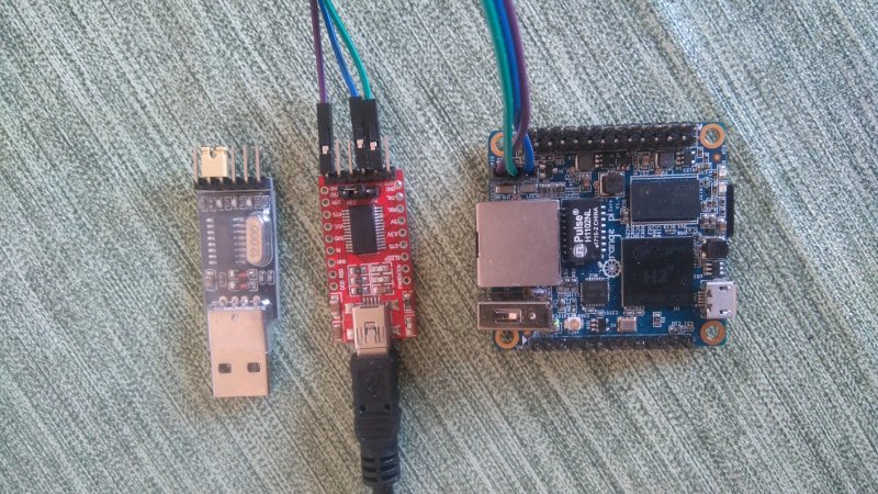
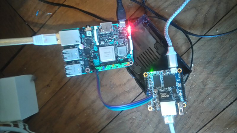
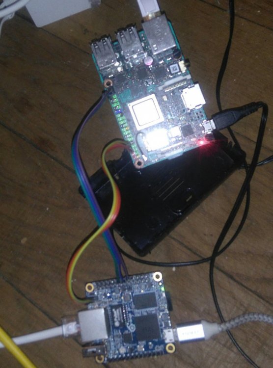
 Access to a console can be mandatory when you SBC doesn't work as expected (e.g Network or HDMI output doesn't work). When SSH/Display access isn't possible access to console via UART is the best way to get a clue where your SBC hangs. This short tutorial should give you an introduction how this works. For some boards, armbian implements an USB gadget mode (a 'fake' serial console over microUSB) describen below. As a reminder an USB-UART bridge is always prefered over USB gadget mode whenever possible (UART get's initialized before the gadget driver and also before HDMI, means even if you don't get a proper output from HDMI or gadget mode console, it is possible that UART will give you the needed information). Prerequisites: We need an Terminal program to access the console. If you use Linux on your host system I prefer picocom (something like minicom will also do the job) which can be installed: on debian a like systems: sudo apt-get install picocom from arch community repo: https://www.archlinux.org/packages/community/x86_64/picocom/ on fedora systems: yum install picocom on Mac OS X: brew install picocom on Widows we use PuTTY: https://www.chiark.greenend.org.uk/~sgtatham/putty/latest.html UART USB Adapter: There are various USB-UART bridges e.g FT232 (and fakes of them, cause FDTI is expensive ), CH340/1,PL2303 or CP2102 Normally it doesn't matter which one you use. I prefer the (probably fake) FDTI on the right side, but the CH341 does also a good job: The only thing which is needed is that the signal-level matches with your SBCs needs (this is mostly 3.3V expect some Odroids e.g HC1 which has only 1.8V!). Most of these USB-UART bridges have jumpers for 5V and 3.3V, make sure that you use the 3.3V. You've to figure out which pins on your SBC are debug UART (they've mostly a own 3 pin header, sometimes it's on the large pin header e.g. Tinkerboard) and then connect: GND --> GND RX --> TX TX --> RX You've to check dmesg (linux) or run devmgmt.msc (windows) to know which device you use. Linux: [256597.311207] usb 3-2: Product: USB2.0-Serial [256597.402283] usbcore: registered new interface driver ch341 [256597.402341] usbserial: USB Serial support registered for ch341-uart [256597.402392] ch341 3-2:1.0: ch341-uart converter detected [256597.404012] usb 3-2: ch341-uart converter now attached to ttyUSB0 --> Device will be /dev/ttyUSB0 Windows: for windows 10 (https://www.google.ch/search?client=opera&q=find+arduino+port+windows+10&sourceid=opera&ie=UTF-8&oe=UTF-8) Something like the picture in USB Gadget Mode part of the tutorial should show up) Armbians default settings are (expect some RK devices): For Picocom: picocom -b 115200 -r -l /dev/ttyUSB0 and for some RK devices: picocom -b 1500000 -r -l /dev/ttyUSB0 For PuTTY: You've to set configuration in 'Serial'. COM11 is just an example and needs to be checked first, Speed (baud) needs to be changed when you deal with the few RK boards which need 1500000. OS X: TBD should be similar to Linux whereas the naming differs a bit. See: https://forum.odroid.com/viewtopic.php?f=53&t=841 as an example with minicom. Normally you connect the USB-UART bridge to your host computer (and the SBC) and start picocom/putty before you power the board to ensure you get the full bootlog and not only parts of it. USB Gadget Mode Several board (see list) for which official armbian images exist (or csc images can be built) have no HDMI display. On those boards there's USB gadget mode driver activated so that you can have console access to them via USB connection. The following short tutorial describes how you can access to console from Linux (don't have a windows machine here at the moment, I may check it later): install picocom connect your board via USB to your host computer (it should be one which is able to power an SBC via its USB port) check dmesg for the device showing up: [184372.603816] usb 3-2: Product: Gadget Serial v2.4 [184372.603818] usb 3-2: Manufacturer: Linux 4.14.65-sunxi with musb-hdrc [184372.660041] cdc_acm 3-2:2.0: ttyACM0: USB ACM device [184372.660402] usbcore: registered new interface driver cdc_acm [184372.660403] cdc_acm: USB Abstract Control Model driver for USB modems and ISDN adapters connect to it via picocom (in this case 'picocom /dev/ttyACM0'): chwe@chwe-acer:~$ picocom /dev/ttyACM0 picocom v2.2 port is : /dev/ttyACM0 flowcontrol : none baudrate is : 9600 parity is : none databits are : 8 stopbits are : 1 escape is : C-a local echo is : no noinit is : no noreset is : no nolock is : no send_cmd is : sz -vv receive_cmd is : rz -vv -E imap is : omap is : emap is : crcrlf,delbs, Type [C-a] [C-h] to see available commands Terminal ready Debian GNU/Linux 9 orangepizero ttyGS0 orangepizero login: root Password: You are required to change your password immediately (root enforced) Changing password for root. (current) UNIX password: I assume if you use the same settings in something like putty on windows and you check which 'serial' device shows up in *where windows shows connected devices - I forgot it* you should be able to access it from windows (someone motivated may confirm this). For Windows: run devmgmt.msc and search for the serial device (in this case COM3) and connect to it via PuTTY (thanks to @hjc): for windows 10 (https://www.google.ch/search?client=opera&q=find+arduino+port+windows+10&sourceid=opera&ie=UTF-8&oe=UTF-8): (even the tutorial is for arduinos, it should be similar for every 'COM device') Currently boards with USB gadget mode: bananapim2plus bananapim2zero nanopifire3 nanopim3 nanopineo2 nanopineocore2 nanopineoplus2 orangepizeroplus nanopiair nanopiduo nanopineo olimex-som204-a20 orangepilite orangepi-r1 orangepizero orangepizeroplus2-h3 orangepizeroplus2-h5 tritium-h3 The silly approach For those, who want to save 1$ for an USB-UART bridge, you can spend 10$ for an OrangePi Zero and use its spare UARTs to log into an other SBC... SSH --> opi, ttl --> Tinkerboard For those loving text more than videos: SSH to your SBC sudo armbian-config --> system --> hardware to activate an spare UART (in this case it was UART2, will give you ttyS2) reboot picocom -b 115200 -r -l /dev/ttyS2 See: https://asciinema.org/a/B87EOGhc0gx9oikMAGEG94lXR
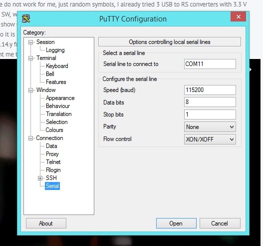
-
Description This PR adds some missing overlays of Orange Pi 5 that doesn't exists on Radxa's kernel source. I didn't add pwm13-m2 and pwm14-m1 because of they were already exists. How Has This Been Tested? [x] Checked availability of PWM, I2C, SPI, UART from /dev. Checklist: [x] My code follows the style guidelines of this project [x] I have performed a self-review of my own code [x] I have commented my code, particularly in hard-to-understand areas [x] I have made corresponding changes to the documentation [x] My changes generate no new warnings [x] Any dependent changes have been merged and published in downstream modules View the full article
-
Not sure if the rolling release includes the UART dtb yet, but when I build my own image (jammy xfce kernel 5.10.110) I don't have the UART dtbs in /boot/dtb/rockchip/overlay/ . As a result, I couldn't add uart0-m2 to /boot/armbianEnv.txt and get /dev/ttyS0 when I was following the official user manual to enable UART. After some researching I managed to solve this by copying the dtb file from orange pi's official ubuntu image to /boot/overlay-user and enable UART with user_overlays=rk3588-uart0-m2 in armbianEnv.txt . Rebooted and it works. However, I suppose it would be better to include the dts files in kernel patches? I'm posting this because I don't know what's the best practice for this.
-
Good day Please, tell me, how I can add RTS pin (flow control) to Uart in Orange Pi One ? It need me for control Uart-RS485 converter
-
I am in the process to migrate a project from a Raspberry Pi 4B to a Rock Pi 4B+. Among others external devices shall be connected via WiFi AP, I2C, 1-Wire and UART to the Rock Pi. To emphasis, the system is running healthy on a Rasberry. I managed to get WiFi AP and 1-Wire up and running on the Rock Pi. Now I got stuck with UART/UART4. Armbian 22.11.1 Bullseye with Linux 5.15.80-rockchip64 I enabled UART4 via Armbian-Config. Therefore, /boot/armbianEnv.txt shows: ... overlays=i2c7 uart4 w1-gpio param_w1_pin=GPIO4_D6 param_w1_pin_int_pullup=1 ... I can take a jump wire and bridge the TX-pin (GPIO1_B0, Pin#19) and RX-pin (GPIO1_A7, Pin#21). When sending bytes to the TX-pin I am receiving them instantly on the RX-Pin. That indicates to me the UART4 is working. On my system the serial port is /dev/ttyS4, with a baud rate of 1000!!. (I am doing this test via Node Red using a standard serial node) However, if I connect my TTL-signal cable to the RX-pin (TX disconnected), I do not see anything the RX-Pin (however this setup works on the Rasberry). I have done the same test on UART (/dev/ttyS2) with same result, not showing anything. I have no experience in Armbian or Rock Pi and would appreciate any hint into which direction to look. Is the unusual baud rate of 1000 a problem, or do I need some pull-up resistors or do I need to compile another dtbo driver like for the 1-wire?


