Search the Community
Showing results for 'gpio'.
-
Hi, anyone have already connected a speaker to gpio of lcpi h3 v8 (like orange pi pc). I have tried but im not sure if i2s is enabled on armbian
-
Armbian Version BOARD=bananapif3 BOARD_NAME="BananaPi BPI-F3" BOARDFAMILY=spacemit BUILD_REPOSITORY_URL=https://github.com/armbian/build BUILD_REPOSITORY_COMMIT=2f1fa5f40 LINUXFAMILY=spacemit ARCH=riscv BOOT_SOC= IMAGE_TYPE=nightly BOARD_TYPE=csc INITRD_ARCH=riscv KERNEL_IMAGE_TYPE=Image KERNEL_TARGET=current KERNEL_TEST_TARGET= FORCE_BOOTSCRIPT_UPDATE= FORCE_UBOOT_UPDATE= OVERLAY_DIR="" VENDOR="Armbian" VENDORDOCS="https://docs.armbian.com" VENDORURL="https://www.armbian.com/" VENDORSUPPORT="https://forum.armbian.com" VENDORBUGS="https://www.armbian.com/bugs" VERSION=25.5.0-trunk.52 REVISION=25.5.0-trunk.52 BRANCH=current I tried to enbale the I2C bus according followig documentation - but it didn't work for me. https://forum.banana-pi.org/t/bananapif3-gpio-wiringpi-gpiod-python3-periphery-adafruit-blinka-and-luma-examples/18948 https://paste.armbian.de/furuzimipu [ 0.535367] /soc/i2c@d401d800/spm8821@41: Fixed dependency cycle(s) with /soc/i2c@d401d800/spm8821@41/regulators/DCDC_REG5 [ 0.558741] raid6: int64x8 gen() 1179 MB/s [ 0.559346] spacemit-regulator spacemit-regulator@spm8821: DMA mask not set [ 0.599031] /soc/i2c@d401d800/spm8821@41: Fixed dependency cycle(s) with /soc/i2c@d401d800/spm8821@41/regulators
-

Help wanted to test a new OpenVFD alternative
jock replied to Jean-Francois Lessard's topic in Amlogic meson
I would say, and I bet @Jean-Francois Lessard agrees, that is not a matter of "messing with my code" thing, but rather a matter of principles. A kernel module is supposed to do a kernel module or, In simple words, it interfaces the kernel with the hardware. The kernel means are to give the userspace a way to access the hardware. The module should not run any user business (eg: display something user-specific at boot/shutdown/whatever), but should in turn provide a service for the userspace to control the hardware. That's a simple principle in software engineering that's called "separation of responsibility", and is generally considered a good habit to agree with that principle. By the way, if your board has one or more colored leds, they are generally set up in the device tree and access basic GPIO system, so they are turned on as soon as the kernel starts. -
I have currently this on SD-card: root@rock3a:~# ls -1 /boot/vmlinuz-* /boot/vmlinuz-5.10.160-39-rk356x /boot/vmlinuz-6.12.12-current-rockchip64 /boot/vmlinuz-6.13.1-edge-rockchip64 /boot/vmlinuz-6.1.99-vendor-rk35xx Only with the 5.10 kernel from Radxa, I get both NVMe and SATA when I use the overlay 'rock-3a-sata.dtbo'. With 6.12 and 6.13, there is only SATA, no NVMe. 6.1 lets the kernel/board crash, I have not further looked into that. So I can reliably use the SATA HDD, also hd-idle spindown works, I monitor the powerconsumption per day on 12V level and it is great. So as a slow clone/backup NAS it works and is acceptable. But ultimate plan is to make it a fast/main NAS, using the NVMe as cache and also for OS, so only SPI+NVMe+SATA. 5.10 kernel lacks various Btrfs features, so that is a no-go. I need at least 6.1, although I know weird virtualization tricks to get it to work on a functional level, but then also, I might hit issues with KVM on the Radxa rk356x kernel. I got the kernel from: https://radxa-repo.github.io/bookworm/files.list Regarding power, I now use 12V as base (common GND), feed 12V into the Rock3A USB-C connector and 3.5inch 12V pin on HDD and tap 5V from Rock3A GPIO and that feeds the 5V pin of the HDD. As said, that works very nice and stable. So it still looks like the 'rock-3a-sata.dtbo' overlay 'hides/disables all PCIe', where it should not do anything with the PCIe3x2 where the NVMe is on. I saw this: https://patchwork.kernel.org/project/linux-rockchip/patch/20250106100001.1344418-2-amadeus@jmu.edu.cn/ but not sure if it is related.
-

TX95 Max - Allwinner H618 Quadcore Cortex - A53
Mark Waples replied to Mark Waples's topic in Allwinner CPU Boxes
Hmm the plot thickens dmesg | grep Open - gives me this - so it's not finding the vfd.conf file and is looking in the Device Tree for instructions as a fallback - so where does this vfd.conf file go? [ 14.228662] OpenVFD: Version: V1.4.4 [ 14.228681] OpenVFD: vfd_gpio_clk: Empty. [ 14.228686] OpenVFD: vfd_gpio_dat: Empty. [ 14.228691] OpenVFD: vfd_gpio_stb: Empty. [ 14.228698] OpenVFD: vfd_gpio0: #0 = 0x00; #1 = 0x00; #2 = 0xFF; [ 14.228704] OpenVFD: vfd_gpio1: #0 = 0x00; #1 = 0x00; #2 = 0xFF; [ 14.228711] OpenVFD: vfd_gpio2: #0 = 0x00; #1 = 0x00; #2 = 0xFF; [ 14.228718] OpenVFD: vfd_gpio3: #0 = 0x00; #1 = 0x00; #2 = 0xFF; [ 14.228724] OpenVFD: vfd_gpio_protocol: #0 = 0x00; #1 = 0x00; [ 14.228728] OpenVFD: vfd_chars: Empty. [ 14.228733] OpenVFD: vfd_dot_bits: Empty. [ 14.228738] OpenVFD: vfd_display_type: Empty. [ 14.228749] OpenVFD: Detected gpio chips: 300b000.pinctrl, 7022000.pinctrl. [ 14.228753] OpenVFD: Failed to verify VFD configuration file, attempt using device tree as fallback. [ 14.237971] OpenVFD: openvfd_gpio_clk: pin = 267, flags = 0x00 [ 14.237998] OpenVFD: openvfd_gpio_dat: pin = 268, flags = 0x00 [ 14.238004] OpenVFD: openvfd_gpio_stb pin entry not found [ 14.238009] OpenVFD: openvfd_gpio0 pin entry not found [ 14.238013] OpenVFD: openvfd_gpio1 pin entry not found [ 14.238017] OpenVFD: openvfd_gpio2 pin entry not found [ 14.238021] OpenVFD: openvfd_gpio3 pin entry not found [ 14.238025] OpenVFD: chars_prop = 00000000a90cb56d [ 14.238033] OpenVFD: chars_prop->length = 5 [ 14.238036] OpenVFD: char #0: 2 [ 14.238040] OpenVFD: char #1: 1 [ 14.238044] OpenVFD: char #2: 2 [ 14.238048] OpenVFD: char #3: 3 [ 14.238052] OpenVFD: char #4: 4 [ 14.238057] OpenVFD: dot_bits_prop = 000000008d579c57 [ 14.238061] OpenVFD: dot_bits_prop->length = 7 [ 14.238065] OpenVFD: dot_bit #0: 0 [ 14.238070] OpenVFD: dot_bit #1: 1 [ 14.238073] OpenVFD: dot_bit #2: 3 [ 14.238077] OpenVFD: dot_bit #3: 2 [ 14.238081] OpenVFD: dot_bit #4: 4 [ 14.238085] OpenVFD: dot_bit #5: 5 [ 14.238089] OpenVFD: dot_bit #6: 6 [ 14.238094] OpenVFD: display.type = 0, display.controller = 3, pdata->dev->dtb_active.display.flags = 0x00 [ 14.238531] OpenVFD: Select FD650 controller [ 14.238612] OpenVFD: SW I2C interface intialized (address = 0x0000 (N/A), MSB mode, pull-ups off) -

Help wanted to test a new OpenVFD alternative
dfahren replied to Jean-Francois Lessard's topic in Amlogic meson
@Jean-Francois Lessard You won't believe it, but I found my error(s) .... For the solution I had to look at the dts Paolo (https://github.com/paolosabatino/leds-fd6551) suggested in his code. I missed a line that effectively makes SDA really open-drain. However, pinctrl is not relevant in this context. The fist line is bloody important, the second not so: i2c-gpio,sda-output-only; i2c-gpio,scl-output-only; Although they do incur warnings in the kernel log, they are indispensable because without them, i2c signals don't reach the fd6551 controller. Now everything works as expected. It shows (in fact, it showed ...) 88:88 right at the start and after that the actual time. Great! I'm going to write a pull request for Nicolas' Github repo so that he can integrate it with the Armbian distribution. I also edited your tm16xx source code to show 'boot' instead of 88:88, which is not my cup of tea. You also have to make sure you compile the driver als built-in and not as a kernel object. So you get the 'boot' writing roughly around second 2.8 in the boot process when plugging in the mains adapter and this is early enough for me. I attach all of the sources to this post. I hope you don't mind too much that I messed with your code and I apologize upfront. Best wishes, Deetsh tm16xx_boot.c display-client-snippet.dts -
NB - evtest does not come with Armbian Bookworm. A quick "apt install evtest" and we're away! root@radxa-e20c:~# evtest /dev/input/event0 Input driver version is 1.0.1 Input device ID: bus 0x19 vendor 0x1 product 0x1 version 0x100 Input device name: "gpio-keys" Supported events: Event type 0 (EV_SYN) Event type 1 (EV_KEY) Event code 185 (KEY_F15) Key repeat handling: Repeat type 20 (EV_REP) Repeat code 0 (REP_DELAY) Value 250 Repeat code 1 (REP_PERIOD) Value 33 Properties: Testing ... (interrupt to exit) Event: time 1739040710.916095, type 1 (EV_KEY), code 185 (KEY_F15), value 1 Event: time 1739040710.916095, -------------- SYN_REPORT ------------ Event: time 1739040711.050330, type 1 (EV_KEY), code 185 (KEY_F15), value 0 Event: time 1739040711.050330, -------------- SYN_REPORT ------------ Do you know where I can find information on how to change settings for this button?
-
You can use "evtest /dev/input/event0" to analyze its output. Docs for gpio-leds: https://www.kernel.org/doc/Documentation/devicetree/bindings/leds/common.yaml https://www.kernel.org/doc/Documentation/devicetree/bindings/leds/leds-gpio.txt
-
TY for your reply. They definitely can be controlled by echoing values to the `/sys/class/leds/` and even though the "trigger" is set to "netdev" and tx and rx files appear, I'm not seeing any activity on those LEDs with network activity. I can manually make the LEDs blink by doing something like echo heartbeat > /sys/class/leds/lan-led/trigger cat /sys/class/leds/lan-led/trigger will show the available triggers, and a [] around the currently selected one. cat trigger none usb-gadget usb-host rc-feedback bluetooth-power rfkill-any rfkill-none kbd-scrolllock kbd-numlock kbd-capslock kbd-kanalock kbd-shiftlock kbd-altgrlock kbd-ctrllock kbd-altlock kbd-shiftllock kbd-shiftrlock kbd-ctrlllock kbd-ctrlrlock mmc0 timer oneshot disk-activity disk-read disk-write ide-disk mtd nand-disk heartbeat backlight gpio cpu cpu0 cpu1 cpu2 cpu3 activity default-on transient flash torch panic [netdev] mmc1 It looks very configurable, just doesn't seem to be "automatically" working to show network activity.
-
@Meestor_X From what I can see in the schematic for the E20C, the Ethernet LEDs are wired directly to the Ethernet controller chip. Can not be accessed by the SoC/OS via GPIO, therefore there is nothing you can do to control their behavior. However I would think that it should just work out of the box, so there is nothing you need to do either. If it doesn't work then I dunno, ask Radxa or something
-
Help wanted to test a new OpenVFD alternative
dfahren replied to Jean-Francois Lessard's topic in Amlogic meson
@Jean-Francois Lessard Thanks for your comprehensive answers. They helped me a lot, but as ill luck would have it, new questions arose ... As far as I can tell, the driver is loaded at second 2.7, which is perfectly early enough for me. Once the driver is ready to operate 8888 should be visible. Well, should .. I managed to get it running once and then I changed the config or the board dts or whatever and I never reached this state again, what a sh*t! May be you can spot any error in the dts, but I have the feeling that the error lurks somewhere else. You are so right, one can comment accurately on my questions if there is no dts you can look at. This time I attach my full dts to this post, promised. BTW, like I said before, I have an H96 Max V56, which has an FD6551 on the board. So there is no confusion. Rest assured, brightness is behaving as expected but is waaay to dark for me. If only those leds had white color ... Well I have made the led display "brighter" in a rather unconventional way -> I used a saw and sawed out a little rectangle from the front. Maybe my tv box doesn't look as pleasing as before, but the led display is much brighter now. Form follows function , ya know?! 🤣 Since the led display did work once, I think both SDA and SCL are configured correctly. i2c-6 is, in fact, the i2c node the kernel assigned to the tm16xx driver. When my tv box starts, somewhere in the kernel log I get i2c-gpio display-client: using lines 12 (SDA) and 11 (SCL) ... tm16xx 6-0024: Failed to set brightness: -6 tm16xx 6-0024: Failed to initialize display: -6 (-6 is ENXIO -> no device) The driver simply is unable to talk to the chip and I really don't know why. BTW my kernel has version 6.12.12 and the tm16xx is not built in but is a .ko Understood, I tried them and they worked, but thanks for the explanation (I found them earlier on your Github pages.) Yep, later. Led display isn't working right now ... 🙂 I have the feeling that using pinctrl would necessitate a "slight" rewrite of your driver and at the moment my inclination to go down this rabbit hole is, well, limited... But the question is,if there is a pinctrl definition regarding these two GPIO lines, will this definition interfere with the definition of the gpio lines in the display-client section? When using pinctrl I couldn't find any way to set the baud rate used for the communication. Is it unnecessary or is there some sort of auto-negotiation? So if you have any idea how I can arrive at a working led display again, please(!) let me know. Currently I'm at my wits end. All the best, Deetsh P.S.: oh, there is one thing I need to ask you: Do you know a way to make testing new versions of the dts easier than building an image and downloading in the emmc? myboard.dts -
Hi, I got my recording from Headphone Mic fixed. Here is what I make work for me: a) have pinctrl-0..2 set in the i2s0 b) make sure the reg=0x11 for the i2c1-codec c) add the Mic Bias. Tested with 6.12.12 which got a fix es8316 codec. &i2s0 { status = "okay"; pinctrl-names = "mclk", "bclk_on", "bclk_off"; pinctrl-0 = <&i2s_8ch_mclk>; pinctrl-1 = <&i2s0_8ch_bus>; pinctrl-2 = <&i2s0_8ch_bus_bclk_off>; resets = <&cru SRST_I2S0_8CH>, <&cru SRST_H_I2S0_8CH>; reset-names = "reset-m", "reset-h"; rockchip,playback-channels = <2>; rockchip,capture-channels = <2>; #sound-dai-cells = <0>; }; &i2c1 { status = "okay"; i2c-scl-rising-time-ns = <300>; i2c-scl-falling-time-ns = <15>; clock-frequency = <200000>; es8316c_codec: audio-codec@11 { compatible = "everest,es8316"; reg = <0x11>; #sound-dai-cells = <0>; clocks = <&cru SCLK_I2S_8CH_OUT>; clock-names = "mclk"; status = "okay"; }; }; es8316c_card: es8316c-card { compatible = "simple-audio-card"; pinctrl-names = "default"; pinctrl-0 = <&hp_det>; simple-audio-card,format = "i2s"; simple-audio-card,name = "rockchip-es8316c"; simple-audio-card,mclk-fs = <256>; simple-audio-card,hp-det-gpio = <&gpio4 RK_PD4 GPIO_ACTIVE_HIGH>; simple-audio-card,widgets = "Microphone", "Mic Jack", "Headphone", "Headphones"; simple-audio-card,routing = "Mic Jack", "Mic Bias", "MIC1", "Mic Jack", "Headphones", "HPOL", "Headphones", "HPOR"; simple-audio-card,cpu { sound-dai = <&i2s0>; }; simple-audio-card,codec { sound-dai = <&es8316c_codec>; }; };
-
Works for me... Here's some code that uses it to get the readings from a DHT11 sensor. /* * temphumid.c: * Read Temperature / Humidity from DHT11 sensor * -iGNUiCould */ #include <wiringPi.h> #include <stdio.h> #define MAX_TIMINGS 85 #define DHTPIN 7 // GPIO pin for DHT11 data int data[5] = {0, 0, 0, 0, 0}; // Function to read data from DHT11 void readDHT11() { uint8_t lastState = HIGH; uint8_t counter = 0; uint8_t j = 0, i; data[0] = data[1] = data[2] = data[3] = data[4] = 0; // Send start signal to DHT11 pinMode(DHTPIN, OUTPUT); digitalWrite(DHTPIN, LOW); delay(18); digitalWrite(DHTPIN, HIGH); delayMicroseconds(40); pinMode(DHTPIN, INPUT); // Read data from DHT11 for (i = 0; i < MAX_TIMINGS; i++) { counter = 0; while (digitalRead(DHTPIN) == lastState) { counter++; delayMicroseconds(1); if (counter == 255) { break; } } lastState = digitalRead(DHTPIN); if (counter == 255) { break; } // Ignore first 3 transitions if ((i >= 4) && (i % 2 == 0)) { data[j / 8] <<= 1; if (counter > 16) { data[j / 8] |= 1; } j++; } } // Verify checksum and print data if valid if ((j >= 40) && (data[4] == ((data[0] + data[1] + data[2] + data[3]) & 0xFF))) { float humidity = data[0] + data[1] / 10.0; float tempC = data[2] + data[3] / 10.0; float tempF = tempC * 9.0 / 5.0 + 32; printf("Temperature = %.1f°F\n", tempF); printf("Humidity = %.1f%%\n", humidity); } else { printf("Data not valid\n"); } } int main() { if (wiringPiSetup() == -1) { printf("WiringPi setup failed\n"); return -1; } while (1) { readDHT11(); delay(2000); // Wait 2 seconds before reading again } return 0; }
-
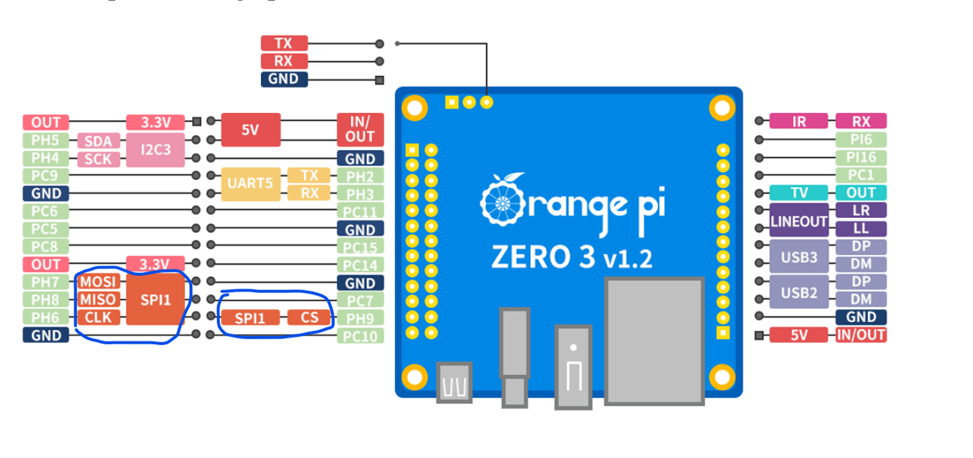
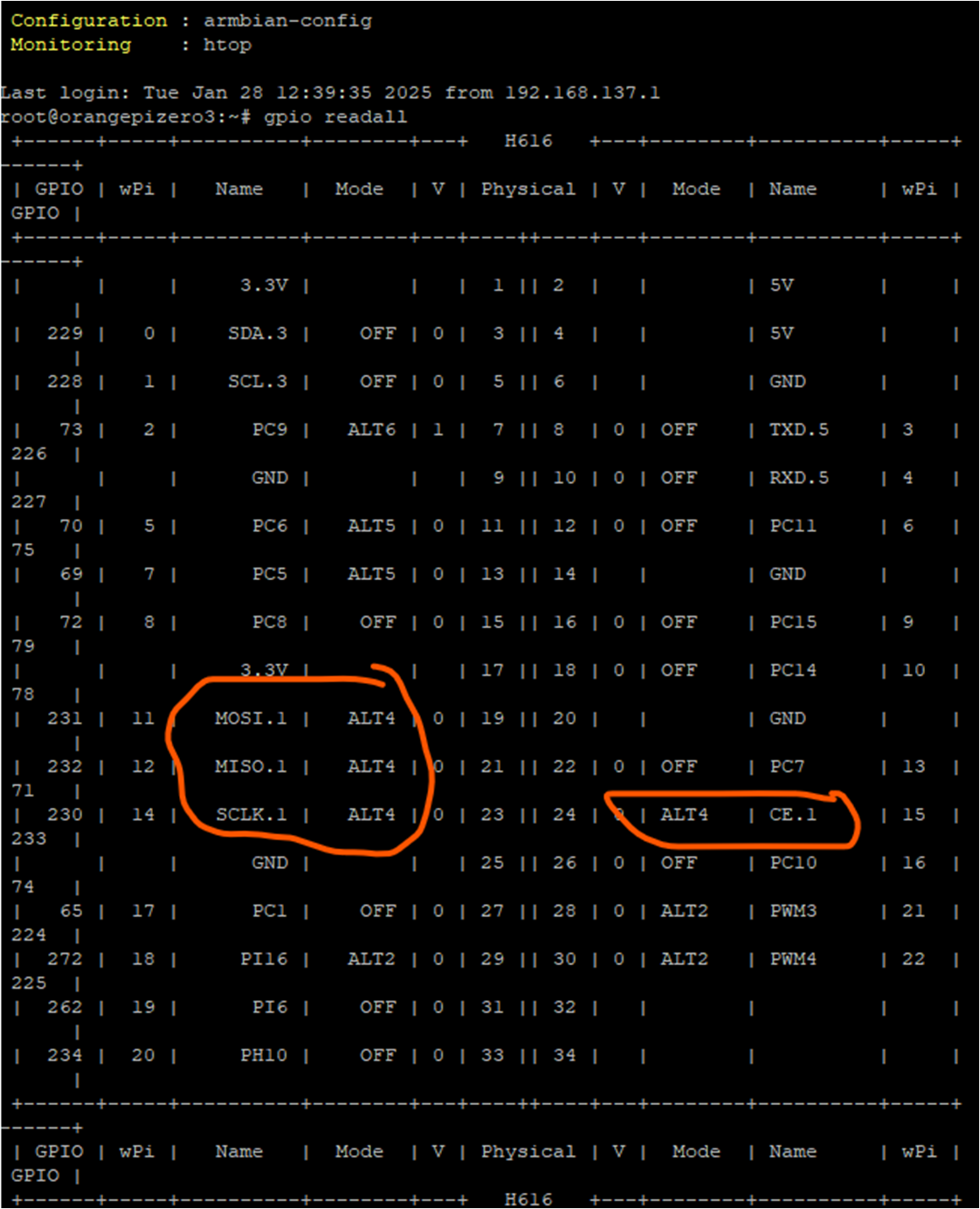
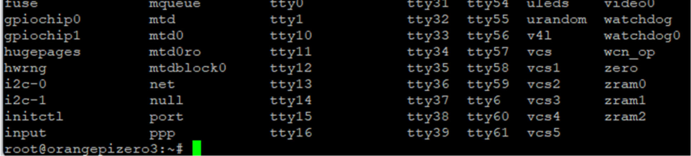
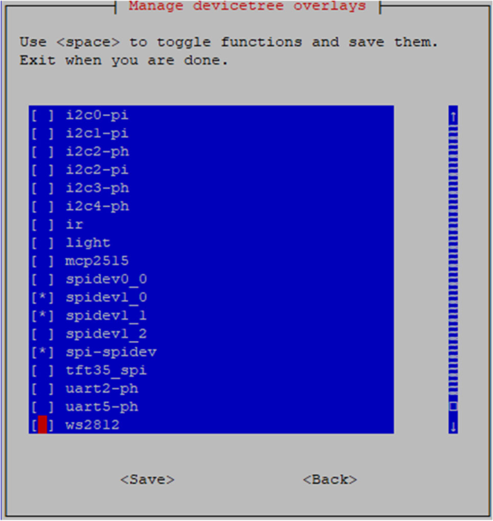
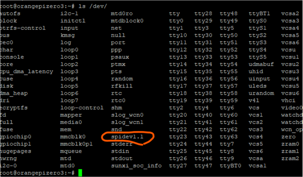
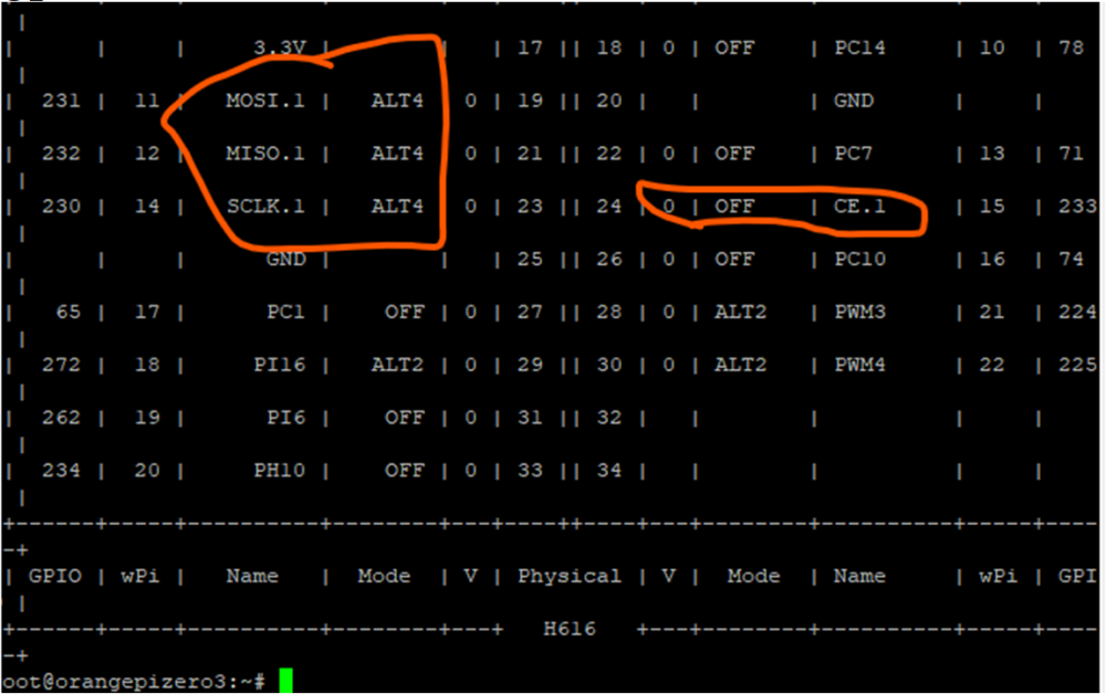
I managed to get the SPI to work. It is tested with the Minimal/IOT images with Armbian Linux v6.6 from the build date of end of January. I tried to copy the .dtbo files ( from above) to the following location: -/boot/dtb-6.6.72-current-sunxi64/allwinner/overlay The details can be found in the guide made by adif. 1. ls /dev > there is no spi 2. go to armbian-config What is spi* in orange pi zero3 ls /dev gpio readall 4. copy the .dtbo files ( from forum) to the following location -/boot/dtb-6.6.72-current-sunxi64/allwinner/overlay reboot gpio readall


-

Banana Pi M2U, can't fully boot
Christopher Johnson replied to Christopher Johnson's topic in Allwinner sunxi
Thank you @going I made the changes to the build as you suggested. No change. I modified the ftdfile to remove the serial@1c28c00. This changed the behavior, worsening it. I attempted to make an overlay to remove the serial port. That failed. I modified the ftdfile to remove the Bluetooth portion of the dtb. The results follow. I did read the examples on how to make an overlay. I need to spend more time figuring out overlays. Unless you have another suggestion, I'm going to get different hardware. I'm looking for a low cost, Arabian supported board with Ethernet and UART that can support PPS and supply 3.3v to my GPS board. I am avoiding wireless and USB solutions. U-Boot 2024.01-armbian-2024.01-S866c-P1dc6-Ha5c2-Ve536-Bb703-R448a (Feb 02 2025y CPU: Allwinner R40 (SUN8I 1701) Model: Banana Pi BPI-M2-Ultra DRAM: 2 GiB sunxi-pinctrl pinctrl@1c20800: pinctrl_select_state_full: pinctrl_config_one: e8 Core: 66 devices, 23 uclasses, devicetree: separate WDT: Not starting watchdog@1c20c90 MMC: gpio_sunxi pinctrl@1c20800: pinctrl_select_state_full: pinctrl_config_on8 mmc@1c0f000: 0, mmc@1c10000: 2, mmc@1c11000: 1 Loading Environment from FAT... Unable to use mmc 0:1... In: serial@1c28000 Out: serial@1c28000 Err: serial@1c28000 Net: eth0: ethernet@1c50000 starting USB... Bus usb@1c19000: Port not available. Bus usb@1c19400: Port not available. Bus usb@1c1c000: Port not available. Bus usb@1c1c400: Port not available. Hit any key to stop autoboot: 0 switch to partitions #0, OK mmc0 is current device Scanning mmc 0:1... Found U-Boot script /boot/boot.scr 5475 bytes read in 2 ms (2.6 MiB/s) ## Executing script at 43100000 U-boot loaded from SD 213 bytes read in 2 ms (103.5 KiB/s) Load fdt: /boot/dtb/bpi-m2u.dtb 11817555 bytes read in 489 ms (23 MiB/s) 11062840 bytes read in 459 ms (23 MiB/s) Found mainline kernel configuration 38513 bytes read in 4 ms (9.2 MiB/s) Working FDT set to 43000000 Kernel image @ 0x42000000 [ 0x000000 - 0xa8ce38 ] ## Loading init Ramdisk from Legacy Image at 43400000 ... Image Name: uInitrd Image Type: ARM Linux RAMDisk Image (gzip compressed) Data Size: 11817491 Bytes = 11.3 MiB Load Address: 00000000 Entry Point: 00000000 Verifying Checksum ... OK ## Flattened Device Tree blob at 43000000 Booting using the fdt blob at 0x43000000 Working FDT set to 43000000 Loading Ramdisk to 494ba000, end 49fff213 ... OK Loading Device Tree to 49448000, end 494b9fff ... OK Working FDT set to 49448000 Starting kernel ... [ 0.000000] Booting Linux on physical CPU 0x0 [ 0.000000] Linux version 6.12.9-edge-sunxi (build@armbian) (arm-linux-gnuea5 [ 0.000000] CPU: ARMv7 Processor [410fc075] revision 5 (ARMv7), cr=50c5387d [ 0.000000] CPU: div instructions available: patching division code [ 0.000000] CPU: PIPT / VIPT nonaliasing data cache, VIPT aliasing instructie [ 0.000000] OF: fdt: Machine model: Banana Pi BPI-M2-Ultra [ 0.000000] Memory policy: Data cache writealloc [ 0.000000] cma: Reserved 128 MiB at 0xb7800000 on node -1 [ 0.000000] Zone ranges: [ 0.000000] Normal [mem 0x0000000040000000-0x000000006fffffff] [ 0.000000] HighMem [mem 0x0000000070000000-0x00000000bfffffff] [ 0.000000] Movable zone start for each node [ 0.000000] Early memory node ranges [ 0.000000] node 0: [mem 0x0000000040000000-0x00000000bfffffff] [ 0.000000] Initmem setup node 0 [mem 0x0000000040000000-0x00000000bfffffff] [ 0.000000] psci: probing for conduit method from DT. [ 0.000000] psci: Using PSCI v0.1 Function IDs from DT [ 0.000000] percpu: Embedded 19 pages/cpu s48588 r8192 d21044 u77824 [ 0.000000] pcpu-alloc: s48588 r8192 d21044 u77824 alloc=19*4096 [ 0.000000] pcpu-alloc: [0] 0 [0] 1 [0] 2 [0] 3 [ 0.000000] Kernel command line: root=UUID=752691d3-0190-4fbe-8bdc-1df150890y [ 0.000000] Unknown kernel command line parameters "splash=verbose ubootpart. [ 0.000000] Dentry cache hash table entries: 131072 (order: 7, 524288 bytes,) [ 0.000000] Inode-cache hash table entries: 65536 (order: 6, 262144 bytes, l) [ 0.000000] Built 1 zonelists, mobility grouping on. Total pages: 524288 [ 0.000000] mem auto-init: stack:off, heap alloc:on, heap free:off [ 0.000000] SLUB: HWalign=64, Order=0-3, MinObjects=0, CPUs=4, Nodes=1 [ 0.000000] allocated 2097152 bytes of page_ext [ 0.000000] ftrace: allocating 47374 entries in 139 pages [ 0.000000] ftrace: allocated 139 pages with 4 groups [ 0.000000] rcu: Hierarchical RCU implementation. [ 0.000000] rcu: RCU restricting CPUs from NR_CPUS=8 to nr_cpu_ids=4. [ 0.000000] Rude variant of Tasks RCU enabled. [ 0.000000] Tracing variant of Tasks RCU enabled. [ 0.000000] rcu: RCU calculated value of scheduler-enlistment delay is 25 ji. [ 0.000000] rcu: Adjusting geometry for rcu_fanout_leaf=16, nr_cpu_ids=4 [ 0.000000] RCU Tasks Rude: Setting shift to 2 and lim to 1 rcu_task_cb_adju. [ 0.000000] RCU Tasks Trace: Setting shift to 2 and lim to 1 rcu_task_cb_adj. [ 0.000000] NR_IRQS: 16, nr_irqs: 16, preallocated irqs: 16 [ 0.000000] GIC: Using split EOI/Deactivate mode [ 0.000000] rcu: srcu_init: Setting srcu_struct sizes based on contention. [ 0.000000] clocksource: timer: mask: 0xffffffff max_cycles: 0xffffffff, maxs [ 0.000000] arch_timer: cp15 timer(s) running at 24.00MHz (phys). [ 0.000000] clocksource: arch_sys_counter: mask: 0xffffffffffffff max_cycless [ 0.000002] sched_clock: 56 bits at 24MHz, resolution 41ns, wraps every 4398s [ 0.000016] Switching to timer-based delay loop, resolution 41ns [ 0.000501] Console: colour dummy device 80x30 [ 0.000521] printk: legacy console [tty1] enabled [ 0.001207] Calibrating delay loop (skipped), value calculated using timer f) [ 0.001245] CPU: Testing write buffer coherency: ok [ 0.001321] pid_max: default: 32768 minimum: 301 [ 0.008978] LSM: initializing lsm=capability,yama,apparmor [ 0.011739] Yama: becoming mindful. [ 0.012103] AppArmor: AppArmor initialized [ 0.013357] Mount-cache hash table entries: 2048 (order: 1, 8192 bytes, line) [ 0.013398] Mountpoint-cache hash table entries: 2048 (order: 1, 8192 bytes,) [ 0.018342] CPU0: thread -1, cpu 0, socket 0, mpidr 80000000 [ 0.036476] Setting up static identity map for 0x40100000 - 0x40100054 [ 0.040147] rcu: Hierarchical SRCU implementation. [ 0.040175] rcu: Max phase no-delay instances is 1000. [ 0.040577] Timer migration: 1 hierarchy levels; 8 children per group; 1 crol [ 0.048227] smp: Bringing up secondary CPUs ... [ 0.070555] CPU1: thread -1, cpu 1, socket 0, mpidr 80000001 [ 0.088679] CPU2: thread -1, cpu 2, socket 0, mpidr 80000002 [ 0.110806] CPU3: thread -1, cpu 3, socket 0, mpidr 80000003 [ 0.110958] smp: Brought up 1 node, 4 CPUs [ 0.111034] SMP: Total of 4 processors activated (192.00 BogoMIPS). [ 0.111057] CPU: All CPU(s) started in HYP mode. [ 0.111074] CPU: Virtualization extensions available. [ 0.111337] Memory: 1905260K/2097152K available (10240K kernel code, 1727K r) [ 0.112816] devtmpfs: initialized [ 0.122924] VFP support v0.3: implementor 41 architecture 2 part 30 variant 5 [ 0.123226] clocksource: jiffies: mask: 0xffffffff max_cycles: 0xffffffff, ms [ 0.123300] futex hash table entries: 1024 (order: 4, 65536 bytes, linear) [ 0.132082] pinctrl core: initialized pinctrl subsystem [ 0.135294] NET: Registered PF_NETLINK/PF_ROUTE protocol family [ 0.142117] DMA: preallocated 256 KiB pool for atomic coherent allocations [ 0.142920] audit: initializing netlink subsys (disabled) [ 0.143331] audit: type=2000 audit(0.124:1): state=initialized audit_enabled1 [ 0.143823] thermal_sys: Registered thermal governor 'fair_share' [ 0.143836] thermal_sys: Registered thermal governor 'bang_bang' [ 0.143860] thermal_sys: Registered thermal governor 'step_wise' [ 0.143949] cpuidle: using governor ladder [ 0.144020] cpuidle: using governor menu [ 0.144607] hw-breakpoint: found 5 (+1 reserved) breakpoint and 4 watchpoint. [ 0.144641] hw-breakpoint: maximum watchpoint size is 8 bytes. [ 0.151065] /soc/mixer@1100000: Fixed dependency cycle(s) with /soc/tcon-top0 [ 0.151170] /soc/mixer@1200000: Fixed dependency cycle(s) with /soc/tcon-top0 [ 0.151657] /soc/tcon-top@1c70000: Fixed dependency cycle(s) with /soc/hdmi@0 [ 0.151703] /soc/tcon-top@1c70000: Fixed dependency cycle(s) with /soc/mixer0 [ 0.151745] /soc/tcon-top@1c70000: Fixed dependency cycle(s) with /soc/lcd-c0 [ 0.151788] /soc/tcon-top@1c70000: Fixed dependency cycle(s) with /soc/mixer0 [ 0.151882] /soc/lcd-controller@1c73000: Fixed dependency cycle(s) with /soc0 [ 0.151935] /soc/interrupt-controller@1c81000: Fixed dependency cycle(s) wit0 [ 0.152001] /soc/hdmi@1ee0000: Fixed dependency cycle(s) with /soc/tcon-top@0 [ 0.152413] /soc/mixer@1100000: Fixed dependency cycle(s) with /soc/tcon-top0 [ 0.152760] /soc/mixer@1200000: Fixed dependency cycle(s) with /soc/tcon-top0 [ 0.157019] /soc/pinctrl@1c20800: Fixed dependency cycle(s) with /soc/pinctrn [ 0.159506] /soc/i2c@1c2ac00: Fixed dependency cycle(s) with /soc/pinctrl@1cs [ 0.160672] /soc/mixer@1200000: Fixed dependency cycle(s) with /soc/tcon-top0 [ 0.160786] /soc/mixer@1100000: Fixed dependency cycle(s) with /soc/tcon-top0 [ 0.160887] /soc/tcon-top@1c70000: Fixed dependency cycle(s) with /soc/hdmi@0 [ 0.160927] /soc/tcon-top@1c70000: Fixed dependency cycle(s) with /soc/mixer0 [ 0.161071] /soc/tcon-top@1c70000: Fixed dependency cycle(s) with /soc/lcd-c0 [ 0.161115] /soc/tcon-top@1c70000: Fixed dependency cycle(s) with /soc/mixer0 [ 0.161451] /soc/tcon-top@1c70000: Fixed dependency cycle(s) with /soc/lcd-c0 [ 0.161568] /soc/lcd-controller@1c73000: Fixed dependency cycle(s) with /soc0 [ 0.161942] /soc/tcon-top@1c70000: Fixed dependency cycle(s) with /soc/hdmi@0 [ 0.162079] /soc/hdmi@1ee0000: Fixed dependency cycle(s) with /soc/tcon-top@0 [ 0.163007] /soc/hdmi@1ee0000: Fixed dependency cycle(s) with /connector [ 0.163122] /connector: Fixed dependency cycle(s) with /soc/hdmi@1ee0000 [ 0.172182] cryptd: max_cpu_qlen set to 1000 [ 0.238957] raid6: neonx8 gen() 662 MB/s [ 0.307105] raid6: neonx4 gen() 903 MB/s [ 0.375210] raid6: neonx2 gen() 911 MB/s [ 0.443332] raid6: neonx1 gen() 746 MB/s [ 0.511476] raid6: int32x8 gen() 283 MB/s [ 0.579498] raid6: int32x4 gen() 315 MB/s [ 0.647624] raid6: int32x2 gen() 410 MB/s [ 0.715720] raid6: int32x1 gen() 368 MB/s [ 0.715744] raid6: using algorithm neonx2 gen() 911 MB/s [ 0.783779] raid6: .... xor() 675 MB/s, rmw enabled [ 0.783801] raid6: using neon recovery algorithm [ 0.785579] iommu: Default domain type: Translated [ 0.785613] iommu: DMA domain TLB invalidation policy: strict mode [ 0.786344] SCSI subsystem initialized [ 0.786602] usbcore: registered new interface driver usbfs [ 0.786661] usbcore: registered new interface driver hub [ 0.786722] usbcore: registered new device driver usb [ 0.786955] pps_core: LinuxPPS API ver. 1 registered [ 0.786977] pps_core: Software ver. 5.3.6 - Copyright 2005-2007 Rodolfo Giom> [ 0.787017] PTP clock support registered [ 0.787686] Advanced Linux Sound Architecture Driver Initialized. [ 0.788927] NetLabel: Initializing [ 0.788959] NetLabel: domain hash size = 128 [ 0.788976] NetLabel: protocols = UNLABELED CIPSOv4 CALIPSO [ 0.789089] NetLabel: unlabeled traffic allowed by default [ 0.789991] clocksource: Switched to clocksource arch_sys_counter [ 0.800668] VFS: Disk quotas dquot_6.6.0 [ 0.800997] VFS: Dquot-cache hash table entries: 1024 (order 0, 4096 bytes) [ 0.801704] AppArmor: AppArmor Filesystem Enabled [ 0.814121] NET: Registered PF_INET protocol family [ 0.814411] IP idents hash table entries: 16384 (order: 5, 131072 bytes, lin) [ 0.890594] tcp_listen_portaddr_hash hash table entries: 512 (order: 0, 4096) [ 0.890776] Table-perturb hash table entries: 65536 (order: 6, 262144 bytes,) [ 0.890828] TCP established hash table entries: 8192 (order: 3, 32768 bytes,) [ 0.891004] TCP bind hash table entries: 8192 (order: 5, 131072 bytes, linea) [ 0.891324] TCP: Hash tables configured (established 8192 bind 8192) [ 0.891584] UDP hash table entries: 512 (order: 2, 16384 bytes, linear) [ 0.891697] UDP-Lite hash table entries: 512 (order: 2, 16384 bytes, linear) [ 0.892334] NET: Registered PF_UNIX/PF_LOCAL protocol family [ 0.892912] Trying to unpack rootfs image as initramfs... [ 0.895899] Initialise system trusted keyrings [ 0.896115] Key type blacklist registered [ 0.896501] workingset: timestamp_bits=14 max_order=19 bucket_order=5 [ 0.896600] zbud: loaded [ 0.907482] squashfs: version 4.0 (2009/01/31) Phillip Lougher [ 0.916132] fuse: init (API version 7.41) [ 0.928468] integrity: Platform Keyring initialized [ 1.159954] xor: measuring software checksum speed [ 1.162621] arm4regs : 1264 MB/sec [ 1.166484] 8regs : 858 MB/sec [ 1.170433] 32regs : 839 MB/sec [ 1.172931] neon : 1329 MB/sec [ 1.172956] xor: using function: neon (1329 MB/sec) [ 1.172999] Key type asymmetric registered [ 1.173031] Asymmetric key parser 'x509' registered [ 1.173537] bounce: pool size: 64 pages [ 1.174143] Block layer SCSI generic (bsg) driver version 0.4 loaded (major ) [ 1.174594] io scheduler mq-deadline registered [ 1.174633] io scheduler kyber registered [ 1.175121] io scheduler bfq registered [ 1.183263] ledtrig-cpu: registered to indicate activity on CPUs [ 1.196396] Serial: 8250/16550 driver, 8 ports, IRQ sharing disabled [ 1.212301] brd: module loaded [ 1.219050] loop: module loaded [ 1.224109] usbcore: registered new interface driver usb-storage [ 1.225638] sun6i-rtc 1c20400.rtc: registered as rtc0 [ 1.225716] sun6i-rtc 1c20400.rtc: setting system clock to 1970-01-01T00:00:) [ 1.226426] i2c_dev: i2c /dev entries driver [ 1.228241] sunxi-wdt 1c20c90.watchdog: Watchdog enabled (timeout=16 sec, no) [ 1.229896] sun8i-ce 1c15000.crypto: Set mod clock to 300000000 (300 Mhz) fr) [ 1.230515] sun8i-ce 1c15000.crypto: will run requests pump with realtime pry [ 1.232632] sun8i-ce 1c15000.crypto: will run requests pump with realtime pry [ 1.234080] sun8i-ce 1c15000.crypto: will run requests pump with realtime pry [ 1.235485] sun8i-ce 1c15000.crypto: will run requests pump with realtime pry [ 1.236724] sun8i-ce 1c15000.crypto: Register cbc(aes) [ 1.236797] sun8i-ce 1c15000.crypto: Register ecb(aes) [ 1.236827] sun8i-ce 1c15000.crypto: Register cbc(des3_ede) [ 1.236856] sun8i-ce 1c15000.crypto: Register ecb(des3_ede) [ 1.236885] sun8i-ce 1c15000.crypto: Register md5 [ 1.236914] sun8i-ce 1c15000.crypto: Register sha1 [ 1.236942] sun8i-ce 1c15000.crypto: Register sha224 [ 1.236971] sun8i-ce 1c15000.crypto: Register sha256 [ 1.237001] sun8i-ce 1c15000.crypto: DEBUG: Algo of sha384 not supported [ 1.237024] sun8i-ce 1c15000.crypto: DEBUG: Algo of sha512 not supported [ 1.237045] sun8i-ce 1c15000.crypto: Register stdrng [ 1.237098] sun8i-ce 1c15000.crypto: TRNG not supported [ 1.237120] sun8i-ce 1c15000.crypto: CryptoEngine Die ID 0 [ 1.238016] hid: raw HID events driver (C) Jiri Kosina [ 1.238195] usbcore: registered new interface driver usbhid [ 1.238220] usbhid: USB HID core driver [ 1.239841] hw perfevents: enabled with armv7_cortex_a7 PMU driver, 5 (80000e [ 1.251708] Initializing XFRM netlink socket [ 1.252963] NET: Registered PF_INET6 protocol family [ 1.693243] Freeing initrd memory: 11544K [ 1.752163] Segment Routing with IPv6 [ 1.752324] In-situ OAM (IOAM) with IPv6 [ 1.752513] NET: Registered PF_PACKET protocol family [ 1.752551] NET: Registered PF_KEY protocol family [ 1.752618] bridge: filtering via arp/ip/ip6tables is no longer available by. [ 1.752873] 8021q: 802.1Q VLAN Support v1.8 [ 1.752990] Key type dns_resolver registered [ 1.753558] Registering SWP/SWPB emulation handler [ 1.764076] registered taskstats version 1 [ 1.764468] Loading compiled-in X.509 certificates [ 1.782712] zswap: loaded using pool zstd/z3fold [ 1.783944] Key type .fscrypt registered [ 1.783981] Key type fscrypt-provisioning registered [ 1.795509] Btrfs loaded, zoned=no, fsverity=yes [ 1.936530] Key type encrypted registered [ 1.936596] AppArmor: AppArmor sha256 policy hashing enabled [ 1.953509] sun4i-pinctrl 1c20800.pinctrl: supply vcc-pi not found, using dur [ 1.953908] gpio gpiochip0: Static allocation of GPIO base is deprecated, us. [ 1.956014] sun4i-pinctrl 1c20800.pinctrl: initialized sunXi PIO driver [ 1.956965] sun4i-pinctrl 1c20800.pinctrl: supply vcc-ph not found, using dur [ 1.957842] sun4i-pinctrl 1c20800.pinctrl: supply vcc-pb not found, using dur [ 1.958667] printk: legacy console [ttyS0] disabled [ 1.959152] 1c28000.serial: ttyS0 at MMIO 0x1c28000 (irq = 74, base_baud = 1A [ 1.959246] printk: legacy console [ttyS0] enabled [ 3.387016] dw-apb-uart 1c28c00.serial: Error applying setting, reverse think [ 3.425469] sun4i-drm display-engine: bound 1100000.mixer (ops 0xc0bb7364) [ 3.434315] sun4i-drm display-engine: bound 1200000.mixer (ops 0xc0bb7364) [ 3.441709] sun4i-drm display-engine: bound 1c70000.tcon-top (ops 0xc0bbb960) [ 3.449394] sun4i-drm display-engine: bound 1c73000.lcd-controller (ops 0xc0) [ 3.457179] sun8i-dw-hdmi 1ee0000.hdmi: supply hvcc not found, using dummy rr [ 3.466065] sun8i-dw-hdmi 1ee0000.hdmi: Detected HDMI TX controller v1.32a w) [ 3.476413] sun8i-dw-hdmi 1ee0000.hdmi: registered DesignWare HDMI I2C bus dr [ 3.484377] sun4i-drm display-engine: bound 1ee0000.hdmi (ops 0xc0bb6904) [ 3.492029] [drm] Initialized sun4i-drm 1.0.0 for display-engine on minor 0 [ 3.499136] sun4i-drm display-engine: [drm] Cannot find any crtc or sizes [ 3.509735] sun4i-drm display-engine: [drm] Cannot find any crtc or sizes [ 3.510351] axp20x-i2c 1-0034: AXP20x variant AXP221 found [ 3.538485] input: axp20x-pek as /devices/platform/soc/1c2ac00.i2c/i2c-1/1-00 [ 3.548713] axp20x-i2c 1-0034: AXP20X driver loaded [ 3.557161] sunxi-mmc 1c10000.mmc: Error applying setting, reverse things bak [ 3.557466] dw-apb-uart 1c28c00.serial: Error applying setting, reverse think [ 3.563337] vcc-wifi-io: Bringing 700000uV into 1800000-1800000uV [ 3.564462] vcc-wifi: Bringing 700000uV into 3300000-3300000uV [ 3.565499] dwmac-sun8i 1c50000.ethernet: IRQ eth_wake_irq not found [ 3.573724] vcc-wifi-2: Bringing 700000uV into 3300000-3300000uV [ 3.578352] dwmac-sun8i 1c50000.ethernet: IRQ eth_lpi not found [ 3.578364] dwmac-sun8i 1c50000.ethernet: IRQ sfty not found [ 3.608450] dwmac-sun8i 1c50000.ethernet: supply phy-io not found, using dumr [ 3.616795] dwmac-sun8i 1c50000.ethernet: PTP uses main clock [ 3.622605] dwmac-sun8i 1c50000.ethernet: Current syscon value is not the de) [ 3.631735] sunxi-mmc 1c0f000.mmc: Got CD GPIO [ 3.631803] dwmac-sun8i 1c50000.ethernet: No HW DMA feature register supportd [ 3.643537] dwmac-sun8i 1c50000.ethernet: RX Checksum Offload Engine supportd [ 3.650800] dwmac-sun8i 1c50000.ethernet: COE Type 2 [ 3.655782] dwmac-sun8i 1c50000.ethernet: TX Checksum insertion supported [ 3.662409] sunxi-mmc 1c0f000.mmc: initialized, max. request size: 16384 KB,e [ 3.662591] dwmac-sun8i 1c50000.ethernet: Normal descriptors [ 3.677240] dwmac-sun8i 1c50000.ethernet: Chain mode enabled [ 3.705995] sunxi-mmc 1c11000.mmc: initialized, max. request size: 2048 KB, e [ 3.724670] mmc0: host does not support reading read-only switch, assuming we [ 3.729186] 1c28c00.serial: ttyS1 at MMIO 0x1c28c00 (irq = 108, base_baud = A [ 3.741811] mmc0: new high U-Boot SPL 2024.01-armbian-2024.01-S866c-P1dc6-Ha5c2-Ve536-Bb703-R448a (Feb 02 ) Again, thank you for your help. -
Banana Pi M2U, can't fully boot
Christopher Johnson replied to Christopher Johnson's topic in Allwinner sunxi
U-Boot SPL 2024.01-armbian-2024.01-S866c-P7738-Ha5c2-Ve536-Bb703-R448a (Jan 28 ) DRAM: 2048 MiB Trying to boot from MMC1 ns16550_serial serial@1c28000: pinctrl_select_state_full: uclass_get_device_by_9 U-Boot 2024.01-armbian-2024.01-S866c-P7738-Ha5c2-Ve536-Bb703-R448a (Jan 28 2025y CPU: Allwinner R40 (SUN8I 1701) Model: Banana Pi BPI-M2-Ultra DRAM: 2 GiB sunxi-pinctrl pinctrl@1c20800: pinctrl_select_state_full: pinctrl_config_one: e8 Core: 66 devices, 23 uclasses, devicetree: separate WDT: Not starting watchdog@1c20c90 MMC: gpio_sunxi pinctrl@1c20800: pinctrl_select_state_full: pinctrl_config_on8 mmc@1c0f000: 0, mmc@1c10000: 2, mmc@1c11000: 1 Loading Environment from FAT... Unable to use mmc 0:1... In: serial@1c28000 Out: serial@1c28000 Err: serial@1c28000 Net: eth0: ethernet@1c50000 starting USB... Bus usb@1c19000: Port not available. Bus usb@1c19400: Port not available. Bus usb@1c1c000: Port not available. Bus usb@1c1c400: Port not available. Autoboot in 1 seconds, press <Space> to stop switch to partitions #0, OK mmc0 is current device Scanning mmc 0:1... Found U-Boot script /boot/boot.scr 5475 bytes read in 3 ms (1.7 MiB/s) ## Executing script at 43100000 U-boot loaded from SD 154 bytes read in 1 ms (150.4 KiB/s) Load fdt: /boot/dtb/sun8i-r40-bananapi-m2-ultra.dtb 18494741 bytes read in 766 ms (23 MiB/s) 11192320 bytes read in 463 ms (23.1 MiB/s) Found mainline kernel configuration 38775 bytes read in 6 ms (6.2 MiB/s) Working FDT set to 43000000 Kernel image @ 0x42000000 [ 0x000000 - 0xaac800 ] ## Loading init Ramdisk from Legacy Image at 43400000 ... Image Name: uInitrd Image Type: ARM Linux RAMDisk Image (gzip compressed) Data Size: 18494677 Bytes = 17.6 MiB Load Address: 00000000 Entry Point: 00000000 Verifying Checksum ... OK ## Flattened Device Tree blob at 43000000 Booting using the fdt blob at 0x43000000 Working FDT set to 43000000 Loading Ramdisk to 48e5c000, end 49fff4d5 ... OK Loading Device Tree to 48dea000, end 48e5bfff ... OK Working FDT set to 48dea000 Starting kernel ... [ 0.000000] Booting Linux on physical CPU 0x0 [ 0.000000] Linux version 6.12.9-edge-sunxi (build@armbian) (arm-linux-gnuea5 [ 0.000000] CPU: ARMv7 Processor [410fc075] revision 5 (ARMv7), cr=50c5387d [ 0.000000] CPU: div instructions available: patching division code [ 0.000000] CPU: PIPT / VIPT nonaliasing data cache, VIPT aliasing instructie [ 0.000000] OF: fdt: Machine model: Banana Pi BPI-M2-Ultra [ 0.000000] Memory policy: Data cache writealloc [ 0.000000] cma: Reserved 128 MiB at 0xb7800000 on node -1 [ 0.000000] Zone ranges: [ 0.000000] Normal [mem 0x0000000040000000-0x000000006fffffff] [ 0.000000] HighMem [mem 0x0000000070000000-0x00000000bfffffff] [ 0.000000] Movable zone start for each node [ 0.000000] Early memory node ranges [ 0.000000] node 0: [mem 0x0000000040000000-0x00000000bfffffff] [ 0.000000] Initmem setup node 0 [mem 0x0000000040000000-0x00000000bfffffff] [ 0.000000] psci: probing for conduit method from DT. [ 0.000000] psci: Using PSCI v0.1 Function IDs from DT [ 0.000000] percpu: Embedded 19 pages/cpu s48588 r8192 d21044 u77824 [ 0.000000] pcpu-alloc: s48588 r8192 d21044 u77824 alloc=19*4096 [ 0.000000] pcpu-alloc: [0] 0 [0] 1 [0] 2 [0] 3 [ 0.000000] Kernel command line: root=UUID=0e044996-0309-4020-a339-c57ef4c26y [ 0.000000] Unknown kernel command line parameters "splash=verbose ubootpart. [ 0.000000] Dentry cache hash table entries: 131072 (order: 7, 524288 bytes,) [ 0.000000] Inode-cache hash table entries: 65536 (order: 6, 262144 bytes, l) [ 0.000000] Built 1 zonelists, mobility grouping on. Total pages: 524288 [ 0.000000] mem auto-init: stack:off, heap alloc:on, heap free:off [ 0.000000] SLUB: HWalign=64, Order=0-3, MinObjects=0, CPUs=4, Nodes=1 [ 0.000000] allocated 2097152 bytes of page_ext [ 0.000000] ftrace: allocating 47896 entries in 141 pages [ 0.000000] ftrace: allocated 141 pages with 4 groups [ 0.000000] rcu: Hierarchical RCU implementation. [ 0.000000] rcu: RCU restricting CPUs from NR_CPUS=8 to nr_cpu_ids=4. [ 0.000000] Rude variant of Tasks RCU enabled. [ 0.000000] Tracing variant of Tasks RCU enabled. [ 0.000000] rcu: RCU calculated value of scheduler-enlistment delay is 25 ji. [ 0.000000] rcu: Adjusting geometry for rcu_fanout_leaf=16, nr_cpu_ids=4 [ 0.000000] RCU Tasks Rude: Setting shift to 2 and lim to 1 rcu_task_cb_adju. [ 0.000000] RCU Tasks Trace: Setting shift to 2 and lim to 1 rcu_task_cb_adj. [ 0.000000] NR_IRQS: 16, nr_irqs: 16, preallocated irqs: 16 [ 0.000000] GIC: Using split EOI/Deactivate mode [ 0.000000] rcu: srcu_init: Setting srcu_struct sizes based on contention. [ 0.000000] clocksource: timer: mask: 0xffffffff max_cycles: 0xffffffff, maxs [ 0.000000] arch_timer: cp15 timer(s) running at 24.00MHz (phys). [ 0.000000] clocksource: arch_sys_counter: mask: 0xffffffffffffff max_cycless [ 0.000002] sched_clock: 56 bits at 24MHz, resolution 41ns, wraps every 4398s [ 0.000016] Switching to timer-based delay loop, resolution 41ns [ 0.000510] Console: colour dummy device 80x30 [ 0.000533] printk: legacy console [tty1] enabled [ 0.001225] Calibrating delay loop (skipped), value calculated using timer f) [ 0.001263] CPU: Testing write buffer coherency: ok [ 0.001344] pid_max: default: 32768 minimum: 301 [ 0.009055] LSM: initializing lsm=capability,yama,apparmor [ 0.011739] Yama: becoming mindful. [ 0.012116] AppArmor: AppArmor initialized [ 0.013382] Mount-cache hash table entries: 2048 (order: 1, 8192 bytes, line) [ 0.013421] Mountpoint-cache hash table entries: 2048 (order: 1, 8192 bytes,) [ 0.018431] CPU0: thread -1, cpu 0, socket 0, mpidr 80000000 [ 0.036495] Setting up static identity map for 0x40100000 - 0x40100054 [ 0.040160] rcu: Hierarchical SRCU implementation. [ 0.040187] rcu: Max phase no-delay instances is 1000. [ 0.040604] Timer migration: 1 hierarchy levels; 8 children per group; 1 crol [ 0.048246] smp: Bringing up secondary CPUs ... [ 0.070582] CPU1: thread -1, cpu 1, socket 0, mpidr 80000001 [ 0.092740] CPU2: thread -1, cpu 2, socket 0, mpidr 80000002 [ 0.110851] CPU3: thread -1, cpu 3, socket 0, mpidr 80000003 [ 0.111012] smp: Brought up 1 node, 4 CPUs [ 0.111088] SMP: Total of 4 processors activated (192.00 BogoMIPS). [ 0.111114] CPU: All CPU(s) started in HYP mode. [ 0.111132] CPU: Virtualization extensions available. [ 0.111402] Memory: 1897660K/2097152K available (11264K kernel code, 1757K r) [ 0.112905] devtmpfs: initialized [ 0.123299] VFP support v0.3: implementor 41 architecture 2 part 30 variant 5 [ 0.123607] clocksource: jiffies: mask: 0xffffffff max_cycles: 0xffffffff, ms [ 0.123682] futex hash table entries: 1024 (order: 4, 65536 bytes, linear) [ 0.132563] pinctrl core: initialized pinctrl subsystem [ 0.135807] NET: Registered PF_NETLINK/PF_ROUTE protocol family [ 0.142753] DMA: preallocated 256 KiB pool for atomic coherent allocations [ 0.143576] audit: initializing netlink subsys (disabled) [ 0.144004] audit: type=2000 audit(0.124:1): state=initialized audit_enabled1 [ 0.144489] thermal_sys: Registered thermal governor 'fair_share' [ 0.144500] thermal_sys: Registered thermal governor 'bang_bang' [ 0.144524] thermal_sys: Registered thermal governor 'step_wise' [ 0.144620] cpuidle: using governor ladder [ 0.144687] cpuidle: using governor menu [ 0.145295] hw-breakpoint: found 5 (+1 reserved) breakpoint and 4 watchpoint. [ 0.145329] hw-breakpoint: maximum watchpoint size is 8 bytes. [ 0.151854] /soc/mixer@1100000: Fixed dependency cycle(s) with /soc/tcon-top0 [ 0.151957] /soc/mixer@1200000: Fixed dependency cycle(s) with /soc/tcon-top0 [ 0.152483] /soc/tcon-top@1c70000: Fixed dependency cycle(s) with /soc/hdmi@0 [ 0.152529] /soc/tcon-top@1c70000: Fixed dependency cycle(s) with /soc/mixer0 [ 0.152571] /soc/tcon-top@1c70000: Fixed dependency cycle(s) with /soc/lcd-c0 [ 0.152615] /soc/tcon-top@1c70000: Fixed dependency cycle(s) with /soc/mixer0 [ 0.152708] /soc/lcd-controller@1c73000: Fixed dependency cycle(s) with /soc0 [ 0.152761] /soc/interrupt-controller@1c81000: Fixed dependency cycle(s) wit0 [ 0.152827] /soc/hdmi@1ee0000: Fixed dependency cycle(s) with /soc/tcon-top@0 [ 0.153236] /soc/mixer@1100000: Fixed dependency cycle(s) with /soc/tcon-top0 [ 0.153582] /soc/mixer@1200000: Fixed dependency cycle(s) with /soc/tcon-top0 [ 0.157858] /soc/pinctrl@1c20800: Fixed dependency cycle(s) with /soc/pinctrn [ 0.160496] /soc/i2c@1c2ac00: Fixed dependency cycle(s) with /soc/pinctrl@1cs [ 0.161617] /soc/mixer@1200000: Fixed dependency cycle(s) with /soc/tcon-top0 [ 0.161754] /soc/mixer@1100000: Fixed dependency cycle(s) with /soc/tcon-top0 [ 0.161858] /soc/tcon-top@1c70000: Fixed dependency cycle(s) with /soc/hdmi@0 [ 0.161898] /soc/tcon-top@1c70000: Fixed dependency cycle(s) with /soc/mixer0 [ 0.161993] /soc/tcon-top@1c70000: Fixed dependency cycle(s) with /soc/lcd-c0 [ 0.162034] /soc/tcon-top@1c70000: Fixed dependency cycle(s) with /soc/mixer0 [ 0.162396] /soc/tcon-top@1c70000: Fixed dependency cycle(s) with /soc/lcd-c0 [ 0.162529] /soc/lcd-controller@1c73000: Fixed dependency cycle(s) with /soc0 [ 0.162917] /soc/tcon-top@1c70000: Fixed dependency cycle(s) with /soc/hdmi@0 [ 0.163032] /soc/hdmi@1ee0000: Fixed dependency cycle(s) with /soc/tcon-top@0 [ 0.164001] /soc/hdmi@1ee0000: Fixed dependency cycle(s) with /connector [ 0.164115] /connector: Fixed dependency cycle(s) with /soc/hdmi@1ee0000 [ 0.173721] cryptd: max_cpu_qlen set to 1000 [ 0.243035] raid6: neonx8 gen() 658 MB/s [ 0.311179] raid6: neonx4 gen() 904 MB/s [ 0.379300] raid6: neonx2 gen() 911 MB/s [ 0.447393] raid6: neonx1 gen() 746 MB/s [ 0.515563] raid6: int32x8 gen() 283 MB/s [ 0.583639] raid6: int32x4 gen() 315 MB/s [ 0.651716] raid6: int32x2 gen() 410 MB/s [ 0.719785] raid6: int32x1 gen() 368 MB/s [ 0.719808] raid6: using algorithm neonx2 gen() 911 MB/s [ 0.787881] raid6: .... xor() 675 MB/s, rmw enabled [ 0.787904] raid6: using neon recovery algorithm [ 0.789687] iommu: Default domain type: Translated [ 0.789722] iommu: DMA domain TLB invalidation policy: strict mode [ 0.790358] SCSI subsystem initialized [ 0.790731] libata version 3.00 loaded. [ 0.790952] usbcore: registered new interface driver usbfs [ 0.791051] usbcore: registered new interface driver hub [ 0.791111] usbcore: registered new device driver usb [ 0.791339] pps_core: LinuxPPS API ver. 1 registered [ 0.791364] pps_core: Software ver. 5.3.6 - Copyright 2005-2007 Rodolfo Giom> [ 0.791408] PTP clock support registered [ 0.791947] Advanced Linux Sound Architecture Driver Initialized. [ 0.793231] NetLabel: Initializing [ 0.793259] NetLabel: domain hash size = 128 [ 0.793276] NetLabel: protocols = UNLABELED CIPSOv4 CALIPSO [ 0.793418] NetLabel: unlabeled traffic allowed by default [ 0.794291] clocksource: Switched to clocksource arch_sys_counter [ 0.804284] VFS: Disk quotas dquot_6.6.0 [ 0.804623] VFS: Dquot-cache hash table entries: 1024 (order 0, 4096 bytes) [ 0.805410] AppArmor: AppArmor Filesystem Enabled [ 0.818610] NET: Registered PF_INET protocol family [ 0.818953] IP idents hash table entries: 16384 (order: 5, 131072 bytes, lin) [ 0.896809] tcp_listen_portaddr_hash hash table entries: 512 (order: 0, 4096) [ 0.896993] Table-perturb hash table entries: 65536 (order: 6, 262144 bytes,) [ 0.897054] TCP established hash table entries: 8192 (order: 3, 32768 bytes,) [ 0.897195] TCP bind hash table entries: 8192 (order: 5, 131072 bytes, linea) [ 0.897538] TCP: Hash tables configured (established 8192 bind 8192) [ 0.897706] UDP hash table entries: 512 (order: 2, 16384 bytes, linear) [ 0.897788] UDP-Lite hash table entries: 512 (order: 2, 16384 bytes, linear) [ 0.898467] NET: Registered PF_UNIX/PF_LOCAL protocol family [ 0.898923] Trying to unpack rootfs image as initramfs... [ 0.901966] Initialise system trusted keyrings [ 0.902087] Key type blacklist registered [ 0.902626] workingset: timestamp_bits=14 max_order=19 bucket_order=5 [ 0.902768] zbud: loaded [ 0.913665] squashfs: version 4.0 (2009/01/31) Phillip Lougher [ 0.922635] fuse: init (API version 7.41) [ 0.932248] integrity: Platform Keyring initialized [ 1.163161] xor: measuring software checksum speed [ 1.165776] arm4regs : 1286 MB/sec [ 1.169620] 8regs : 860 MB/sec [ 1.173576] 32regs : 837 MB/sec [ 1.176106] neon : 1315 MB/sec [ 1.176137] xor: using function: neon (1315 MB/sec) [ 1.176186] Key type asymmetric registered [ 1.176208] Asymmetric key parser 'x509' registered [ 1.176696] bounce: pool size: 64 pages [ 1.177206] Block layer SCSI generic (bsg) driver version 0.4 loaded (major ) [ 1.177802] io scheduler mq-deadline registered [ 1.177843] io scheduler kyber registered [ 1.178377] io scheduler bfq registered [ 1.188798] ledtrig-cpu: registered to indicate activity on CPUs [ 1.202060] Serial: 8250/16550 driver, 8 ports, IRQ sharing disabled [ 1.217946] brd: module loaded [ 1.224994] loop: module loaded [ 1.230626] usbcore: registered new interface driver usb-storage [ 1.232153] sun6i-rtc 1c20400.rtc: registered as rtc0 [ 1.232234] sun6i-rtc 1c20400.rtc: setting system clock to 1970-01-01T00:00:) [ 1.232887] i2c_dev: i2c /dev entries driver [ 1.234768] sunxi-wdt 1c20c90.watchdog: Watchdog enabled (timeout=16 sec, no) [ 1.236465] sun8i-ce 1c15000.crypto: Set mod clock to 300000000 (300 Mhz) fr) [ 1.237078] sun8i-ce 1c15000.crypto: will run requests pump with realtime pry [ 1.239004] sun8i-ce 1c15000.crypto: will run requests pump with realtime pry [ 1.240538] sun8i-ce 1c15000.crypto: will run requests pump with realtime pry [ 1.242187] sun8i-ce 1c15000.crypto: will run requests pump with realtime pry [ 1.243705] sun8i-ce 1c15000.crypto: Register cbc(aes) [ 1.243786] sun8i-ce 1c15000.crypto: Register ecb(aes) [ 1.243817] sun8i-ce 1c15000.crypto: Register cbc(des3_ede) [ 1.243846] sun8i-ce 1c15000.crypto: Register ecb(des3_ede) [ 1.243875] sun8i-ce 1c15000.crypto: Register md5 [ 1.243906] sun8i-ce 1c15000.crypto: Register sha1 [ 1.243935] sun8i-ce 1c15000.crypto: Register sha224 [ 1.243964] sun8i-ce 1c15000.crypto: Register sha256 [ 1.243993] sun8i-ce 1c15000.crypto: DEBUG: Algo of sha384 not supported [ 1.244018] sun8i-ce 1c15000.crypto: DEBUG: Algo of sha512 not supported [ 1.244040] sun8i-ce 1c15000.crypto: Register stdrng [ 1.244095] sun8i-ce 1c15000.crypto: TRNG not supported [ 1.244117] sun8i-ce 1c15000.crypto: CryptoEngine Die ID 0 [ 1.244956] hid: raw HID events driver (C) Jiri Kosina [ 1.245097] usbcore: registered new interface driver usbhid [ 1.245121] usbhid: USB HID core driver [ 1.247177] hw perfevents: enabled with armv7_cortex_a7 PMU driver, 5 (80000e [ 1.259233] Initializing XFRM netlink socket [ 1.260488] NET: Registered PF_INET6 protocol family [ 2.097604] Freeing initrd memory: 18064K [ 2.159020] Segment Routing with IPv6 [ 2.159183] In-situ OAM (IOAM) with IPv6 [ 2.159341] NET: Registered PF_PACKET protocol family [ 2.159378] NET: Registered PF_KEY protocol family [ 2.159452] bridge: filtering via arp/ip/ip6tables is no longer available by. [ 2.159701] 8021q: 802.1Q VLAN Support v1.8 [ 2.159853] Key type dns_resolver registered [ 2.160454] Registering SWP/SWPB emulation handler [ 2.171583] registered taskstats version 1 [ 2.172006] Loading compiled-in X.509 certificates [ 2.190414] zswap: loaded using pool zstd/z3fold [ 2.192429] Key type .fscrypt registered [ 2.192473] Key type fscrypt-provisioning registered [ 2.202211] Btrfs loaded, zoned=no, fsverity=yes [ 2.346833] Key type encrypted registered [ 2.346901] AppArmor: AppArmor sha256 policy hashing enabled [ 2.364154] sun4i-pinctrl 1c20800.pinctrl: supply vcc-pi not found, using dur [ 2.364565] gpio gpiochip0: Static allocation of GPIO base is deprecated, us. [ 2.366627] sun4i-pinctrl 1c20800.pinctrl: initialized sunXi PIO driver [ 2.367559] sun4i-pinctrl 1c20800.pinctrl: supply vcc-ph not found, using dur [ 2.368523] sun4i-pinctrl 1c20800.pinctrl: supply vcc-pb not found, using dur [ 2.369201] printk: legacy console [ttyS0] disabled [ 2.369700] 1c28000.serial: ttyS0 at MMIO 0x1c28000 (irq = 74, base_baud = 1A [ 2.369789] printk: legacy console [ttyS0] enabled [ 3.801243] dw-apb-uart 1c28c00.serial: Error applying setting, reverse think [ 3.839820] sun4i-drm display-engine: bound 1100000.mixer (ops 0xc0cb7364) [ 3.848782] sun4i-drm display-engine: bound 1200000.mixer (ops 0xc0cb7364) [ 3.856199] sun4i-drm display-engine: bound 1c70000.tcon-top (ops 0xc0cbb960) [ 3.863851] sun4i-drm display-engine: bound 1c73000.lcd-controller (ops 0xc0) [ 3.871653] sun8i-dw-hdmi 1ee0000.hdmi: supply hvcc not found, using dummy rr [ 3.880529] sun8i-dw-hdmi 1ee0000.hdmi: Detected HDMI TX controller v1.32a w) [ 3.890860] sun8i-dw-hdmi 1ee0000.hdmi: registered DesignWare HDMI I2C bus dr [ 3.898788] sun4i-drm display-engine: bound 1ee0000.hdmi (ops 0xc0cb6904) [ 3.906467] [drm] Initialized sun4i-drm 1.0.0 for display-engine on minor 0 [ 3.913565] sun4i-drm display-engine: [drm] Cannot find any crtc or sizes [ 3.924613] sun4i-drm display-engine: [drm] Cannot find any crtc or sizes [ 3.926834] axp20x-i2c 1-0034: AXP20x variant AXP221 found [ 3.953253] input: axp20x-pek as /devices/platform/soc/1c2ac00.i2c/i2c-1/1-00 [ 3.963537] axp20x-i2c 1-0034: AXP20X driver loaded [ 3.971965] sunxi-mmc 1c10000.mmc: Error applying setting, reverse things bak [ 3.972759] dw-apb-uart 1c28c00.serial: Error applying setting, reverse think [ 3.983340] vcc-wifi-io: Bringing 700000uV into 1800000-1800000uV [ 3.988551] dwmac-sun8i 1c50000.ethernet: IRQ eth_wake_irq not found [ 3.993463] sunxi-mmc 1c0f000.mmc: Got CD GPIO [ 3.999501] dwmac-sun8i 1c50000.ethernet: IRQ eth_lpi not found [ 4.000742] vcc-wifi: Bringing 700000uV into 3300000-3300000uV [ 4.003984] dwmac-sun8i 1c50000.ethernet: IRQ sfty not found [ 4.005410] vcc-wifi-2: Bringing 700000uV into 3300000-3300000uV [ 4.010167] dwmac-sun8i 1c50000.ethernet: supply phy-io not found, using dumr [ 4.025505] sunxi-mmc 1c0f000.mmc: initialized, max. request size: 16384 KB,e [ 4.027764] dwmac-sun8i 1c50000.ethernet: PTP uses main clock [ 4.050355] dwmac-sun8i 1c50000.ethernet: Current syscon value is not the de) [ 4.059377] dwmac-sun8i 1c50000.ethernet: No HW DMA feature register supportd [ 4.066659] dwmac-sun8i 1c50000.ethernet: RX Checksum Offload Engine supportd [ 4.073909] dwmac-sun8i 1c50000.ethernet: COE Type 2 [ 4.078903] dwmac-sun8i 1c50000.ethernet: TX Checksum insertion supported [ 4.082300] sunxi-mmc 1c11000.mmc: initialized, max. request size: 2048 KB, e [ 4.085716] dwmac-sun8i 1c50000.ethernet: Normal descriptors [ 4.085724] dwmac-sun8i 1c50000.ethernet: Chain mode enabled [ 4.092243] mmc0: host does not support reading read-only switch, assuming we [ 4.095771] mmc0: new high speed SDHC card at address 5048 [ 4.121185] mmcblk0: mmc0:5048 SD32G 28.8 GiB [ 4.130250] mmcblk0: p1 [ 4.151792] 1c28c00.serial: ttyS1 at MMIO 0x1c28c00 (irq = 108, base_baud = A [ 4.161127] serial serial0: tty port ttyS1 registered [ 4.167344] ahci-sunxi 1c18000.sata: supply target not found, using dummy rer [ 4.218460] ahci-sunxi 1c18000.sata: controller can't do PMP, turning off CAP [ 4.226022] ahci-sunxi 1c18000.sata: forcing PORTS_IMPL to 0x1 [ 4.231943] ahci-sunxi 1c18000.sata: AHCI vers 0001.0100, 32 command slots, e [ 4.240877] ahci-sunxi 1c18000.sata: 1/1 ports implemented (port mask 0x1) [ 4.247796] ahci-sunxi 1c18000.sata: flags: ncq sntf pm led clo only pio slu [ 4.257237] scsi host0: ahci-sunxi [ 4.261418] ata1: SATA max UDMA/133 mmio [mem 0x01c18000-0x01c18fff] port 0x0 [ Note that the open square brace "[" does not have a time stamp after it. This is a correct copy of the output. @going -

Help wanted to test a new OpenVFD alternative
Jean-Francois Lessard replied to Jean-Francois Lessard's topic in Amlogic meson
@dfahren thanks for your feedback. I'll try to answer your questions but they are rather broad and not strictly related to the driver itself. Plus, it's difficult to have a clear understanding without knowing your DTS configuration. 1. The display device is usable as soon as the tm16xx device driver is loaded by the kernel during boot (which will turn on all display LEDs at this stage, showing 88:88). There is no way to load the driver before that. Some other LEDs might be hardware controlled or configured by u-boot preloader, before the kernel is loaded, so you can't compare against these. Currently display.service loads the driver using ExecStartPre at basic.target, which is somewhat the earliest it can using systemd. There might be other ways to load the driver a couple of milliseconds before but I don't think it worths investigating. Anyway, the display-service won't show the correct local time before network and ntp will have loaded properly (local time is only available from user space, not within kernel space). 2. Display brightness is set by using controller specific values, there is no amps to control. You can try setting different `/sys/class/leds/display/brightness` values to see if there's a bug (0 is off and `cat /sys/class/leds/display/max_brightness` being the max value for your configured controller). If brightness is not behaving as expected, it is likely that you have not configured the right controller in your `compatible` string of the display-controller node in your DTS. You can check the controller model by looking at the controller chip on your device main board. 3. The display would not work with incorrect I2C SDA and SDL pins configuration. I guess that your i2c-6 is another unrelated device in your DTS. You can check which i2c device is used by your display controller using `ls -l /sys/class/leds/display/device` 4. "link" sysfs is not to control a led status but rather to configure some specific led trigger. You need to check specific led trigger module documentation to understand how to use these sysfs attributes. If you want to turn on or off a led without using a led trigger, you can do so: ``` # turn on a specific led/symbol echo 1 > /sys/class/leds/display\:\:lan/brightness # turn off a specific led/symbol echo 0 > /sys/class/leds/display\:\:lan/brightness ``` Please refer to https://github.com/jefflessard/tm16xx-display/blob/main/README.md for tm16xx specific documentation. 5. Use `display-utils -a` as documented in tm16xx documentation at https://github.com/jefflessard/tm16xx-display/blob/main/README.md then you can update your DTS. 6. If using software i2c (i2c-gpio) you should not require pinctrl. If using hardware i2c, it depends on the specific hardware configuration of your device. -
I am attempting to boot my BPI-M2U. It will start the boot, but it does not get to the login prompt. Instead, it resets and starts the boot process over. I am using a 3A Power Supply rated for Pi's. I've tested with other power supplies. One of the BPI images does boot and run. The SD card is untested but works for the other OS. In case it was the SD card, I flashed the Armbian image to the eMMC and attempted to boot off that. I am using the Armbian_23.05.0-trunk_Bananapim2ultra_bookworm_current_6.1.24 image. While the exact spot it dies might change by a few lines, the following is about where it gets. I can build Armbian images from the git repo so any suggestions are welcome. U-Boot SPL 2022.07-armbian (Jul 07 2023 - 12:15:47 +0000) DRAM: 2048 MiB Trying to boot from MMC1 U-Boot 2022.07-armbian (Jul 07 2023 - 12:15:47 +0000) Allwinner Technology CPU: Allwinner R40 (SUN8I 1701) Model: Banana Pi BPI-M2-Ultra DRAM: 2 GiB Core: 65 devices, 22 uclasses, devicetree: separate WDT: Not starting watchdog@1c20c90 MMC: mmc@1c0f000: 0, mmc@1c10000: 2, mmc@1c11000: 1 Loading Environment from FAT... Unable to use mmc 0:1... In: serial@1c28000 Out: serial@1c28000 Err: serial@1c28000 Net: phy interface9 eth0: ethernet@1c50000 starting USB... Bus usb@1c19000: ehci_generic usb@1c19000: failed to get usb phy Port not available. Bus usb@1c19400: ohci_generic usb@1c19400: failed to get usb phy Port not available. Bus usb@1c1c000: ehci_generic usb@1c1c000: failed to get usb phy Port not available. Bus usb@1c1c400: ohci_generic usb@1c1c400: failed to get usb phy Port not available. Autoboot in 1 seconds, press <Space> to stop switch to partitions #0, OK mmc0 is current device Scanning mmc 0:1... Found U-Boot script /boot/boot.scr 4121 bytes read in 3 ms (1.3 MiB/s) ## Executing script at 43100000 U-boot loaded from SD Boot script loaded from mmc 173 bytes read in 2 ms (84 KiB/s) 15770160 bytes read in 654 ms (23 MiB/s) 8473520 bytes read in 353 ms (22.9 MiB/s) Found mainline kernel configuration 38587 bytes read in 7 ms (5.3 MiB/s) Error applying DT overlays, restoring original DT 38587 bytes read in 7 ms (5.3 MiB/s) Kernel image @ 0x42000000 [ 0x000000 - 0x814bb0 ] ## Loading init Ramdisk from Legacy Image at 43400000 ... Image Name: uInitrd Image Type: ARM Linux RAMDisk Image (gzip compressed) Data Size: 15770096 Bytes = 15 MiB Load Address: 00000000 Entry Point: 00000000 Verifying Checksum ... OK ## Flattened Device Tree blob at 43000000 Booting using the fdt blob at 0x43000000 Loading Ramdisk to 490f5000, end 49fff1f0 ... OK Loading Device Tree to 490e8000, end 490f46ba ... OK Starting kernel ... [ 0.000000] Booting Linux on physical CPU 0x0 [ 0.000000] Linux version 6.1.24-sunxi (armbian@next) (arm-linux-gnueabihf-g3 [ 0.000000] CPU: ARMv7 Processor [410fc075] revision 5 (ARMv7), cr=50c5387d [ 0.000000] CPU: div instructions available: patching division code [ 0.000000] CPU: PIPT / VIPT nonaliasing data cache, VIPT aliasing instructie [ 0.000000] OF: fdt: Machine model: Banana Pi BPI-M2-Ultra [ 0.000000] Memory policy: Data cache writealloc [ 0.000000] cma: Reserved 128 MiB at 0xb7c00000 [ 0.000000] Zone ranges: [ 0.000000] Normal [mem 0x0000000040000000-0x000000006fffffff] [ 0.000000] HighMem [mem 0x0000000070000000-0x00000000bfffffff] [ 0.000000] Movable zone start for each node [ 0.000000] Early memory node ranges [ 0.000000] node 0: [mem 0x0000000040000000-0x00000000bfffffff] [ 0.000000] Initmem setup node 0 [mem 0x0000000040000000-0x00000000bfffffff] [ 0.000000] psci: probing for conduit method from DT. [ 0.000000] psci: Using PSCI v0.1 Function IDs from DT [ 0.000000] percpu: Embedded 17 pages/cpu s39508 r8192 d21932 u69632 [ 0.000000] Built 1 zonelists, mobility grouping on. Total pages: 522560 [ 0.000000] Kernel command line: root=UUID=b2eddf9a-7b77-4a51-8086-f31f78cc91 [ 0.000000] The swapaccount= commandline option is deprecated. Please report. [ 0.000000] Unknown kernel command line parameters "splash=verbose ubootpart. [ 0.000000] Dentry cache hash table entries: 131072 (order: 7, 524288 bytes,) [ 0.000000] Inode-cache hash table entries: 65536 (order: 6, 262144 bytes, l) [ 0.000000] allocated 2097152 bytes of page_ext [ 0.000000] mem auto-init: stack:off, heap alloc:off, heap free:off [ 0.000000] Memory: 1911716K/2097152K available (10240K kernel code, 1514K r) [ 0.000000] SLUB: HWalign=64, Order=0-3, MinObjects=0, CPUs=4, Nodes=1 [ 0.000000] ftrace: allocating 43823 entries in 129 pages [ 0.000000] ftrace: allocated 129 pages with 2 groups [ 0.000000] trace event string verifier disabled [ 0.000000] rcu: Hierarchical RCU implementation. [ 0.000000] rcu: RCU restricting CPUs from NR_CPUS=8 to nr_cpu_ids=4. [ 0.000000] Rude variant of Tasks RCU enabled. [ 0.000000] Tracing variant of Tasks RCU enabled. [ 0.000000] rcu: RCU calculated value of scheduler-enlistment delay is 25 ji. [ 0.000000] rcu: Adjusting geometry for rcu_fanout_leaf=16, nr_cpu_ids=4 [ 0.000000] NR_IRQS: 16, nr_irqs: 16, preallocated irqs: 16 [ 0.000000] GIC: Using split EOI/Deactivate mode [ 0.000000] rcu: srcu_init: Setting srcu_struct sizes based on contention. [ 0.000000] clocksource: timer: mask: 0xffffffff max_cycles: 0xffffffff, maxs [ 0.000000] arch_timer: cp15 timer(s) running at 24.00MHz (phys). [ 0.000000] clocksource: arch_sys_counter: mask: 0xffffffffffffff max_cycless [ 0.000001] sched_clock: 56 bits at 24MHz, resolution 41ns, wraps every 4398s [ 0.000015] Switching to timer-based delay loop, resolution 41ns [ 0.000335] Console: colour dummy device 80x30 [ 0.000850] printk: console [tty1] enabled [ 0.000917] Calibrating delay loop (skipped), value calculated using timer f) [ 0.000949] pid_max: default: 32768 minimum: 301 [ 0.001526] LSM: Security Framework initializing [ 0.001623] Yama: becoming mindful. [ 0.001854] AppArmor: AppArmor initialized [ 0.002160] Mount-cache hash table entries: 2048 (order: 1, 8192 bytes, line) [ 0.002196] Mountpoint-cache hash table entries: 2048 (order: 1, 8192 bytes,) [ 0.003767] CPU: Testing write buffer coherency: ok [ 0.004390] CPU0: thread -1, cpu 0, socket 0, mpidr 80000000 [ 0.005298] cblist_init_generic: Setting adjustable number of callback queue. [ 0.005339] cblist_init_generic: Setting shift to 2 and lim to 1. [ 0.005469] cblist_init_generic: Setting shift to 2 and lim to 1. [ 0.005647] Setting up static identity map for 0x40100000 - 0x40100054 [ 0.005815] rcu: Hierarchical SRCU implementation. [ 0.005833] rcu: Max phase no-delay instances is 1000. [ 0.007440] smp: Bringing up secondary CPUs ... [ 0.018473] CPU1: thread -1, cpu 1, socket 0, mpidr 80000001 [ 0.029492] CPU2: thread -1, cpu 2, socket 0, mpidr 80000002 [ 0.040423] CPU3: thread -1, cpu 3, socket 0, mpidr 80000003 [ 0.040520] smp: Brought up 1 node, 4 CPUs [ 0.040585] SMP: Total of 4 processors activated (192.00 BogoMIPS). [ 0.040604] CPU: All CPU(s) started in HYP mode. [ 0.040617] CPU: Virtualization extensions available. [ 0.041707] devtmpfs: initialized [ 0.051946] VFP support v0.3: implementor 41 architecture 2 part 30 variant 5 [ 0.052216] clocksource: jiffies: mask: 0xffffffff max_cycles: 0xffffffff, ms [ 0.052261] futex hash table entries: 1024 (order: 4, 65536 bytes, linear) [ 0.058061] pinctrl core: initialized pinctrl subsystem [ 0.059970] NET: Registered PF_NETLINK/PF_ROUTE protocol family [ 0.061810] DMA: preallocated 256 KiB pool for atomic coherent allocations [ 0.062562] audit: initializing netlink subsys (disabled) [ 0.063174] audit: type=2000 audit(0.040:1): state=initialized audit_enabled1 [ 0.063659] thermal_sys: Registered thermal governor 'fair_share' [ 0.063669] thermal_sys: Registered thermal governor 'bang_bang' [ 0.063689] thermal_sys: Registered thermal governor 'step_wise' [ 0.063951] cpuidle: using governor ladder [ 0.064013] cpuidle: using governor menu [ 0.064608] hw-breakpoint: found 5 (+1 reserved) breakpoint and 4 watchpoint. [ 0.064637] hw-breakpoint: maximum watchpoint size is 8 bytes. [ 0.070671] platform 1100000.mixer: Fixed dependency cycle(s) with /soc/tcon0 [ 0.070990] platform 1200000.mixer: Fixed dependency cycle(s) with /soc/tcon0 [ 0.077598] platform 1c2ac00.i2c: Fixed dependency cycle(s) with /soc/pinctr0 [ 0.078838] platform 1c70000.tcon-top: Fixed dependency cycle(s) with /soc/h0 [ 0.078957] platform 1c70000.tcon-top: Fixed dependency cycle(s) with /soc/l0 [ 0.080576] platform 1ee0000.hdmi: Fixed dependency cycle(s) with /connector [ 0.092949] cryptd: max_cpu_qlen set to 1000 [ 0.160583] raid6: neonx8 gen() 659 MB/s [ 0.228675] raid6: neonx4 gen() 907 MB/s [ 0.296765] raid6: neonx2 gen() 915 MB/s [ 0.364858] raid6: neonx1 gen() 750 MB/s [ 0.432984] raid6: int32x8 gen() 283 MB/s [ 0.501018] raid6: int32x4 gen() 315 MB/s [ 0.569071] raid6: int32x2 gen() 410 MB/s [ 0.637178] raid6: int32x1 gen() 369 MB/s [ 0.637198] raid6: using algorithm neonx2 gen() 915 MB/s [ 0.705240] raid6: .... xor() 677 MB/s, rmw enabled [ 0.705257] raid6: using neon recovery algorithm [ 0.706224] iommu: Default domain type: Translated [ 0.706250] iommu: DMA domain TLB invalidation policy: strict mode [ 0.706686] SCSI subsystem initialized [ 0.707236] usbcore: registered new interface driver usbfs [ 0.707297] usbcore: registered new interface driver hub [ 0.707348] usbcore: registered new device driver usb [ 0.707508] mc: Linux media interface: v0.10 [ 0.707551] videodev: Linux video capture interface: v2.00 [ 0.707716] pps_core: LinuxPPS API ver. 1 registered [ 0.707735] pps_core: Software ver. 5.3.6 - Copyright 2005-2007 Rodolfo Giom> [ 0.707774] PTP clock support registered [ 0.708215] Advanced Linux Sound Architecture Driver Initialized. [ 0.709151] NetLabel: Initializing [ 0.709175] NetLabel: domain hash size = 128 [ 0.709189] NetLabel: protocols = UNLABELED CIPSOv4 CALIPSO [ 0.709281] NetLabel: unlabeled traffic allowed by default [ 0.710183] clocksource: Switched to clocksource arch_sys_counter [ 0.710859] VFS: Disk quotas dquot_6.6.0 [ 0.711012] VFS: Dquot-cache hash table entries: 1024 (order 0, 4096 bytes) [ 0.711729] AppArmor: AppArmor Filesystem Enabled [ 0.766971] NET: Registered PF_INET protocol family [ 0.767334] IP idents hash table entries: 16384 (order: 5, 131072 bytes, lin) [ 0.769829] tcp_listen_portaddr_hash hash table entries: 512 (order: 0, 4096) [ 0.769886] Table-perturb hash table entries: 65536 (order: 6, 262144 bytes,) [ 0.769920] TCP established hash table entries: 8192 (order: 3, 32768 bytes,) [ 0.770006] TCP bind hash table entries: 8192 (order: 5, 131072 bytes, linea) [ 0.770392] TCP: Hash tables configured (established 8192 bind 8192) [ 0.770578] UDP hash table entries: 512 (order: 2, 16384 bytes, linear) [ 0.770661] UDP-Lite hash table entries: 512 (order: 2, 16384 bytes, linear) [ 0.770995] NET: Registered PF_UNIX/PF_LOCAL protocol family [ 0.771318] Trying to unpack rootfs image as initramfs... [ 0.772991] hw perfevents: enabled with armv7_cortex_a7 PMU driver, 5 countee [ 0.774805] Initialise system trusted keyrings [ 0.774970] Key type blacklist registered [ 0.775407] workingset: timestamp_bits=14 max_order=19 bucket_order=5 [ 0.782838] zbud: loaded [ 0.785050] squashfs: version 4.0 (2009/01/31) Phillip Lougher [ 0.786626] fuse: init (API version 7.37) [ 0.889382] xor: measuring software checksum speed [ 0.897075] arm4regs : 1302 MB/sec [ 0.908398] 8regs : 873 MB/sec [ 0.920023] 32regs : 849 MB/sec [ 0.927229] neon : 1382 MB/sec [ 0.927258] xor: using function: neon (1382 MB/sec) [ 0.927307] Key type asymmetric registered [ 0.927327] Asymmetric key parser 'x509' registered [ 1.706490] Freeing initrd memory: 15404K [ 1.736286] alg: self-tests for CTR-KDF (hmac(sha256)) passed [ 1.736692] bounce: pool size: 64 pages [ 1.736924] Block layer SCSI generic (bsg) driver version 0.4 loaded (major ) [ 1.737115] io scheduler mq-deadline registered [ 1.737139] io scheduler kyber registered [ 1.737483] io scheduler bfq registered [ 1.753139] Serial: 8250/16550 driver, 8 ports, IRQ sharing disabled [ 1.765270] brd: module loaded [ 1.771320] loop: module loaded [ 1.775607] usbcore: registered new interface driver usb-storage [ 1.776844] sun6i-rtc 1c20400.rtc: registered as rtc0 [ 1.776903] sun6i-rtc 1c20400.rtc: setting system clock to 1970-01-01T00:00:) [ 1.777043] sun6i-rtc 1c20400.rtc: RTC enabled [ 1.777456] i2c_dev: i2c /dev entries driver [ 1.778988] sunxi-wdt 1c20c90.watchdog: Watchdog enabled (timeout=16 sec, no) [ 1.780335] ledtrig-cpu: registered to indicate activity on CPUs [ 1.780602] hid: raw HID events driver (C) Jiri Kosina [ 1.780738] usbcore: registered new interface driver usbhid [ 1.780757] usbhid: USB HID core driver [ 1.788493] Initializing XFRM netlink socket [ 1.789225] NET: Registered PF_INET6 protocol family [ 1.819206] Segment Routing with IPv6 [ 1.819341] In-situ OAM (IOAM) with IPv6 [ 1.819491] NET: Registered PF_PACKET protocol family [ 1.819523] NET: Registered PF_KEY protocol family [ 1.819618] bridge: filtering via arp/ip/ip6tables is no longer available by. [ 1.819789] 8021q: 802.1Q VLAN Support v1.8 [ 1.819872] Key type dns_resolver registered [ 1.820395] Registering SWP/SWPB emulation handler [ 1.821310] registered taskstats version 1 [ 1.821365] Loading compiled-in X.509 certificates [ 1.821855] zswap: loaded using pool lzo/zbud [ 1.822707] Key type .fscrypt registered [ 1.822737] Key type fscrypt-provisioning registered [ 1.827144] Btrfs loaded, crc32c=crc32c-generic, zoned=no, fsverity=no [ 1.855466] Key type encrypted registered [ 1.855532] AppArmor: AppArmor sha1 policy hashing enabled [ 1.881024] sun4i-pinctrl 1c20800.pinctrl: supply vcc-pi not found, using dur [ 1.883178] sun4i-pinctrl 1c20800.pinctrl: initialized sunXi PIO driver [ 1.883629] sun4i-pinctrl 1c20800.pinctrl: supply vcc-pb not found, using dur [ 1.884247] printk: console [ttyS0] disabled [ 1.904517] 1c28000.serial: ttyS0 at MMIO 0x1c28000 (irq = 73, base_baud = 1A [ 3.064408] printk: console [ttyS0] enabled [ 3.069485] sun4i-pinctrl 1c20800.pinctrl: request() failed for pin 198 [ 3.076164] sun4i-pinctrl 1c20800.pinctrl: pin-198 (1c28c00.serial) status -7 [ 3.083500] sun4i-pinctrl 1c20800.pinctrl: could not request pin 198 (PG6) fl [ 3.094041] dw-apb-uart 1c28c00.serial: Error applying setting, reverse think [ 3.112549] sun4i-drm display-engine: bound 1100000.mixer (ops 0xc0b9a864) [ 3.121639] sun4i-drm display-engine: bound 1200000.mixer (ops 0xc0b9a864) [ 3.129076] sun4i-drm display-engine: bound 1c70000.tcon-top (ops 0xc0b9ee14) [ 3.136661] sun4i-drm display-engine: bound 1c73000.lcd-controller (ops 0xc0) [ 3.144458] sun8i-dw-hdmi 1ee0000.hdmi: supply hvcc not found, using dummy rr [ 3.153262] sun8i-dw-hdmi 1ee0000.hdmi: Detected HDMI TX controller v1.32a w) [ 3.163540] sun8i-dw-hdmi 1ee0000.hdmi: registered DesignWare HDMI I2C bus dr [ 3.171453] sun4i-drm display-engine: bound 1ee0000.hdmi (ops 0xc0b99dfc) [ 3.178943] [drm] Initialized sun4i-drm 1.0.0 20150629 for display-engine on0 [ 3.186804] sun4i-drm display-engine: [drm] Cannot find any crtc or sizes [ 3.196902] sun4i-drm display-engine: [drm] Cannot find any crtc or sizes [ 3.199607] axp20x-i2c 1-0034: AXP20x variant AXP221 found [ 3.210244] axp20x-i2c 1-0034: mask_invert=true is deprecated; please switche [ 3.224922] axp20x-gpio: Failed to locate of_node [id: -1] [ 3.238846] input: axp20x-pek as /devices/platform/soc/1c2ac00.i2c/i2c-1/1-00 [ 3.259425] vcc-wifi-io: Bringing 700000uV into 1800000-1800000uV [ 3.266737] vcc-wifi: Bringing 700000uV into 3300000-3300000uV [ 3.273915] vcc-wifi-2: Bringing 700000uV into 3300000-3300000uV [ 3.285169] axp20x-i2c 1-0034: AXP20X driver loaded [ 3.293315] sun4i-pinctrl 1c20800.pinctrl: supply vcc-ph not found, using dur [ 3.304727] sunxi-mmc 1c0f000.mmc: Got CD GPIO [ 3.324797] 1c28c00.serial: ttyS1 at MMIO 0x1c28c00 (irq = 107, base_baud = A [ 3.334047] serial serial0: tty port ttyS1 registered [ 3.334473] sunxi-mmc 1c0f000.mmc: initialized, max. request size: 16384 KB,e [ 3.340175] ahci-sunxi 1c18000.sata: supply target not found, using dummy rer [ 3.381752] sunxi-mmc 1c11000.mmc: initialized, max. request size: 2048 KB [ 3.410285] ahci-sunxi 1c18000.sata: controller can't do PMP, turning off CAP [ 3.411983] mmc0: host does not support reading read-only switch, assuming we [ 3.417805] ahci-sunxi 1c18000.sata: forcing PORTS_IMPL to 0x1 [ 3.422459] mmc0: new high speed SDXC card at address aaaa [ 3.425884] ahci-sunxi 1c18000.sata: AHCI 0001.0100 32 slots 1 ports 3 Gbps e [ 3.432912] mmcblk0: mmc0:aaaa SL64G 59.5 GiB [ 3.437194] ahci-sunxi 1c18000.sata: flags: ncq sntf pm led clo only pio slu [ 3.444066] mmcblk0: p1 [ 3.462391] scsi host0: ahci-sunxi [ 3.466288] ata1: SATA max UDMA/133 mmio [mem 0x01c18000-0x01c18fff] port 0x8 [ 3.475441] dwmac-sun8i 1c50000.ethernet: IRQ eth_wake_irq not found [ 3.481854] dwmac-sun8i 1c50000.ethernet: IRQ eth_lpi not found [ 3.488043] dwmac-sun8i 1c50000.ethernet: supply phy-io not found, using dumr [ 3.496415] dwmac-sun8i 1c50000.ethernet: PTP uses main clock [ 3.502213] dwmac-sun8i 1c50000.ethernet: Current syscon value is not the de) [ 3.511166] dwmac-sun8i 1c50000.ethernet: No HW DMA feature register supportd [ 3.518434] dwmac-sun8i 1c50000.ethernet: RX Checksum Offload Engine supportd [ 3.525676] dwmac-sun8i 1c50000.ethernet: COE Type 2 [ 3.530664] dwmac-sun8i 1c50000.ethernet: TX Checksum insertion supported [ 3.537470] dwmac-sun8i 1c50000.ethernet: Normal descriptors [ 3.543146] dwmac-sun8i 1c50000.ethernet: Chain mode enabled [ 3.578357] mmc2: new high speed MMC card at address 0001 [ 3.585199] mmcblk2: mmc2:0001 8GTF4R 7.28 GiB [ 3.592250] mmcblk2: p1 [ 3.596005] mmcblk2boot0: mmc2:0001 8GTF4R 4.00 MiB [ 3.603668] mmcblk2boot1: mmc2:0001 8GTF4R 4.00 MiB [ 3.788569] ata1: SATA link down (SStatus 0 SControl 300) [ U-Boot SPL 2022.07-armbian (Jul 07 2023 - 12:15:47 +0000) DRAM: 2048 MiB Trying to boot from MMC1
-
@cOrnelius YES I know how to maintain the current system manualy, but with the next release I' l have to do it again. @Igor, your PR modification looks like the right solution adding the missing group T H A N K S! P L E A S E can you also point me where I will find the right spot where I can define the right owner for the some specified directories like the: /sys/class/gpio ? Is there a list for mapping the right owner to a directory? that can be modified? Regards Wolfgang
-
sudo groupadd gpio sudo adduser wollik gpio
-
Hi Members, I'm setting and reading the GPIO PINs for different BPI's frequently only by bash by maintaining the /sys/class/gpio/xxx values. The only problem is that all these files belong to root :root and I have to use the sudo command in my scripts. I've read about putting a non root user to the gpio group will fix that. But on Armbian there is no "gpio" group ;( That seems the reason why the directory /sys/class/gpio is not prepared as root:gpio Please has someone an idea when this will be implemented? Regards wollik
-
@Christopher Ruehl congratulations, great finding! That could explain some of the compatibility issues people is still having. I have a couple of questions: 1) what is the purpose of enabling the internal gpio pull-up when there already is the external pull-up? 2) do you have any suggestions to apply to existing device tree to enhance compatibility for other users? Exchanging SMD components on the board is out of the league for most people Thanks!
-

Which kernel mod needs to be loaded to get battrey support on cubietruck?
Ryzer replied to pet's topic in Allwinner sunxi
Hi Pet, The axp209 modules should already be loaded by default, if not then they should at least be included in the kernel. This is the pmic onboard the cubietruck. Are you using a lipo or coin cell for rtc? You can check the current state by look at '/sys/bus/i2c/devices/i2c-x/x-0034/battery. Replace x with the i2c bus that the axp209 is assigned to. Normally this should be 0 but not always the case. For example this it what it looks like on my device: [ 2.973703] axp20x-i2c 1-0034: AXP20x variant AXP209 found [ 2.981221] input: axp20x-pek as /devices/platform/soc/1c2ac00.i2c/i2c-1/1-0034/axp20x-pek/input/input0 [ 3.000378] axp20x-i2c 1-0034: Backup (RTC) battery charging is disabled [ 3.000562] axp20x-i2c 1-0034: AXP20X driver loaded [ 5.367992] axp20x-gpio axp20x-gpio: DMA mask not set [ 5.382424] axp20x-gpio axp20x-gpio: AXP209 pinctrl and GPIO driver loaded [ 21.124944] axp20x-adc axp20x-adc: DMA mask not set best of luck Ryzer -
>I think you only need spidev turned on in armbian-config This is what I did first, but could not find any ( in the /dev ) spi device. This triggered my to start searching for a solution and as far as I understand from this thread, there is a misconfiguration in the standard image. This is from the armbian website of the orange pi zero 3: Do you expect that in an image with an build Date of Jan 16, 2025 these fixes to get SPI to work are included? >I don't know why you copied a dtbo to /usr/lib/linux-image... Because I have very very basic understanding of the device tree. My thinking was, I do a sudo find -name *.dtbo -printf "%c %p\n" And see where the original files are ( that need to be changed). As I did not know what file are used during boot, I changed them both of them. I am still not really sure if you can replace these files on the sdcard and expect that they are used during boot. Is my expectation correct that I can just replace them on the sdcard and reboot, or do I need to rebuild and kernel/image ? What shows up in ls /dev/spi* ? /$ sudo ls /dev/spi* ls: cannot access '/dev/spi*': No such file or directory adif did get it to work and you can see that pin 24 if configured different. $ gpio readall +------+-----+----------+--------+---+ H616 +---+--------+----------+-----+------+ | GPIO | wPi | Name | Mode | V | Physical | V | Mode | Name | wPi | GPIO | +------+-----+----------+--------+---+----++----+---+--------+----------+-----+------+ | | | 3.3V | | | 1 || 2 | | | 5V | | | | 229 | 0 | SDA.3 | OFF | 0 | 3 || 4 | | | 5V | | | | 228 | 1 | SCL.3 | OFF | 0 | 5 || 6 | | | GND | | | | 73 | 2 | PC9 | ALT6 | 1 | 7 || 8 | 0 | OFF | TXD.5 | 3 | 226 | | | | GND | | | 9 || 10 | 0 | OFF | RXD.5 | 4 | 227 | | 70 | 5 | PC6 | ALT5 | 0 | 11 || 12 | 0 | OFF | PC11 | 6 | 75 | | 69 | 7 | PC5 | ALT5 | 0 | 13 || 14 | | | GND | | | | 72 | 8 | PC8 | OFF | 0 | 15 || 16 | 0 | OFF | PC15 | 9 | 79 | | | | 3.3V | | | 17 || 18 | 0 | OFF | PC14 | 10 | 78 | | 231 | 11 | MOSI.1 | OFF | 0 | 19 || 20 | | | GND | | | | 232 | 12 | MISO.1 | OFF | 0 | 21 || 22 | 0 | OFF | PC7 | 13 | 71 | | 230 | 14 | SCLK.1 | OFF | 0 | 23 || 24 | 0 | OFF | CE.1 | 15 | 233 | | | | GND | | | 25 || 26 | 0 | OFF | PC10 | 16 | 74 | | 65 | 17 | PC1 | OFF | 0 | 27 || 28 | 0 | ALT2 | PWM3 | 21 | 224 | | 272 | 18 | PI16 | ALT2 | 0 | 29 || 30 | 0 | ALT2 | PWM4 | 22 | 225 | | 262 | 19 | PI6 | OFF | 0 | 31 || 32 | | | | | | | 234 | 20 | PH10 | OFF | 0 | 33 || 34 | | | | | | +------+-----+----------+--------+---+----++----+---+--------+----------+-----+------+ | GPIO | wPi | Name | Mode | V | Physical | V | Mode | Name | wPi | GPIO | +------+-----+----------+--------+---+ H616 +---+--------+----------+-----+------+ Any tips that I can try ?
-
This is my script: #!/bin/bash task(){ gp=$1 [[ ! -d /sys/class/gpio/gpio${gp} ]] && echo ${gp} > /sys/class/gpio/export echo "out" > /sys/class/gpio/gpio${gp}/direction echo "0" > /sys/class/gpio/gpio${gp}/value sleep 10 echo "1" > /sys/class/gpio/gpio${gp}/value } for doing this: https://www.youtube.com/watch?v=HxZ_FD5b5QQ on a very similar board: Linux nanopim1 5.15.93-sunxi installed nothing extra.