Search the Community
Showing results for 'gpio'.
-
I made this simple dts file for my GPS NTP server running on Zero2/3 and Zero2w On Zero2, use PC9 as PPS in , and on Zero2W use PI5 . It should be configured in /boot/armbianEnv.txt, but I unsuccess on zero2w, so you must comment out two lines and compile it by yourself. Maybe help someone. sun50i-h616-pps-gpio.dtso
-
I am working with a nanopi neo. The overlay documentation says the default pps pin is PD14. How do I cross reference the gpio names in the overlay documentation to what the documentation on friendlyelec site. I dont see anything close to a PD14. None of the pin assignments match whats in the manufactures documentation. The I2C pins and a few others are clearly marked from the manufacture, so I could give that a good guess. Other than that, where do I find or how do I figure out which pin does what? Rob
-
Hi guys, Since I'm out of GPIOs I would like to reuse the Debug UART0 RX/TX in "release" if no serial module is attached. I'm using a nanopi Duo2 but that question applies to the general strategy. The NanoPi UART0 RX can be used as PA5, PWM output. I did already play successfully with overlay files for other purposes so I know a little how that works. Can I create a overlay with shared usage, and depending on the loaded module (tty*) the RS232 is operating, or when this is stopped i can use the PWM out? Is this "Shared overlay" in general the right approach? If yes could someone point me to some hints how to craft such a sharing overlay? Sure I need to figure out in general how to setup PWM but thats a different story i think. Thilo
-
One of the Bananapi-m1+ GPIO pins is connected to an LED that I need to illuminate as quickly as possible after power-on. Using an older Fedora Linux release, it turns on in 3 seconds. Using a recent Armbian build, it takes 45 seconds. I've tried many ways using services with early "After=" targets, to access /sys/class/gpio/* interfaces more quickly, and this improved it by 5 seconds, but it's still too long. So I tried adding a device tree overlay to set the default value in the pin controller. I am confident the DT overlay is getting read and parsed properly, based on seeing artifacts in debugging streams, but still, no LED illumination. Anybody got any ideas on either what's up with the DT overlay contents, or other ways to accomplish this? Any hints or suggestions would be greatly appreciated. Here's the device tree overlay .dts file (also attached). I'm sure the gpio 224 associated with PH0 is correct, since the /sys/class/gpio/* interfaces do work properly to control the LED. /dts-v1/; /plugin/; / { compatible = "allwinner,sun7i-a20"; fragment@0 { target-path = "/soc/pinctrl@1c20800"; /* A20 Pin Controller */ __overlay__ { gpio224_pin: gpio224 { pins = "PH0"; /* GPIO 224 = PH0 */ function = "gpio_out"; /* Set as output */ output-high; /* Set high at boot */ }; }; }; fragment@1 { target = <&pio>; /* GPIO controller */ __overlay__ { gpio224 { gpio-hog; gpios = <&pio 224 1>; /* Actrive HIGH */ output-high; line-name = "gpio_224_ph0"; }; }; }; }; sun7i-a20-ledon.dts
-
Hi Members, I'm setting and reading the GPIO PINs for different BPI's frequently only by bash by maintaining the /sys/class/gpio/xxx values. The only problem is that all these files belong to root :root and I have to use the sudo command in my scripts. I've read about putting a non root user to the gpio group will fix that. But on Armbian there is no "gpio" group ;( That seems the reason why the directory /sys/class/gpio is not prepared as root:gpio Please has someone an idea when this will be implemented? Regards wollik
-
Hi all, Could someone recommend application with GUI to control the GPIO pins - turn off and on etc can be for RPi or OPi trying to make a remove access device to control a few things .
-
 Hi, i could control the OTG micro USB port power on my NanoPi Neo (H3) by exporting and writing to GPIO 354 (line 2 of GPIO chip with base 352) I'm using Kernel V6.6.62 and I created a tiny device tree overlay defining. Excerpt below: usb@1c19000 { dr_mode = "host" } usb0-vbus { status = "okay" } This works fine! For test purposes, I switched to a NanoPi Neo2 (H5) with Kernel 6.6.62 (64 bit). Here, the OTG port is powered on and is usable by default without any overlay. But the on/off control does not work anymore. All attempts to export GPIO 354 give "write error: Device or resource busy". Schematics show no circuit difference in controlling the OTG power. In both cases its the same pin name on H3 and H5. The new GPIO handling of newer kernels cannot be the reason, as I use the same kernel versions on H3 and H5 (beside bit width). Any idea whats wrong and how I can again switch on/off OTG power?
 -
Hello, Recently I tried to make pwm control on my Nanopi M4. Beside the PWM pin on the 24 pin connector (the one which actually controls the voltage output on 12V 2 pin connector for fan), I wonder if it is possible to use GPIO pins on the 40 pin connector as pwm pins to control fans. I tried to set pwmchip0 and literally checked every pin by connecting the wire to each one of them but I couldn't find that any othe these GPIO react on any settings I made on pwmchip0 pwm0. Does anyone know how to do this? Best Regards.
-
 Hello, I have installed the "Armbian_community_25.2.0-trunk.124_Tinkerboard-2_bookworm_current_6.6.63_minimal.img.xz" image on my tinkerboard-2 to develop a library for one wire devices. There is a problem with the usage of armbian-config on activating overlays. The entry in armbianEnv.txt includes the prefix in the overlay name. This can be workarounded manually, e.g. for w1-gpio the correct entry needs to be: overlays=rk3399-w1-gpio2 If anyone can point me to the source code I maybe can provide a PR to fix it. Another problem is the content of the overlay of this w1-gpio. After activating the dmesg give an error (the first warning is normal and also exist on my working w1-gpio with tinkerboard1): sudo dmesg | grep one [ 8.630758] gpio-36 (onewire@0): enforced open drain please flag it properly in DT/ACPI DSDT/board file [ 8.630883] OF: /onewire@0: could not get #gpio-cells for /vop@ff8f0000/port/endpoint@3 [ 8.630926] w1-gpio onewire@0: gpio_request_one (ext_pullup_enable_pin) failed [ 8.630934] w1-gpio: probe of onewire@0 failed with error -22 Reloading the module "w1_gpio" each time leads to the same output. Decompiling the overlay gives this content: /dts-v1/; / { compatible = "rockchip,rk3399"; fragment@0 { target-path = "/"; __overlay__ { onewire@0 { compatible = "w1-gpio"; pinctrl-names = "default"; gpios = <0xffffffff 0x04 0x00 0xae>; status = "okay"; phandle = <0x01>; }; }; }; __symbols__ { w1 = "/fragment@0/__overlay__/onewire@0"; }; __fixups__ { gpio1 = "/fragment@0/__overlay__/onewire@0:gpios:0"; }; }; The difference to the tinkerboard1 overlay seems to be the structure of the "gpios" line. Normally there are 3 values only. Some searching in the latest Kernel documentation do not give me a hint that there is something changed in the past, but maybe I'm wrong here. My first try was to remove the last value, compiling the dtbo and test it. There is no error anymore in the dmesg output. Also the gpio-36 is now shown: sudo cat /sys/kernel/debug/gpio gpiochip0: GPIOs 0-31, parent: platform/ff720000.gpio, gpio0: gpio-3 ( |act-led ) out lo gpio-4 ( |pwr-led ) out hi gpio-10 ( |rsv-led ) out lo gpio-12 ( |ep ) out hi gpiochip1: GPIOs 32-63, parent: platform/ff730000.gpio, gpio1: gpio-35 ( |vbus-5vout ) out lo gpio-36 ( |onewire@0 ) out lo gpio-46 ( |vsel ) out lo gpio-49 ( |vsel ) out lo Nevertheless it is not working. On the tinkerboard1 the gpio output is a bit different (gpio-17 is "out hi"): sudo cat /sys/kernel/debug/gpio gpiochip0: GPIOs 0-23, parent: platform/ff750000.gpio, gpio0: gpio-3 ( |led-2 ) out hi gpio-5 ( |GPIO Key Power ) in hi IRQ ACTIVE LOW gpio-11 ( |dvs ) out hi gpio-12 ( |dvs ) out lo gpio-17 ( |onewire@0 ) out hi How can I proceed at this point with debugging and error catching? Thanks Thomas
 -
Hi guys, I created another device tree overlay that I needed, to enable two user leds on GPIO. Specifically GPIO0_B7 and GPIO0_C0, which is pins 27 and 28 on the header. Posting it here in case someone needs it, like I did with with the SPIdev overlay too. Here it is: rk3308-user-leds.dts What I needed this for is ethernet port LEDs, since the original connector does not include them. To get standard ethernet LED behavior on these newly defined LEDs, you can do this (you need su access): modprobe ledtrig-netdev echo "netdev" > /sys/class/leds/rock-s0\:orange\:user1/trigger echo "netdev" > /sys/class/leds/rock-s0\:green\:user2/trigger echo "1" > /sys/class/leds/rock-s0\:orange\:user1/rx echo "1" > /sys/class/leds/rock-s0\:green\:user2/link echo "end0" > /sys/class/leds/rock-s0\:orange\:user1/device_name echo "end0" > /sys/class/leds/rock-s0\:green\:user2/device_name (Change end0 to eth0 in the last two lines if you use ubuntu-based image instead of debian-based (minimal).
-
Hi Forum Members, I need have to activate a 1-wire thermal sensor DS1820 on al old BPI M1. I've had these type of sensors allready runing on a BPI M2Zero under Buster (Armbian Kernel: 5.10.60-sunxi) wih these settings in /boot/armbianEnv.txt: overlays=w1-gpio param_w1_pin=PA6 dmesg | grep -E 'w1|wire' [ 6.806929] Driver for 1-wire Dallas network protocol. [ 6.847601] gpio-6 (onewire@0): enforced open drain please flag it properly in DT/ACPI DSDT/board file [ 6.875871] w1_master_driver w1_bus_master1: Attaching one wire slave 28.0121121d29c5 crc 9a [ 7.020059] w1_master_driver w1_bus_master1: Attaching one wire slave 28.0121115aaa65 crc c1 [ 7.115896] w1_master_driver w1_bus_master1: Attaching one wire slave 28.012111456c5b crc 23 [ 7.212969] w1_master_driver w1_bus_master1: Attaching one wire slave 28.0121121afabf crc 5b [ 7.299832] w1_master_driver w1_bus_master1: Attaching one wire slave 28.01211165dfbf crc a7 [ 8.527889] Bluetooth: HCI UART protocol Three-wire (H5) registered and is also shown via: sudo cat /sys/kernel/debug/gpio as: gpiochip0: GPIOs 0-223, parent: platform/1c20800.pinctrl, 1c20800.pinctrl: gpio-6 ( |onewire@0 ) out hi gpio-7 ( |sysfs ) out lo gpio-8 ( |sysfs ) out lo gpio-9 ( |sysfs ) out lo gpio-10 ( |sysfs ) out lo gpio-21 ( |sysfs ) out lo gpio-166 ( |cd ) in hi gpio-203 ( |host-wakeup ) in lo IRQ gpio-204 ( |shutdown ) out hi gpio-205 ( |device-wakeup ) out lo gpiochip1: GPIOs 352-383, parent: platform/1f02c00.pinctrl, 1f02c00.pinctrl: gpio-353 ( |vdd-cpux ) out hi gpio-355 ( |power ) in hi IRQ ACTIVE LOW gpio-356 ( |sysfs ) out lo gpio-358 ( |usb0_id_det ) in hi IRQ gpio-359 ( |reset ) out hi ACTIVE LOW gpio-362 ( |bananapi-m2-zero:red) out lo Now on the BPI M1 also under Buster (Armbian Kernel: 5.10.16-sunxi) it is not possible to use this pin PA6. I got these errors: dmesg | grep -E 'w1|wire' [ 6.641667] Driver for 1-wire Dallas network protocol. [ 6.666672] sun4i-pinctrl 1c20800.pinctrl: pin PA6 already requested by 1c50000.ethernet; cannot claim for onewire@0 [ 6.666696] sun4i-pinctrl 1c20800.pinctrl: pin-6 (onewire@0) status -22 [ 6.666717] w1-gpio onewire@0: Error applying setting, reverse things back [ 6.666750] w1-gpio: probe of onewire@0 failed with error -22 I've tried also other PA's but allways the same problems. I know that the Buster Kernels are no longer supported, but have the general question about the GPIO Pin naming/mapping to the physical Pins for the 26 and 40 Pin Headers used by Armbian for what SOC's please. Thands in advance wollik
-
I want to use GPIO Pi16 on the 13 pin expansion header of the board. This pin is claimed by the kernel for the ethernet MAC. According to the SOC Datasheet this pin has the option to provide a 25 MHz clock signal for the ethernet MAC, which is not relevant for this board. Thanks to this Topic https://forum.armbian.com/topic/30274-armbian-build-how-to-modify-dts-file-to-change-gpio-mapping/ and the device tree source files https://github.com/torvalds/linux/blob/master/arch/arm64/boot/dts/allwinner/sun50i-h618-orangepi-zero3.dts, https://github.com/torvalds/linux/blob/master/arch/arm64/boot/dts/allwinner/sun50i-h616-orangepi-zero.dtsi and https://github.com/torvalds/linux/blob/master/arch/arm64/boot/dts/allwinner/sun50i-h616.dtsi i managed to create an overlay named sun50i-h616-fix-emac-pin.dts to release the GPIO pin from the ethernet MAC/kernel. /dts-v1/; /plugin/; / { compatible = "allwinner,sun50i-h616"; fragment@0 { target=<&pio>; __overlay__{ ext_rgmii_pins: rgmii-pins { pins = "PI0", "PI1", "PI2", "PI3", "PI4", "PI5", "PI7", "PI8", "PI9", "PI10", "PI11", "PI12", "PI13", "PI14", "PI15"; function = "emac0"; drive-strength = <40>; }; }; }; fragment@1 { target = <&emac0>; __overlay__ { pinctrl-0 = <&ext_rgmii_pins>; }; }; }; sudo armbian-add-overlay /boot/sun50i-h616-fix-emac-pin.dts Even though I don't really understand how to write device tree overlays, surprisingly I could compile and apply the overlay to the kernel with the command above and it did its job. The GPIO is available now and the ethernet connection still works. Can someone who actually understands this subject review my code and include this change in the right form at the right spot?
-
Hi! When I try to access PWM via procedure described here https://tinker-board.asus.com/forum/index.php?/topic/15132-direct-gpio-access/ I see that & are not present (although they should be) I can see pwmchip0, but I don't understand what GPIO it is. Following ASUS docs from GitHub https://github.com/TinkerBoard/TinkerBoard/wiki/User-Guide#gpio-config-table-for-tinker-board-s--tinker-board-s-r20 GPIO32 and GPIO33 should be here: PWM:/sys/class/pwm/pwmchip3 and PWM:/sys/class/pwm/pwmchip2 But those directories are not present. root@tinkerboard:~# ls -la /sys/class/pwm/ total 0 drwxr-xr-x 2 root root 0 Oct 7 11:47 . drwxr-xr-x 65 root root 0 Jan 1 1970 .. lrwxrwxrwx 1 root root 0 Oct 7 11:47 pwmchip0 -> ../../devices/platform/ff680000.pwm/pwm/pwmchip0 My Armbian Env is: verbosity=0 bootlogo=true console=serial overlay_prefix=rockchip overlays=i2c1 i2c4 spi2 spidev2 uart1 uart2 rootdev=UUID=7a71009a-a5f6-439f-a2d3-38574c1ea09b rootfstype=ext4 extraargs=vt.global_cursor_default=0 quiet splash plymouth.ignore-serial-consoles systemd.unified_cgroup_hierarchy=0 stdout=serial usbstoragequirks=0x2537:0x1066:u,0x2537:0x1068:u
-
Good morning, I am having some problems with the i2c-1 bus, as it sometimes gets stuck even though I have external pull-up resistors. I need to be able to reset the bus to fix it and check the status of the channels, but I don’t know which Linux GPIO corresponds to the physical pins that the kernel associates with PA18 and PA19. I have tried using wiringPi, but it doesn’t indicate this. Can anyone help me? Thanks!
-
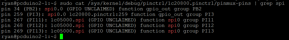
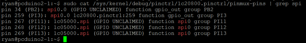
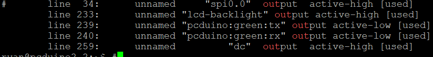
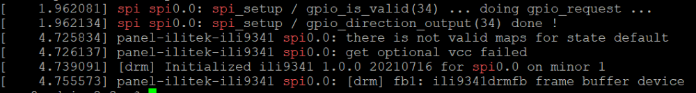
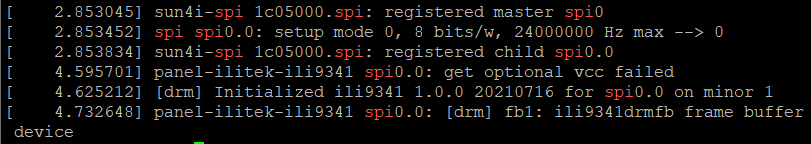
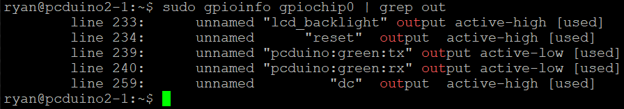
I have recently been trying to get my spi ili9341 working under kernel 6.6, having gotten it working previously. I checked to ensure there were no changes in the overlay required by the newer kernel. I confirmed that the pins were configured correctly and that the ILI9341 DRM module had loaded.. Despite this I was met with a white screen. Think I must have missed something I swapped out my SD card for another using an image based on kernel 5.15.88, where I was able to recieve a display. Looking back over the dmesg log, I noticed a slight difference in behaviour with the older kernel. firstly we can clearly see that the SPI driver is requesting to use gpio 34 as a chip select line compared to kernel 6.6. Secondly using gpioinfo to see which pins are currently set as output, to observe if gpio 34 has been set. A slight draw back with this approach is that it does not currently acknowledge when gpio are configured for spi. Kernel 5.15.88: Kernel 6.6.16: I later tried again but with my Pcduino3 using a more recent build based on kernel of 6.6.44 but achieved the same result. To confirm my theory that the problem lies somewhere within the chip select intialisation, I temporarily rerouted the pin used for the display to the Pcduino's native chip select pin (PI10) and recompiled the overlay to match. Now when I booted the pcduino I was met with a terminal window.
-
Hi, Running on Armbian_community 24.8.0-trunk.529 Bookworm with Linux 6.6.43-current-sunxi64 onthe orangepi zero3 And need to use the GPIO pins with python, not an expert here but have tried a few recommandations with no luck. Can anyone suggest method that works with the above OS/build please? Thanks! Rob.
-
Hello everyone, I'm currently working on a bananaPi M2S and trying to set up serial communication through the GPIO port on my device. I am using the provided overlay for UART-A. The overlay seems to work as it registers the serial device, as indicated by the dmesg output: bash [ 0.000277] printk: console [tty1] enabled [ 0.734433] ff803000.serial: ttyAML0 at MMIO 0xff803000 (irq = 14, base_baud = 1500000) is a meson_uart [ 0.734458] printk: console [ttyAML0] enabled [ 0.735241] ffd24000.serial: ttyAML6 at MMIO 0xffd24000 (irq = 15, base_baud = 1500000) is a meson_uart [ 0.735395] serial serial0: tty port ttyAML6 registered [ 2.663304] systemd[1]: Created slice Slice /system/serial-getty. [ 3.140660] systemd[1]: Found device /dev/ttyAML0. However, the device /dev/ttyAML6 does not appear in the /dev folder. Here are the steps I've taken so far: Loaded the UART-A overlay. Verified registration through dmesg logs, which show that ttyAML6 is indeed registered. What I've checked: I ran ls /dev/ttyAML* and /dev/tty* but didn't find ttyAML6. Questions: Is there a known issue with this overlay or an additional step I'm missing to make the device node appear in /dev? Are there specific udev rules I need to add or modify to automatically create the device node? Any help or pointers would be greatly appreciated! Thank you in advance!
-
 Hello, I bought a card which has an SK6805 LED onboard (https://www.tindie.com/products/hallard/ethtinfo-tic-teleinfo-reader-for-ethernet-esp32/) and I'm wondering if there is a way to control it from my BananaPI IO-8 ? Thanks
 -
Hi, I am new to Armbian, and I don't know how to control VIM3's GPIOs. Can someone help me please? I have Armbian bookworm 24.5.1, kernel 6.6.32-current-meson. Thank you!
-
Hi, I managed to make w1-GPIO work in Orange Pi Zero v3 for, for example, the DS18B20 sensor. However, I have some doubts about setting the GPIO flags for w1-gpio. Many examples provide flags in the form gpios = <&pio 0 7 (GPIO_ACTIVE_HIGH|GPIO_OPEN_DRAIN)>; but in the dts file when I use this form it does not work (syntax error) so I have to provide the flags in digital form. A description of flags and bits is here https://elixir.bootlin.com/linux/v6.6.30/source/include/dt-bindings/gpio/gpio.h If I would like to set GPIO_ACTIVE_HIGH | GPIO_OPEN_DRAIN then the digital value for these bits will be for set bits: 0110000 = 48 because GPIO_OPEN_DRAIN it is (GPIO_SINGLE_ENDED | GPIO_LINE_OPEN_DRAIN) Please help me and confirm whether I understood it correctly I wanted to get rid of the message in the logs for w1-gpio [ 4.994183] gpio-74 (onewire@0): enforced open drain please flag it properly in DT/ACPI DSDT/board file which understands that I need to set the GPIO flag GPIO_OPEN_DRAIN in the dts file I see one problem with this source https://www.kernel.org/doc/Documentation/devicetree/bindings/gpio/gpio.txt where a number of bits to set is 6 in source https://elixir.bootlin.com/linux/v6.6.30/source/include/dt-bindings/gpio/gpio.h number of bits to set is 7 I hope I posted this question in the right section, if not please move it
-
I have question. OZPI v3 has support for hardware DS18B20 thermal sensor via w1-gpio ? In armbian-config when we got to the “system” section and select “Hardware” is not existing w1-gpio or OZPI v3 has not support for w1-gpio hardware ? Does not work because there is no device tree file (in the /boot/dtb/allwinner/) and we need to create it ??? like for OZPI v2 ?: 1. Create text file "sun50i-h616-w1-gpio.dts" /dts-v1/; / { compatible = "xunlong,orangepi-zero2\0allwinner,sun50i-h616"; fragment@0 { target = <0xffffffff>; __overlay__ { w1_pins { pins = "PC9"; function = "gpio_in"; phandle = <0x01>; }; }; }; fragment@1 { target-path = [2f 00]; __overlay__ { onewire@0 { compatible = "w1-gpio"; pinctrl-names = "default"; pinctrl-0 = <0x01>; gpios = <0xffffffff 0x02 0x06 0x00>; status = "okay"; }; }; }; __symbols__ { w1_pins = "/fragment@0/__overlay__/w1_pins"; }; __fixups__ { pio = "/fragment@0:target:0\0/fragment@1/__overlay__/onewire@0:gpios:0"; }; __local_fixups__ { fragment@1 { __overlay__ { onewire@0 { pinctrl-0 = <0x00>; }; }; }; }; }; 2. After you need to compile it, with command "dtc -O dtb -o sun50i-h616-w1-gpio.dtbo sun50i-h616-w1-gpio.dts" 3. Copy it too /boot/dtb/allwinner/overlay/
-
Looking at the new BPI M4 zero to replace a RPI zero. The official build listed does not have gpio turned or maybe just not built into the kernel. If I download the image from the BPI website it has it but it based on bullseye and the image is broke. I built my own image but still no go so I am not sure what is wrong. I have built images for other boards and projects with success so that's not the problem. I have a 3.5" TFT touch screen and some relays that I need to run along with a sensor.
-
Hi I'm using an Orange Pi PC Plus with a LoRa HAT (Semtech SX1278) connected via GPIO. The tool which uses this HAT connects directly to the SX1278 chip on the HAT, no protocoll like SPI is needed. I'm using it for several years on RaspberryPi's without problems. But with the latest ARMBIAN Image for the Orange Pi PC Plus Armbian_23.11.1_Orangepipcplus_bookworm_current_6.1.63.img.xz I have issues in this constellation. The tool can not contact the SX1278 via GPIO, said the tool developer. It seems like I have to activate the GPIO pins before. I've tried to find information about that, but without success. So I hope to find here more information and help. I have to use these hardware PINs (these are the PIN descritions on teh Raspberry Pi): MOSI SPI0_MOSI / GPIO10 (PIN 19) MISO SPI0_MISO / GPIO9 (PIN 21) SCK SPI0_SCLK / GPIO11 (PIN 23) NSS/Enable SPI0_CE0_N / GPIO8 (PIN 24) RST GPIO6 (PIN 31) Thanks in advance.
-
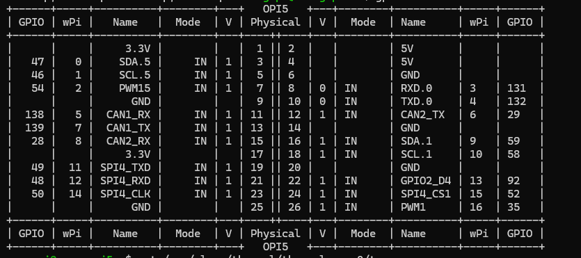
hello, i was trying to set up a 2 pin fan on my orangepi 5b and i connected it to pin 25 and 26 (GND and PWM1). When i first started this task, the output from gpio readall would show me all 26 pins on the board. As i was digging through some forums to try and get the PWM pin to operate as on/off, i came across wiringOP and when i installed it, the output of `gpio readall` changed to only show 8pins. I am unsure of what went wrong and why it only shows 8 pins. I tried removing wiringOP and it still has not made a difference. Thanks

-
Hi, Armbian_21.02.3_Odroidc1_focal_current_5.10.21 how do I find out which number do I need to provide to gpio export command? Let's say I have physical pin 16, which is labeled by the manufacturer as `GPIOX.5` or `102`. But that doesn't work with Armbian: echo 102 > /sys/class/gpio/export [ 1602.030617] export_store: invalid GPIO 102 How do I know the value to provide for /sys/class/gpio/export? # cat /sys/kernel/debug/gpio gpiochip1: GPIOs 413-428, parent: platform/c8100084.pinctrl, aobus-banks: gpio-416 ( |TF_IO ) out lo gpio-417 ( |usb-hub-reset ) out hi gpio-426 ( |c1:blue:alive ) out hi ACTIVE LOW gpiochip0: GPIOs 429-511, parent: platform/c1109880.pinctrl, cbus-banks: gpio-456 ( |regulator-tflash_vdd) out lo gpio-470 ( |PHY reset ) out hi ACTIVE LOW gpio-482 ( |cd ) in hi ACTIVE LOW gpio-492 ( |reset ) out hi ACTIVE LOW Thanks