All Activity
- Past hour
-

Need help with video decode acceleration on NanoPi R6S
Giuseppe93 replied to Blind55's topic in NanoPi R6S/R6C
I've a similar issue but on a different board nanopi m4v2. Could you also help me in troubleshooting the problem? In addition to video problems at 4K I'm getting also Bluetooth problems with my keyboard. Feel free to ask for extra info. - Today
-

mxq pro 4k 5g allwinner h313 can't sd card boot
Ducdanh Nguyen replied to Ducdanh Nguyen's topic in Allwinner CPU Boxes
@Sergey LepeshkinThank you, is there anyway to get it out and reveal the cpu (may fake, but worth trying) Also, i don't even know why they put a fake update screen on a fake tv box but i found a guy with same problem on me : I don't know what to do, my box does have the usb debugging and i will try to debug it -

i flashed the minimal image and its stuck on blue light please help
Igor replied to Aviad Korakin's topic in Radxa Rock 5B
Etcher used to be / is broken. https://docs.armbian.com/User-Guide_Getting-Started/#flash-to-sd-card https://docs.armbian.com/User-Guide_Troubleshooting/ -

Installing armbian on Yundoo Y8 TV box (RK3399)
SteeMan replied to FucusMeDeep's topic in Rockchip CPU Boxes
There are those of us that spend months working on these things. There is nothing about this that is easy. It is a hobby to waste a lot of time on. If you really wanted to proceed further you are really going to need to hook up to the debug serial port to get an ideal of the boot messages that are occuring. From an earlier post it looks like the serial connection points were identified and hooking up a USB serial adapter to them would give more information. But getting a random TV box working is usually a many month project as a lot needs to be learned about this while environment first. -

Installing armbian on Yundoo Y8 TV box (RK3399)
nobitakun replied to FucusMeDeep's topic in Rockchip CPU Boxes
Well, I've been tinkering with different dtb's and Armbian versions, matching kernel 4.4 and using H96 Max RK3399 dtb as well, but the device does nothing. In fact, I entered the recovery to see if the SD card could be read and it didn't mount, then turned the device off through the button and now it does not turn on anymore. The red light does not go blue, I can still enter maskrom but if I want to boot Android normaly the device does nothing. I am kind of tired with this crappy TV box, wasting 2 days it's not worth it for something that costed 15€. My time is more valuable. Thank you for the help anyways. -
Installing armbian on Yundoo Y8 TV box (RK3399)
nobitakun replied to FucusMeDeep's topic in Rockchip CPU Boxes
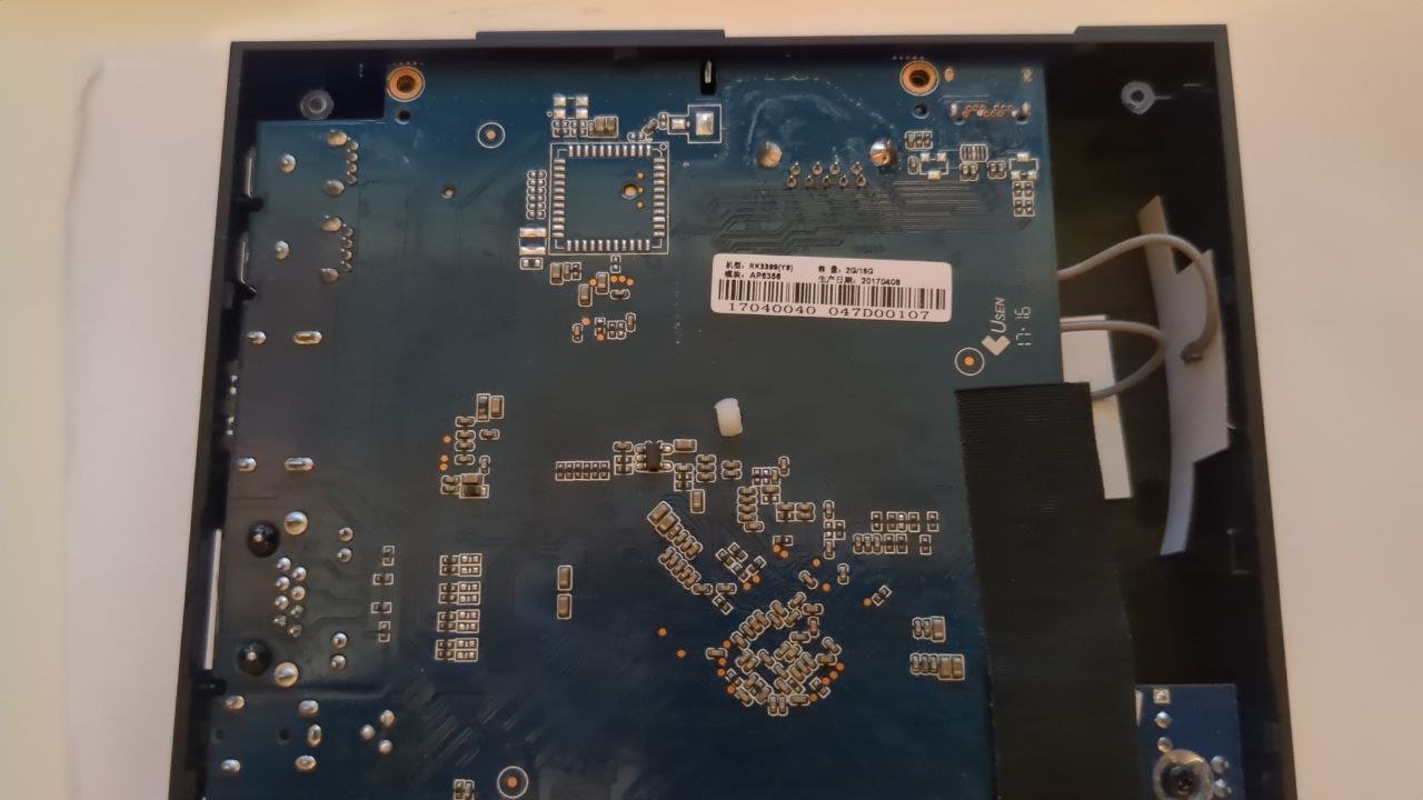
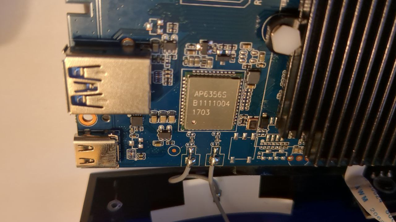
The dtb files I've tried for rk3399 do not work, I've read that Firefly-RK3399 is very similar to this board, but even so it does not start. The small Rockchip chip is very difficult to see through a picture, at least with my phone camera. I tried with this picture: Anyways, I can write it here: RK808-D FAD7P841 1703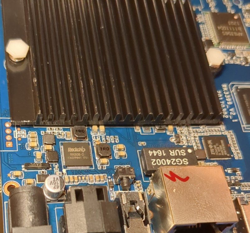
-

mxq pro 4k 5g allwinner h313 can't sd card boot
Sergey Lepeshkin replied to Ducdanh Nguyen's topic in Allwinner CPU Boxes
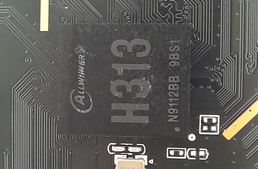
I've managed to pull out some system files out of it. Binaries is ELF 32-bit LSB executable, ARM, EABI5 version 1 (SYSV), so its not Allwinner H313. -
Try to upgrade from 25.5.1 but base-files not present in repository. Missed again. @Igor can you fix it?
-
mxq pro 4k 5g allwinner h313 can't sd card boot
Sergey Lepeshkin replied to Ducdanh Nguyen's topic in Allwinner CPU Boxes
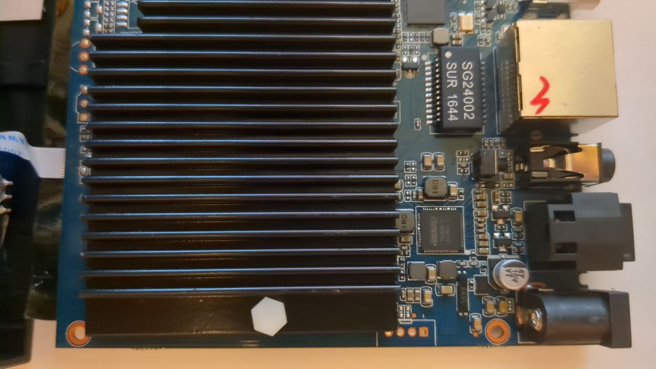
Hi! @Ducdanh Nguyen , which port have you used to connect it through adb? Those on the back side (where hdmi and power connectors located), or one of those on the right side (where sd card slot located)? Was it working in standard Android boot mode ("Debug over usb" enabled through "Developer settings") or somehow else? I also own such tv box and this is what I've found crawling web and playing with this device: 1. More PCB pics is here: https://4pda.to/forum/index.php?showtopic=1016510&view=findpost&p=136516719 2. "Heatsink" (just a small piece of thick aluminium foil) is bonded to SoC using 2-sided adhesive tape (I doubt it have good thermal conductivity). I recommend to replace it with more adequate heatsink. 3. SoC seems to be fake. It doesn't have Allwinner logo on it (there are 2 pics attached: one is ours, and one is genuine). 4. There is no AXP PMIC. Instead, there are 3 separate fixed step down converters. 5. There is no transformer in ethernet circuitry! Signals from jack goes directly to SoC. So be careful with static electricity while handling it's ethernet connection. 6. First button, located near "AV" jack, just resets tv box to factory defaults (if power switched on while it's pressed - and after that "update" screen with Chinese text on it will be shown). Purpose of second button (located near "S/PDIF" jack) is mystery for me. Can anyone suppose what it is for? 7. There are two exposed test points on the bottom side of pcb under SoC. Both tied through 10k resistors to +3.3V. After power-on, one of them seems to be some input (current between pin and gnd is about 3.3/10000=0.33mA), and other is definitely driven by something else (current is about 14mA and varying in both directions). I wonder if it's uart tx and rx pins - I'll see it with oscilloscope later. Anyway, shorting this test points together doesn't influence on boot process. 8. It's highly probable there is some backdoor (something like well-known Badbox 2.0). Original firmware exhibits some suspicious network behavior: just after factory reset, once it connected to network, it opens different connections to tcp port 12000 to hosts located in China. If I close outgoing traffic on firewall to tcp port 12000, after a while, it opens similar connections, but to port 9090 to different hosts. It seems to me it's trying to join some botnet. Furthermore, if you compare process list just after first (after factory reset) connection to network, and after it been connected for a while, you will find some new processes, which doesn't belong to Android and have strange names - I think it downloads something without asking user. Summary: this cheap tv box is a full scam. It seems to me manufacturer made all to prevent re-flashing of this device. But it will be very interesting to make something useful out of it.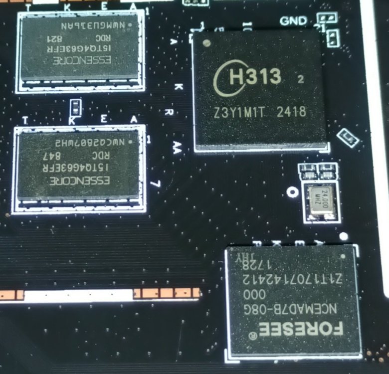

-

Debian Trixie : rolling release when building armbian
Stefal replied to Stefal's topic in Raspberry Pi
Regardless of which version I boot ("official" or home built with current) , the apt repositories are the same. And after I apt update && apt upgrade the "current" release, the "rolling" message disappears from the MOTD. I understand that I should not care of these MOTD messages, the meaning is not what I thought it was. -
 Title, i just download the right version used balenaEtcher for flashing it on microssd and its stuck on blue light(booting), how i can solve it
 -
 Hi @Ed van den Enden, Looks like the on-chip RTC is used for initial time-setting by the kernel in your case. It also seems that the overlay to enable i2c is now loaded correctly! I can help with two options, you can choose which one you want to use: Option 1: Use the `rtc-sync` script with the cronjob and systemd modification. Option 2: Use the user-overlay that will move the I2C "external" RTC to the first slot, naming it `rtc0`. The on-chip RTC will move to the second slot, `rtc1`. Option 1 will need more modifications in your configuration, but will work nonetheless. You can find the script attached here: Put the rtc-sync script in /usr/local/sbin/. Change onwership/permissions: sudo chown root:staff /usr/local/sbin/rtc-sync sudo chmod 0775 /usr/local/sbin/rtc-sync Create the cronjob /etc/cron.d/rtc-sync as follows: #min hr mon day dow run-as command 30 * * * * root /usr/local/sbin/rtc-sync -Ad update Modify ntp service unit file by adding the following to the end of the file (/lib/systemd/system/ntpsec.service OR /lib/systemd/system/ntp.service depending on which ntp package you have installed): # Added to sync wallclock to an external RTC [Service] ExecStartPre=-/usr/local/sbin/rtc-sync -A -d start ExecStopPost=-/usr/local/sbin/rtc-sync -A -d stop Option 2 will require adding the user-overlay file and changing only your armbianEnv.txt. I can only give you the user-overlay i used that works for the orangepi zero, but as this uses the same CPU as your board, it should work. if it does not work, you will always have option 1 as fallback. You can find the user-overlay (rtc1-soc.dts) and the instruction on how to compile and add this to armbianEnv.txt in this topic here: The user-overlay is also included down here: In addition to the user-overlay, you will also need to disable the `fake-hwclock` service, as that tries to emulate a real RTC by reloading the last known wallclock from a file that was created when the system was shutdown/rebooted. Instructions for this also in the same linked topic. Pick your option and try it out. If it all works well, for option 2 you will find that the i2c RTC is named rtc0, for option 1 you will see i2c RTC is still rtc1, but the rtc-sync script, cronjob and systemd modification will use the i2c RTC to set the wallclock (after it's set improperly by rtc0). Feel free to check back in if it still does not work. Groetjes,
 -
Maybe try another power adapter Or add to /boot/armbiEnv.txt extraargs=pcie_aspm=off nvme_core.default_ps_max_latency_us=0 pci=pcie_bus_safe Otherwise you could try an image of Radxa first, if that works then it might be an issue with the dtb
- Yesterday
-
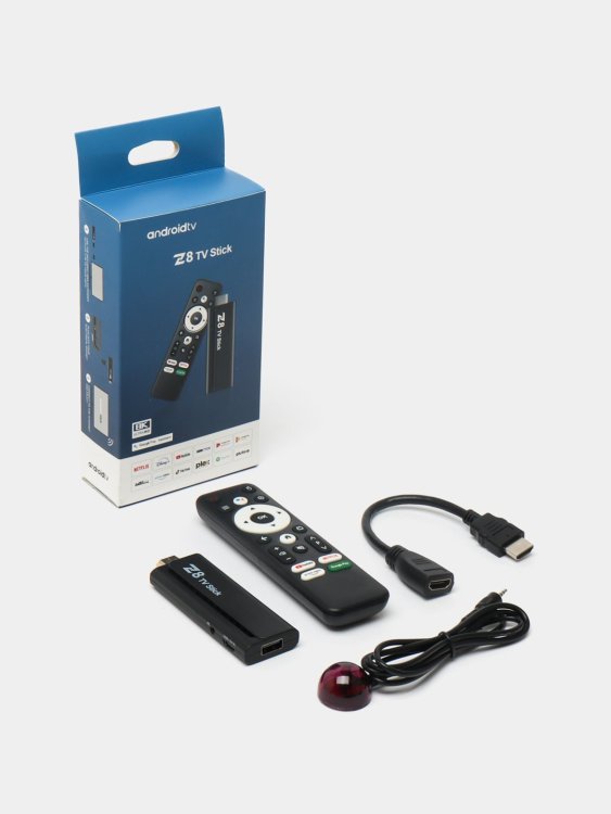
I have two of these cheap Chinese sticks and I was wondering if I could load a better OS onto them I think there's only a USB port

-

Need help with video decode acceleration on NanoPi R6S
Dantes replied to Blind55's topic in NanoPi R6S/R6C
Or wait until the end of the year when 6.18 will be the new Linux version, that enables pretty much everything. RK3588 Mainline Linux Status: https://gitlab.collabora.com/hardware-enablement/rockchip-3588/notes-for-rockchip-3588/-/blob/main/mainline-status.md If you really need a bleeding edge working mediaplayer, LibreElec has experimental support for R6S/R6C: Thread: https://forum.libreelec.tv/thread/29953-le13-testing-for-rk3288-rk3328-rk3399-rk3566-rk3568-rk3576-rk3588/ Downloads: https://chewitt.libreelec.tv/testing/ -
That's why I am here To ask for help I could not find any installable packages I am a novice user
-
Why? There is experimental support now for arm64/aarch64. It even has .deb packages https://nightlies.tbb.torproject.org/nightly-builds/tor-browser-builds /<date>/nightly-linux-aarch64/ Can't get closer to the source than that Edit: @c0rnelius: you were 48mins ahead of me
-

Installing armbian on Yundoo Y8 TV box (RK3399)
maka replied to FucusMeDeep's topic in Rockchip CPU Boxes
You can not use android dtb. You must try without It or try the rk3399 files included in the sdcard. i cant see the second rockchip (pmic) -

H3 cedrus video acceleration, device tree problem?
Ryzer replied to schunckt's topic in Allwinner sunxi
Firstly can you actually connect to the repo without issues? I my case I was getting timeouts and i suspect it was being blocked by my ISP for whatever reason and to work around I to tether my SBC to mobile for internet via mobile data then install the packages this way. This is my current ffmpeg: ffmpeg -version ffmpeg version 5.1.4-0+deb12u1.v4l2request Copyright (c) 2000-2023 the FFmpeg de velopers built with gcc 12 (Debian 12.2.0-14) configuration: --prefix=/usr --extra-version=0+deb12u1.v4l2request --toolchain=h ardened --libdir=/usr/lib/arm-linux-gnueabihf --incdir=/usr/include/arm-linux-gn ueabihf --arch=arm --enable-gpl --disable-stripping --enable-gnutls --enable-lad spa --enable-libaom --enable-libass --enable-libbluray --enable-libbs2b --enable -libcaca --enable-libcdio --enable-libcodec2 --enable-libdav1d --enable-libflite --enable-libfontconfig --enable-libfreetype --enable-libfribidi --enable-libgls lang --enable-libgme --enable-libgsm --enable-libjack --enable-libmp3lame --enab le-libmysofa --enable-libopenjpeg --enable-libopenmpt --enable-libopus --enable- libpulse --enable-librabbitmq --enable-librist --enable-librubberband --enable-l ibshine --enable-libsnappy --enable-libsoxr --enable-libspeex --enable-libsrt -- enable-libssh --enable-libsvtav1 --enable-libtheora --enable-libtwolame --enable -libv4l2 --enable-v4l2-request --enable-v4l2-m2m --enable-libvidstab --enable-li bvorbis --enable-libvpx --enable-libwebp --enable-libudev --enable-libx265 --ena ble-libxml2 --enable-libxvid --enable-libzimg --enable-libzmq --enable-libzvbi - -enable-lv2 --enable-omx --enable-openal --enable-opencl --enable-opengl --enabl e-sdl2 --disable-sndio --enable-libjxl --enable-pocketsphinx --enable-librsvg -- enable-libdc1394 --enable-libdrm --enable-libiec61883 --enable-chromaprint --ena ble-frei0r --enable-libx264 --enable-libplacebo --enable-librav1e --enable-share Admittedly not the most up to date as it has been a while since I last attempted. From what I can tell from the latest pages it looks like using drm* has now been replaced with v4l2request more recently. I doubt it would specifically related to the duo2 and more likely at the soc dtsi definitions level. Now I encountered many of the same problems you did earlier but the older A10/A20 VE is limited to physically access only the first 256mb of memory. The H3 does not have the same constraints. @robertoj You are using a more modern setup? what is your current reported ffmpeg version. -
Installing armbian on Yundoo Y8 TV box (RK3399)
nobitakun replied to FucusMeDeep's topic in Rockchip CPU Boxes
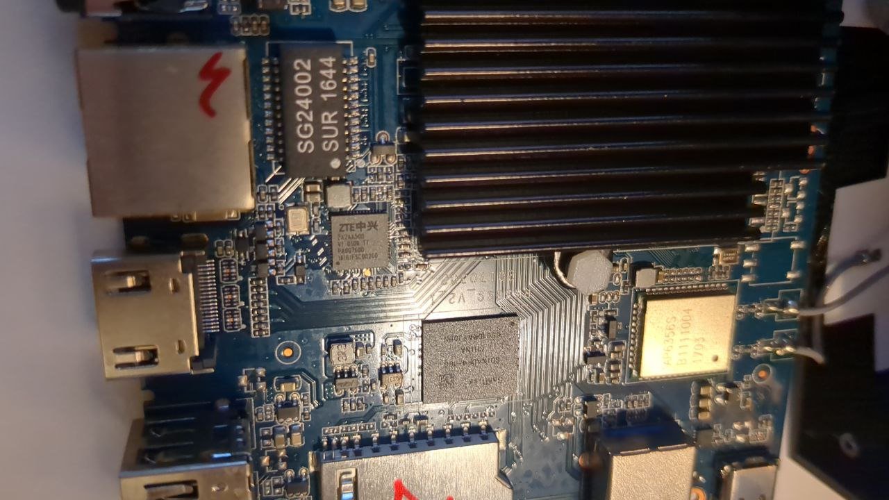
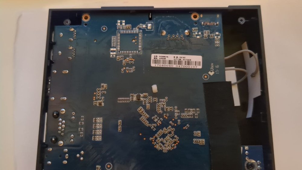
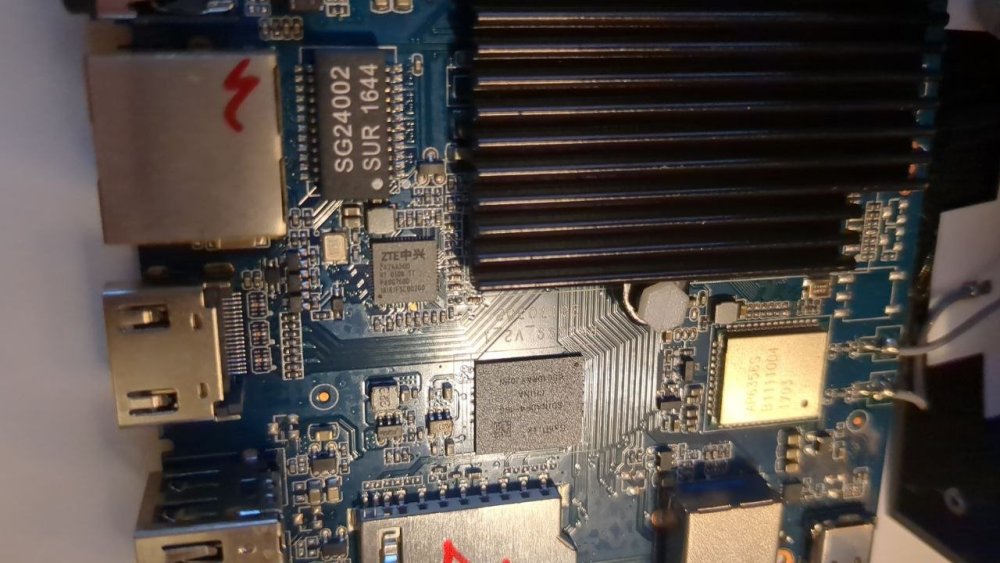
I attached some pictures of the device inside, I don't know if they can be of any help. I tried to use te dtb extracted from Android with the Armbian for Firefly-RK3399 and it does not boot. I configure the extlinux.conf file as advised, but the same moment I insert the SD card and turn on the device, the red light never turns blue. I tried that board because I've read in some forum that is similar to this device, but I know that's kind of hit and miss. At least I expected to see something on screen, even if it threw tons of errors, because I assume the dtb file is not the problem so the issue should be somewhere else that needs to be modified. Much appreciated for the help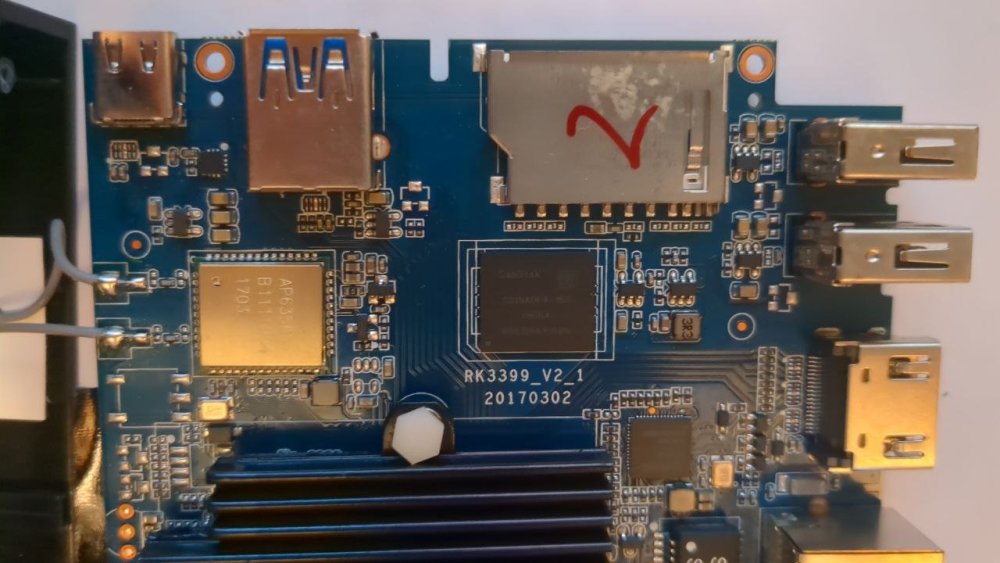


-
Dear all, I got myself an Radxa Rock 5 ITX+ as I thought I'd saw that this board had premium support. After it arrived, I saw that only the ITX (non-plus) variant had premium support, which since latest Armbian release some days ago seems to has been downgraded to standard support. I cleared both the eMMC and SPI flash to make sure the preinstalled OS were gone and would not interfere with the boot up process. Then I built myself a latest image with trixie and vendor kernel but I realized that (after booting from sdcard successfully), the Nvme was never picked up. The ITX+ has two M.2 full-size slots instead of only one - and is missing the SATA controller instead. To make sure I did nothing wrong with the building process I grabbed myself some old images like e.g. Armbian_24.11.1_Rock-5-itx_bookworm_vendor_6.1.75_cinnamon-backported-mesa_desktop.img.xz Armbian_25.2.2_Rock-5-itx_bookworm_vendor_6.1.99_cinnamon-backported-mesa_desktop.img.xz but they don't show working Nvmes either. So I got myself the latest nightly Trixie build (Rolling releases images with Armbian Linux v6.1 / Build Date: Sep 6, 2025 / Debian Debian 13 (Trixie)) from https://www.armbian.com/radxa-rock-5-itx/ and booted that, to also see that both populated Nvme slots are not picked up. lspci shows two Nvmes: 0000:01:00.0 Non-Volatile memory controller: Solid State Storage Technology Corporation NVMe SSD M.2 (rev 01) 0001:11:00.0 Non-Volatile memory controller: Solid State Storage Technology Corporation NVMe SSD M.2 (rev 01) Bot dmesg shows issues during boot: [ 14.165404] pci 0001:10:00.0: Primary bus is hard wired to 0 [ 14.165410] pci 0001:10:00.0: bridge configuration invalid ([bus 01-ff]), reconfiguring [ 14.165514] pci 0001:11:00.0: [1e95:3500] type 00 class 0x010802 [ 14.165568] pci 0001:11:00.0: reg 0x10: [mem 0x00000000-0x00003fff 64bit] [ 14.165794] pci_bus 0000:01: busn_res: can not insert [bus 01-ff] under [bus 00-0f] (conflicts with (null) [bus 00-0f]) [ 14.165901] pci 0000:01:00.0: [1e95:3500] type 00 class 0x010802 [ 14.166009] pci 0000:01:00.0: reg 0x10: [mem 0x00000000-0x00003fff 64bit] [ 14.166147] pci 0001:11:00.0: 15.752 Gb/s available PCIe bandwidth, limited by 8.0 GT/s PCIe x2 link at 0001:10:00.0 (capable of 31.504 Gb/s with 8.0 GT/s PCIe x4 link) [ 14.166379] cpu cpu6: l=15000 h=85000 hyst=5000 l_limit=0 h_limit=2208000000 h_table=0 [ 14.166699] pci_bus 0001:11: busn_res: [bus 11-1f] end is updated to 11 [ 14.166721] pci 0001:10:00.0: BAR 8: assigned [mem 0xf1200000-0xf12fffff] [ 14.166729] pci 0001:10:00.0: BAR 6: assigned [mem 0xf1300000-0xf130ffff pref] [ 14.166729] pci 0000:01:00.0: 15.752 Gb/s available PCIe bandwidth, limited by 8.0 GT/s PCIe x2 link at 0000:00:00.0 (capable of 31.504 Gb/s with 8.0 GT/s PCIe x4 link) [ 14.166737] pci 0001:11:00.0: BAR 0: assigned [mem 0xf1200000-0xf1203fff 64bit] [ 14.166785] pci 0001:10:00.0: PCI bridge to [bus 11] [ 14.166792] pci 0001:10:00.0: bridge window [mem 0xf1200000-0xf12fffff] [ 14.168281] pcieport 0001:10:00.0: PME: Signaling with IRQ 128 [ 14.168548] nvme nvme0: pci function 0001:11:00.0 [ 14.168576] nvme 0001:11:00.0: enabling device (0000 -> 0002) [ 14.176536] pci 0000:00:00.0: BAR 8: assigned [mem 0xf0200000-0xf02fffff] [ 14.176542] pci 0000:00:00.0: BAR 6: assigned [mem 0xf0300000-0xf030ffff pref] [ 14.176546] pci 0000:01:00.0: BAR 0: assigned [mem 0xf0200000-0xf0203fff 64bit] [ 14.176569] pci 0000:00:00.0: PCI bridge to [bus 01-ff] [ 14.176573] pci 0000:00:00.0: bridge window [mem 0xf0200000-0xf02fffff] [ 14.177418] pcieport 0000:00:00.0: PME: Signaling with IRQ 138 [ 14.177557] nvme nvme1: pci function 0000:01:00.0 [ 14.177582] nvme 0000:01:00.0: enabling device (0000 -> 0002) [ 14.181202] nvme nvme0: Removing after probe failure status: -19 [ 14.185702] cpu cpu6: EM: OPP:1008000 is inefficient [ 14.185716] cpu cpu6: EM: OPP:816000 is inefficient [ 14.185965] cpu cpu6: EM: created perf domain [ 14.190212] nvme nvme1: Removing after probe failure status: -19 ( full log: https://paste.next.armbian.com/labujaguke.yaml ) Any idea on how to fix this and get them working? That would be really lovely, Thanks a lot for all your support!
-
OK...I think it worked in OrangePi3 LTS 🙂 ...first, clean up the remnants: ................................................................. sudo apt purge v4l2loopback-dkms sudo apt autoremove ............................................................... armbian-config then I had to switch to a different kernel: edge:6.15.4-edge-sunxi64 ....then update the system: apt update / upgrade / reboot ! install from GitHub: v4l2loopback and then: cd ~/v4l2loopback .................................................................... VERSION=$(grep -oP 'PACKAGE_VERSION="\K[^"]+' dkms.conf) sudo cp -r . /usr/src/v4l2loopback-$VERSION sudo dkms add -m v4l2loopback -v $VERSION sudo dkms build -m v4l2loopback -v $VERSION sudo dkms install -m v4l2loopback -v $VERSION dkms status sudo modprobe v4l2loopback ls /dev/video* ................................................................... I guess it's OK now: ................................................................ but in my opinion the module is not working properly 😞
-
It doesn't seem to make a difference:
-
aplay -D plughw:0,0 -f S16_LE -r 48000 -c 2 your_audio_file.wav ? this will force a more common audio format (in case the monitor supports specific audio formats. If not working, no idea, hw detection looks ok.
-
Sorry I mean Which kind of output device: TV, Monitor with build in speakers? I have a HDMI monitor with speakers included. Yes.