


pzw
-
Posts
96 -
Joined
-
Last visited
Content Type
Forums
Store
Crowdfunding
Applications
Events
Raffles
Community Map
Posts posted by pzw
-
-
22 hours ago, Jens Bauer said:
Yep. They have acknowledged it and said that they're fixing the problem for next revision which should be out in "less than two months" (they've probably already fixed the schematics and PCB-layout, but I guess actual production slow down things).
As a workaround, wouldn't it be possible to disconnect CC1 or CC2 or both and then add the resistor inside an adapter-cable [USB-C female-to-male] ?
If you go through the hassle of creating a female - male adapter, then you do not need to cut the CC1/CC2 lines I think ;-) .
-
On 4/29/2019 at 4:35 PM, Jeffrey Walton said:
Armbian provided the software
Wait.... The tone of your message, and the lack of used words, indicate that you do not get the concept of free open source software.
You haven't paid a dime for it but expect, and basically insist judging from your messages, that you get support.
I think @Igor was very clear, and friendly, in pointing you in the direction how to solve the issue. If you expect more, find a commercial distribution which runs on your hardware, which has the option to buy commercial support.
-
-
Hi @NicoD;
Thanks for your reply, it did help for sure. To answer some questions;
- 1 GB should be enough I think, but if I can get for a small extra fee 2GB I would be happy.
- Power efficiency is not a big thing, same for voltage. Whatever it needs I can supply. (Using active POE, which allows a lot of options :-)
- Physical size is not important, as long as it is not the size of a PC! haha
Some remarks / questions about the boards you mention...:
NEO4 --> Not enough USB connectors. I would like to avoid an "external" USB hub
NEO3 --> Can't find it. But the description you give points me to the Fire3? But same thing, not enough USB connectors.
T3+ --> Enough USB connections! :-) You mention the lower per core performance. How can I compare it to a "H3" core? It is also one of the more expensive ones, basically the same as the M4. Which one will perform better?
Reading your post I think the M4 will be the best choice so far. Maybe someone else has another option?
-
I am looking to replace 3 OrangePi boards with a H3 CPU with one board. Every board has a RTL-SDR USB stick attached to it, and the software tends to load up the CPU a lot on at least one core, in some cases the total load is high on 2 cores. To make it all easier / simpler I would like to replace the 3 with one board with enough processing power, but nothing extreme. The goal is that it will be in an enclosure up the antenna mast, POE fed, so not easily accessible! I even looked at the Atomic Pi, but I am not so sure about processing power in that unit.. (I might be wrong though!)
Browsing the options online, I saw the NanoPi M4 which looks like a good candidate to me. Another one is the Odroid-N2, but there is no armbian support for it (yet).
Without a doubt I have missed good candidates, therefore my question to the community... Anyone with a good suggestion? Anything H2/H3/H5 will not do it performance wise I think. Maybe a H6 based board?
Thanks in advance for your time and help! :-)
-
Why don't you give etcher a try?
-
-
Hi @martinayotte ; Thanks for that hint :-) . I changed the extension and it looks like it is still not loading. Where can I find / set which dtb is being loaded at boot time?
This is what I have at the moment in the /boot/dtb-4.19.25-sunxi dir:
root@nanopiduo2:/boot/dtb-4.19.25-sunxi# dtc -o sun8i-h3-nanopi-duo2.dtb sun8i-h3-nanopi-duo2.dts
sun8i-h3-nanopi-duo2.dtb: Warning (unit_address_vs_reg): Node /opp_table0/opp@120000000 has a unit name, but no reg property
sun8i-h3-nanopi-duo2.dtb: Warning (unit_address_vs_reg): Node /opp_table0/opp@240000000 has a unit name, but no reg property
sun8i-h3-nanopi-duo2.dtb: Warning (unit_address_vs_reg): Node /opp_table0/opp@480000000 has a unit name, but no reg property
sun8i-h3-nanopi-duo2.dtb: Warning (unit_address_vs_reg): Node /opp_table0/opp@648000000 has a unit name, but no reg property
sun8i-h3-nanopi-duo2.dtb: Warning (unit_address_vs_reg): Node /opp_table0/opp@816000000 has a unit name, but no reg property
sun8i-h3-nanopi-duo2.dtb: Warning (unit_address_vs_reg): Node /opp_table0/opp@960000000 has a unit name, but no reg property
sun8i-h3-nanopi-duo2.dtb: Warning (unit_address_vs_reg): Node /opp_table0/opp@1008000000 has a unit name, but no reg property
sun8i-h3-nanopi-duo2.dtb: Warning (simple_bus_reg): Node /soc/eeprom@01c14000 simple-bus unit address format error, expected "1c14000"
sun8i-h3-nanopi-duo2.dtb: Warning (simple_bus_reg): Node /soc/sound missing or empty reg/ranges property
root@nanopiduo2:/boot/dtb-4.19.25-sunxi# ls *duo2*
sun8i-h3-nanopi-duo2.dtb  sun8i-h3-nanopi-duo2.dts
root@nanopiduo2:/boot/dtb-4.19.25-sunxi#
Do you have more pointers? :-)
Thanks in advance!
Paul
-
This is what I see when I run dmesg:
[    9.119901] core: _opp_supported_by_regulators: OPP minuV: 1320000 maxuV: 1320000, not supported by regulator
[    9.119929] cpu cpu0: _opp_add: OPP not supported by regulators (1056000000)
[    9.120409] core: _opp_supported_by_regulators: OPP minuV: 1320000 maxuV: 1320000, not supported by regulator
[    9.120445] cpu cpu0: _opp_add: OPP not supported by regulators (1104000000)
[    9.120645] core: _opp_supported_by_regulators: OPP minuV: 1320000 maxuV: 1320000, not supported by regulator
[    9.120659] cpu cpu0: _opp_add: OPP not supported by regulators (1152000000)
[    9.120859] core: _opp_supported_by_regulators: OPP minuV: 1320000 maxuV: 1320000, not supported by regulator
[    9.120874] cpu cpu0: _opp_add: OPP not supported by regulators (1200000000)
[    9.121078] core: _opp_supported_by_regulators: OPP minuV: 1340000 maxuV: 1340000, not supported by regulator
[    9.121095] cpu cpu0: _opp_add: OPP not supported by regulators (1224000000)
[    9.121256] core: _opp_supported_by_regulators: OPP minuV: 1340000 maxuV: 1340000, not supported by regulator
[    9.121282] cpu cpu0: _opp_add: OPP not supported by regulators (1248000000)
[    9.121545] core: _opp_supported_by_regulators: OPP minuV: 1340000 maxuV: 1340000, not supported by regulator
[    9.121566] cpu cpu0: _opp_add: OPP not supported by regulators (1296000000)
[    9.121848] core: _opp_supported_by_regulators: OPP minuV: 1400000 maxuV: 1400000, not supported by regulator
[    9.121865] cpu cpu0: _opp_add: OPP not supported by regulators (1344000000)
[    9.122055] core: _opp_supported_by_regulators: OPP minuV: 1400000 maxuV: 1400000, not supported by regulator
[    9.122088] cpu cpu0: _opp_add: OPP not supported by regulators (1368000000)
I have created a .dts / .dto without these setpoints, so it looks like it is not being loaded. It is named sun8i-h3-nanopi-duo2.dto .
The contents are: (of the .dts)
Spoiler/dts-v1/;
/ {
interrupt-parent = <0x1>;
#address-cells = <0x1>;
#size-cells = <0x1>;
model = "FriendlyARM NanoPi DUO2";
compatible = "friendlyarm,nanopi-duo", "allwinner,sun8i-h3";chosen {
#address-cells = <0x1>;
#size-cells = <0x1>;
ranges;
stdout-path = "serial0:115200n8";framebuffer-hdmi {
compatible = "allwinner,simple-framebuffer", "simple-framebuffer";
allwinner,pipeline = "mixer0-lcd0-hdmi";
clocks = <0x2 0x6 0x3 0x66 0x3 0x6f>;
status = "disabled";
};framebuffer-tve {
compatible = "allwinner,simple-framebuffer", "simple-framebuffer";
allwinner,pipeline = "mixer1-lcd1-tve";
clocks = <0x2 0x7 0x3 0x67>;
status = "disabled";
};
};clocks {
#address-cells = <0x1>;
#size-cells = <0x1>;
ranges;osc24M_clk {
#clock-cells = <0x0>;
compatible = "fixed-clock";
clock-frequency = <0x16e3600>;
clock-output-names = "osc24M";
phandle = <0xe>;
};osc32k_clk {
#clock-cells = <0x0>;
compatible = "fixed-clock";
clock-frequency = <0x8000>;
clock-output-names = "osc32k";
phandle = <0xf>;
};ext_osc32k_clk {
#clock-cells = <0x0>;
compatible = "fixed-clock";
clock-frequency = <0x8000>;
clock-output-names = "ext_osc32k";
phandle = <0x20>;
};internal-osc-clk {
#clock-cells = <0x0>;
compatible = "fixed-clock";
clock-frequency = <0xf42400>;
clock-accuracy = <0x11e1a300>;
clock-output-names = "iosc";
phandle = <0x21>;
};
};opp_table0 {
compatible = "operating-points-v2";
opp-shared;
phandle = <0x27>;opp@120000000 {
opp-hz = <0x0 0x7270e00>;
opp-microvolt = <0xfde80 0xfde80 0x13d620>;
clock-latency-ns = <0x3b9b0>;
};opp@240000000 {
opp-hz = <0x0 0xe4e1c00>;
opp-microvolt = <0xfde80 0xfde80 0x13d620>;
clock-latency-ns = <0x3b9b0>;
};opp@480000000 {
opp-hz = <0x0 0x1c9c3800>;
opp-microvolt = <0xfde80 0xfde80 0x13d620>;
clock-latency-ns = <0x3b9b0>;
};opp@648000000 {
opp-hz = <0x0 0x269fb200>;
opp-microvolt = <0xfde80 0xfde80 0x13d620>;
clock-latency-ns = <0x3b9b0>;
};opp@816000000 {
opp-hz = <0x0 0x30a32c00>;
opp-microvolt = <0x10c8e0 0x10c8e0 0x13d620>;
clock-latency-ns = <0x3b9b0>;
};opp@960000000 {
opp-hz = <0x0 0x39387000>;
opp-microvolt = <0x124f80 0x124f80 0x13d620>;
clock-latency-ns = <0x3b9b0>;
};opp@1008000000 {
opp-hz = <0x0 0x3c14dc00>;
opp-microvolt = <0x124f80 0x124f80 0x13d620>;
clock-latency-ns = <0x3b9b0>;
};
};display-engine {
compatible = "allwinner,sun8i-h3-display-engine";
allwinner,pipelines = <0x4>;
status = "disabled";
phandle = <0x2c>;
};soc {
compatible = "simple-bus";
#address-cells = <0x1>;
#size-cells = <0x1>;
ranges;clock@1000000 {
reg = <0x1000000 0x100000>;
clocks = <0x3 0x65 0x3 0x30>;
clock-names = "mod", "bus";
resets = <0x3 0x22>;
#clock-cells = <0x1>;
#reset-cells = <0x1>;
compatible = "allwinner,sun8i-h3-de2-clk";
phandle = <0x2>;
};mixer@1100000 {
compatible = "allwinner,sun8i-h3-de2-mixer-0";
reg = <0x1100000 0x100000>;
clocks = <0x2 0x0 0x2 0x6>;
clock-names = "bus", "mod";
resets = <0x2 0x0>;
phandle = <0x4>;ports {
#address-cells = <0x1>;
#size-cells = <0x0>;port@1 {
reg = <0x1>;
phandle = <0x2d>;endpoint {
remote-endpoint = <0x5>;
phandle = <0x6>;
};
};
};
};syscon@1c00000 {
compatible = "allwinner,sun8i-h3-system-controller", "syscon";
reg = <0x1c00000 0x1000>;
phandle = <0x10>;
};dma-controller@1c02000 {
compatible = "allwinner,sun8i-h3-dma";
reg = <0x1c02000 0x1000>;
interrupts = <0x0 0x32 0x4>;
clocks = <0x3 0x15>;
resets = <0x3 0x6>;
#dma-cells = <0x1>;
phandle = <0x13>;
};lcd-controller@1c0c000 {
compatible = "allwinner,sun8i-h3-tcon-tv", "allwinner,sun8i-a83t-tcon-tv";
reg = <0x1c0c000 0x1000>;
interrupts = <0x0 0x56 0x4>;
clocks = <0x3 0x2a 0x3 0x66>;
clock-names = "ahb", "tcon-ch1";
resets = <0x3 0x1b>;
reset-names = "lcd";
phandle = <0x2e>;ports {
#address-cells = <0x1>;
#size-cells = <0x0>;port@0 {
reg = <0x0>;
phandle = <0x2f>;endpoint {
remote-endpoint = <0x6>;
phandle = <0x5>;
};
};port@1 {
#address-cells = <0x1>;
#size-cells = <0x0>;
reg = <0x1>;
phandle = <0x30>;endpoint@1 {
reg = <0x1>;
remote-endpoint = <0x7>;
phandle = <0x1e>;
};
};
};
};mmc@1c0f000 {
reg = <0x1c0f000 0x1000>;
pinctrl-names = "default";
pinctrl-0 = <0x8>;
resets = <0x3 0x7>;
reset-names = "ahb";
interrupts = <0x0 0x3c 0x4>;
status = "okay";
#address-cells = <0x1>;
#size-cells = <0x0>;
compatible = "allwinner,sun7i-a20-mmc";
clocks = <0x3 0x16 0x3 0x47 0x3 0x49 0x3 0x48>;
clock-names = "ahb", "mmc", "output", "sample";
bus-width = <0x4>;
cd-gpios = <0x9 0x5 0x6 0x1>;
vmmc-supply = <0xa>;
phandle = <0x31>;
};mmc@1c10000 {
reg = <0x1c10000 0x1000>;
pinctrl-names = "default";
pinctrl-0 = <0xb>;
resets = <0x3 0x8>;
reset-names = "ahb";
interrupts = <0x0 0x3d 0x4>;
status = "disabled";
#address-cells = <0x1>;
#size-cells = <0x0>;
compatible = "allwinner,sun7i-a20-mmc";
clocks = <0x3 0x17 0x3 0x4a 0x3 0x4c 0x3 0x4b>;
clock-names = "ahb", "mmc", "output", "sample";
phandle = <0x32>;
};mmc@1c11000 {
reg = <0x1c11000 0x1000>;
resets = <0x3 0x9>;
reset-names = "ahb";
interrupts = <0x0 0x3e 0x4>;
status = "okay";
#address-cells = <0x1>;
#size-cells = <0x0>;
compatible = "allwinner,sun7i-a20-mmc";
clocks = <0x3 0x18 0x3 0x4d 0x3 0x4f 0x3 0x4e>;
clock-names = "ahb", "mmc", "output", "sample";
pinctrl-names = "default";
pinctrl-0 = <0xc>;
vmmc-supply = <0xa>;
bus-width = <0x8>;
non-removable;
cap-mmc-hw-reset;
phandle = <0x33>;
};usb@1c19000 {
compatible = "allwinner,sun8i-h3-musb";
reg = <0x1c19000 0x400>;
clocks = <0x3 0x20>;
resets = <0x3 0x11>;
interrupts = <0x0 0x47 0x4>;
interrupt-names = "mc";
phys = <0xd 0x0>;
phy-names = "usb";
extcon = <0xd 0x0>;
status = "okay";
dr_mode = "peripheral";
phandle = <0x34>;
};eeprom@01c14000 {
compatible = "allwinner,sun8i-h3-sid";
reg = <0x1c14000 0x400>;
phandle = <0x35>;
};phy@1c19400 {
compatible = "allwinner,sun8i-h3-usb-phy";
reg = <0x1c19400 0x2c 0x1c1a800 0x4 0x1c1b800 0x4 0x1c1c800 0x4 0x1c1d800 0x4>;
reg-names = "phy_ctrl", "pmu0", "pmu1", "pmu2", "pmu3";
clocks = <0x3 0x58 0x3 0x59 0x3 0x5a 0x3 0x5b>;
clock-names = "usb0_phy", "usb1_phy", "usb2_phy", "usb3_phy";
resets = <0x3 0x0 0x3 0x1 0x3 0x2 0x3 0x3>;
reset-names = "usb0_reset", "usb1_reset", "usb2_reset", "usb3_reset";
status = "okay";
#phy-cells = <0x1>;
usb0_id_det-gpios = <0x9 0x6 0xc 0x0>;
phandle = <0xd>;
};usb@1c1a000 {
compatible = "allwinner,sun8i-h3-ehci", "generic-ehci";
reg = <0x1c1a000 0x100>;
interrupts = <0x0 0x48 0x4>;
clocks = <0x3 0x21 0x3 0x25>;
resets = <0x3 0x12 0x3 0x16>;
status = "okay";
phandle = <0x36>;
};usb@1c1a400 {
compatible = "allwinner,sun8i-h3-ohci", "generic-ohci";
reg = <0x1c1a400 0x100>;
interrupts = <0x0 0x49 0x4>;
clocks = <0x3 0x21 0x3 0x25 0x3 0x5c>;
resets = <0x3 0x12 0x3 0x16>;
status = "okay";
phandle = <0x37>;
};usb@1c1b000 {
compatible = "allwinner,sun8i-h3-ehci", "generic-ehci";
reg = <0x1c1b000 0x100>;
interrupts = <0x0 0x4a 0x4>;
clocks = <0x3 0x22 0x3 0x26>;
resets = <0x3 0x13 0x3 0x17>;
phys = <0xd 0x1>;
phy-names = "usb";
status = "disabled";
phandle = <0x38>;
};usb@1c1b400 {
compatible = "allwinner,sun8i-h3-ohci", "generic-ohci";
reg = <0x1c1b400 0x100>;
interrupts = <0x0 0x4b 0x4>;
clocks = <0x3 0x22 0x3 0x26 0x3 0x5d>;
resets = <0x3 0x13 0x3 0x17>;
phys = <0xd 0x1>;
phy-names = "usb";
status = "disabled";
phandle = <0x39>;
};usb@1c1c000 {
compatible = "allwinner,sun8i-h3-ehci", "generic-ehci";
reg = <0x1c1c000 0x100>;
interrupts = <0x0 0x4c 0x4>;
clocks = <0x3 0x23 0x3 0x27>;
resets = <0x3 0x14 0x3 0x18>;
phys = <0xd 0x2>;
phy-names = "usb";
status = "disabled";
phandle = <0x3a>;
};usb@1c1c400 {
compatible = "allwinner,sun8i-h3-ohci", "generic-ohci";
reg = <0x1c1c400 0x100>;
interrupts = <0x0 0x4d 0x4>;
clocks = <0x3 0x23 0x3 0x27 0x3 0x5e>;
resets = <0x3 0x14 0x3 0x18>;
phys = <0xd 0x2>;
phy-names = "usb";
status = "disabled";
phandle = <0x3b>;
};usb@1c1d000 {
compatible = "allwinner,sun8i-h3-ehci", "generic-ehci";
reg = <0x1c1d000 0x100>;
interrupts = <0x0 0x4e 0x4>;
clocks = <0x3 0x24 0x3 0x28>;
resets = <0x3 0x15 0x3 0x19>;
phys = <0xd 0x3>;
phy-names = "usb";
status = "okay";
phandle = <0x3c>;
};usb@1c1d400 {
compatible = "allwinner,sun8i-h3-ohci", "generic-ohci";
reg = <0x1c1d400 0x100>;
interrupts = <0x0 0x4f 0x4>;
clocks = <0x3 0x24 0x3 0x28 0x3 0x5f>;
resets = <0x3 0x15 0x3 0x19>;
phys = <0xd 0x3>;
phy-names = "usb";
status = "okay";
phandle = <0x3d>;
};clock@1c20000 {
reg = <0x1c20000 0x400>;
clocks = <0xe 0xf>;
clock-names = "hosc", "losc";
#clock-cells = <0x1>;
#reset-cells = <0x1>;
compatible = "allwinner,sun8i-h3-ccu";
phandle = <0x3>;
};pinctrl@1c20800 {
reg = <0x1c20800 0x400>;
interrupts = <0x0 0xb 0x4 0x0 0x11 0x4>;
clocks = <0x3 0x36 0xe 0xf>;
clock-names = "apb", "hosc", "losc";
gpio-controller;
#gpio-cells = <0x3>;
interrupt-controller;
#interrupt-cells = <0x3>;
compatible = "allwinner,sun8i-h3-pinctrl";
phandle = <0x9>;csi {
pins = "PE0", "PE1", "PE2", "PE3", "PE4", "PE5", "PE6", "PE7", "PE8", "PE9", "PE10", "PE11";
function = "csi";
phandle = <0x1f>;
};emac0 {
pins = "PD0", "PD1", "PD2", "PD3", "PD4", "PD5", "PD7", "PD8", "PD9", "PD10", "PD12", "PD13", "PD15", "PD16", "PD17";
function = "emac";
drive-strength = <0x28>;
phandle = <0x3e>;
};i2c0 {
pins = "PA11", "PA12";
function = "i2c0";
phandle = <0x1a>;
};i2c1 {
pins = "PA18", "PA19";
function = "i2c1";
phandle = <0x1b>;
};i2c2 {
pins = "PE12", "PE13";
function = "i2c2";
phandle = <0x1c>;
};i2s0 {
pins = "PA18", "PA19", "PA20", "PA21";
function = "i2s0";
phandle = <0x3f>;
};i2s1 {
pins = "PG10", "PG11", "PG12", "PG13";
function = "i2s1";
phandle = <0x40>;
};mmc0 {
pins = "PF0", "PF1", "PF2", "PF3", "PF4", "PF5";
function = "mmc0";
drive-strength = <0x1e>;
bias-pull-up;
phandle = <0x8>;
};mmc1 {
pins = "PG0", "PG1", "PG2", "PG3", "PG4", "PG5";
function = "mmc1";
drive-strength = <0x1e>;
bias-pull-up;
phandle = <0xb>;
};mmc2_8bit {
pins = "PC5", "PC6", "PC8", "PC9", "PC10", "PC11", "PC12", "PC13", "PC14", "PC15", "PC16";
function = "mmc2";
drive-strength = <0x28>;
bias-pull-up;
phandle = <0xc>;
};spdif {
pins = "PA17";
function = "spdif";
phandle = <0x41>;
};spi0 {
pins = "PC0", "PC1", "PC2", "PC3";
function = "spi0";
phandle = <0x14>;
};spi1 {
pins = "PA15", "PA16", "PA14", "PA13";
function = "spi1";
phandle = <0x15>;
};uart0 {
pins = "PA4", "PA5";
function = "uart0";
phandle = <0x19>;
};uart1 {
pins = "PG6", "PG7";
function = "uart1";
phandle = <0x42>;
};uart1_rts_cts {
pins = "PG8", "PG9";
function = "uart1";
phandle = <0x43>;
};uart2 {
pins = "PA0", "PA1";
function = "uart2";
phandle = <0x44>;
};uart3 {
pins = "PA13", "PA14";
function = "uart3";
phandle = <0x45>;
};uart3_rts_cts {
pins = "PA15", "PA16";
function = "uart3";
phandle = <0x46>;
};led_pins {
pins = "PA10";
function = "gpio_out";
phandle = <0x28>;
};
};thermal-sensor@1c25000 {
reg = <0x1c25000 0x100>;
interrupts = <0x0 0x1f 0x4>;
clocks = <0x3 0x37 0x3 0x45>;
clock-names = "bus", "mod";
resets = <0x3 0x2a>;
#io-channel-cells = <0x0>;
compatible = "allwinner,sun8i-h3-ths";
#thermal-sensor-cells = <0x0>;
phandle = <0x24>;
};timer@1c20c00 {
compatible = "allwinner,sun4i-a10-timer";
reg = <0x1c20c00 0xa0>;
interrupts = <0x0 0x12 0x4 0x0 0x13 0x4>;
clocks = <0xe>;
};ethernet@1c30000 {
compatible = "allwinner,sun8i-h3-emac";
syscon = <0x10>;
reg = <0x1c30000 0x10000>;
interrupts = <0x0 0x52 0x4>;
interrupt-names = "macirq";
resets = <0x3 0xc>;
reset-names = "stmmaceth";
clocks = <0x3 0x1b>;
clock-names = "stmmaceth";
status = "okay";
phy-handle = <0x11>;
phy-mode = "mii";
allwinner,leds-active-low;
phandle = <0x47>;mdio {
#address-cells = <0x1>;
#size-cells = <0x0>;
compatible = "snps,dwmac-mdio";
phandle = <0x12>;
};mdio-mux {
compatible = "allwinner,sun8i-h3-mdio-mux";
#address-cells = <0x1>;
#size-cells = <0x0>;
mdio-parent-bus = <0x12>;mdio@1 {
compatible = "allwinner,sun8i-h3-mdio-internal";
reg = <0x1>;
#address-cells = <0x1>;
#size-cells = <0x0>;
phandle = <0x48>;ethernet-phy@1 {
compatible = "ethernet-phy-ieee802.3-c22";
reg = <0x1>;
clocks = <0x3 0x43>;
resets = <0x3 0x27>;
phandle = <0x11>;
};
};mdio@2 {
reg = <0x2>;
#address-cells = <0x1>;
#size-cells = <0x0>;
phandle = <0x49>;
};
};
};spi@1c68000 {
compatible = "allwinner,sun8i-h3-spi";
reg = <0x1c68000 0x1000>;
interrupts = <0x0 0x41 0x4>;
clocks = <0x3 0x1e 0x3 0x52>;
clock-names = "ahb", "mod";
dmas = <0x13 0x17 0x13 0x17>;
dma-names = "rx", "tx";
pinctrl-names = "default";
pinctrl-0 = <0x14>;
resets = <0x3 0xf>;
status = "disabled";
#address-cells = <0x1>;
#size-cells = <0x0>;
phandle = <0x4a>;
};spi@1c69000 {
compatible = "allwinner,sun8i-h3-spi";
reg = <0x1c69000 0x1000>;
interrupts = <0x0 0x42 0x4>;
clocks = <0x3 0x1f 0x3 0x53>;
clock-names = "ahb", "mod";
dmas = <0x13 0x18 0x13 0x18>;
dma-names = "rx", "tx";
pinctrl-names = "default";
pinctrl-0 = <0x15>;
resets = <0x3 0x10>;
status = "disabled";
#address-cells = <0x1>;
#size-cells = <0x0>;
phandle = <0x4b>;
};watchdog@1c20ca0 {
compatible = "allwinner,sun6i-a31-wdt";
reg = <0x1c20ca0 0x20>;
interrupts = <0x0 0x19 0x4>;
phandle = <0x4c>;
};spdif@1c21000 {
#sound-dai-cells = <0x0>;
compatible = "allwinner,sun8i-h3-spdif";
reg = <0x1c21000 0x400>;
interrupts = <0x0 0xc 0x4>;
clocks = <0x3 0x35 0x3 0x57>;
resets = <0x3 0x29>;
clock-names = "apb", "spdif";
dmas = <0x13 0x2>;
dma-names = "tx";
status = "disabled";
phandle = <0x4d>;
};pwm@1c21400 {
compatible = "allwinner,sun8i-h3-pwm";
reg = <0x1c21400 0x8>;
clocks = <0xe>;
#pwm-cells = <0x3>;
status = "disabled";
phandle = <0x4e>;
};i2s@1c22000 {
#sound-dai-cells = <0x0>;
compatible = "allwinner,sun8i-h3-i2s";
reg = <0x1c22000 0x400>;
interrupts = <0x0 0xd 0x4>;
clocks = <0x3 0x38 0x3 0x54>;
clock-names = "apb", "mod";
dmas = <0x13 0x3 0x13 0x3>;
resets = <0x3 0x2b>;
dma-names = "rx", "tx";
status = "disabled";
phandle = <0x4f>;
};i2s@1c22400 {
#sound-dai-cells = <0x0>;
compatible = "allwinner,sun8i-h3-i2s";
reg = <0x1c22400 0x400>;
interrupts = <0x0 0xe 0x4>;
clocks = <0x3 0x39 0x3 0x55>;
clock-names = "apb", "mod";
dmas = <0x13 0x4 0x13 0x4>;
resets = <0x3 0x2c>;
dma-names = "rx", "tx";
status = "disabled";
phandle = <0x50>;
};i2s@1c22800 {
#sound-dai-cells = <0x0>;
compatible = "allwinner,sun8i-h3-i2s";
reg = <0x1c22800 0x400>;
interrupts = <0x0 0xf 0x4>;
clocks = <0x3 0x3a 0x3 0x56>;
clock-names = "apb", "mod";
dmas = <0x13 0x1b>;
resets = <0x3 0x2d>;
dma-names = "tx";
phandle = <0x17>;
};sound {
compatible = "simple-audio-card";
simple-audio-card,format = "i2s";
simple-audio-card,name = "allwinner,hdmi";
simple-audio-card,mclk-fs = <0x100>;
phandle = <0x51>;simple-audio-card,codec {
sound-dai = <0x16>;
};simple-audio-card,cpu {
sound-dai = <0x17>;
};
};codec@1c22c00 {
#sound-dai-cells = <0x0>;
compatible = "allwinner,sun8i-h3-codec";
reg = <0x1c22c00 0x400>;
interrupts = <0x0 0x1d 0x4>;
clocks = <0x3 0x34 0x3 0x6d>;
clock-names = "apb", "codec";
resets = <0x3 0x28>;
dmas = <0x13 0xf 0x13 0xf>;
dma-names = "rx", "tx";
allwinner,codec-analog-controls = <0x18>;
status = "disabled";
phandle = <0x52>;
};serial@1c28000 {
compatible = "snps,dw-apb-uart";
reg = <0x1c28000 0x400>;
interrupts = <0x0 0x0 0x4>;
reg-shift = <0x2>;
reg-io-width = <0x4>;
clocks = <0x3 0x3e>;
resets = <0x3 0x31>;
dmas = <0x13 0x6 0x13 0x6>;
dma-names = "rx", "tx";
status = "okay";
pinctrl-names = "default";
pinctrl-0 = <0x19>;
phandle = <0x53>;
};serial@1c28400 {
compatible = "snps,dw-apb-uart";
reg = <0x1c28400 0x400>;
interrupts = <0x0 0x1 0x4>;
reg-shift = <0x2>;
reg-io-width = <0x4>;
clocks = <0x3 0x3f>;
resets = <0x3 0x32>;
dmas = <0x13 0x7 0x13 0x7>;
dma-names = "rx", "tx";
status = "disabled";
phandle = <0x54>;
};serial@1c28800 {
compatible = "snps,dw-apb-uart";
reg = <0x1c28800 0x400>;
interrupts = <0x0 0x2 0x4>;
reg-shift = <0x2>;
reg-io-width = <0x4>;
clocks = <0x3 0x40>;
resets = <0x3 0x33>;
dmas = <0x13 0x8 0x13 0x8>;
dma-names = "rx", "tx";
status = "disabled";
phandle = <0x55>;
};serial@1c28c00 {
compatible = "snps,dw-apb-uart";
reg = <0x1c28c00 0x400>;
interrupts = <0x0 0x3 0x4>;
reg-shift = <0x2>;
reg-io-width = <0x4>;
clocks = <0x3 0x41>;
resets = <0x3 0x34>;
dmas = <0x13 0x9 0x13 0x9>;
dma-names = "rx", "tx";
status = "disabled";
phandle = <0x56>;
};i2c@1c2ac00 {
compatible = "allwinner,sun6i-a31-i2c";
reg = <0x1c2ac00 0x400>;
interrupts = <0x0 0x6 0x4>;
clocks = <0x3 0x3b>;
resets = <0x3 0x2e>;
pinctrl-names = "default";
pinctrl-0 = <0x1a>;
status = "disabled";
#address-cells = <0x1>;
#size-cells = <0x0>;
phandle = <0x57>;
};i2c@1c2b000 {
compatible = "allwinner,sun6i-a31-i2c";
reg = <0x1c2b000 0x400>;
interrupts = <0x0 0x7 0x4>;
clocks = <0x3 0x3c>;
resets = <0x3 0x2f>;
pinctrl-names = "default";
pinctrl-0 = <0x1b>;
status = "disabled";
#address-cells = <0x1>;
#size-cells = <0x0>;
phandle = <0x58>;
};i2c@1c2b400 {
compatible = "allwinner,sun6i-a31-i2c";
reg = <0x1c2b400 0x400>;
interrupts = <0x0 0x8 0x4>;
clocks = <0x3 0x3d>;
resets = <0x3 0x30>;
pinctrl-names = "default";
pinctrl-0 = <0x1c>;
status = "disabled";
#address-cells = <0x1>;
#size-cells = <0x0>;
phandle = <0x59>;
};interrupt-controller@1c81000 {
compatible = "arm,gic-400";
reg = <0x1c81000 0x1000 0x1c82000 0x2000 0x1c84000 0x2000 0x1c86000 0x2000>;
interrupt-controller;
#interrupt-cells = <0x3>;
interrupts = <0x1 0x9 0xf04>;
phandle = <0x1>;
};hdmi@1ee0000 {
#sound-dai-cells = <0x0>;
compatible = "allwinner,sun8i-h3-dw-hdmi", "allwinner,sun8i-a83t-dw-hdmi";
reg = <0x1ee0000 0x10000>;
reg-io-width = <0x1>;
interrupts = <0x0 0x58 0x4>;
clocks = <0x3 0x2f 0x3 0x70 0x3 0x6f>;
clock-names = "iahb", "isfr", "tmds";
resets = <0x3 0x21>;
reset-names = "ctrl";
phys = <0x1d>;
phy-names = "hdmi-phy";
status = "disabled";
phandle = <0x16>;ports {
#address-cells = <0x1>;
#size-cells = <0x0>;port@0 {
reg = <0x0>;
phandle = <0x5a>;endpoint {
remote-endpoint = <0x1e>;
phandle = <0x7>;
};
};port@1 {
reg = <0x1>;
phandle = <0x5b>;
};
};
};hdmi-phy@1ef0000 {
compatible = "allwinner,sun8i-h3-hdmi-phy";
reg = <0x1ef0000 0x10000>;
clocks = <0x3 0x2f 0x3 0x70 0x3 0x6>;
clock-names = "bus", "mod", "pll-0";
resets = <0x3 0x20>;
reset-names = "phy";
#phy-cells = <0x0>;
phandle = <0x1d>;
};camera@1cb0000 {
compatible = "allwinner,sun8i-h3-csi", "allwinner,sun6i-a31-csi";
reg = <0x1cb0000 0x1000>;
interrupts = <0x0 0x54 0x4>;
clocks = <0x3 0x2d 0x3 0x6a 0x3 0x62>;
clock-names = "bus", "mod", "ram";
resets = <0x3 0x1e>;
pinctrl-names = "default";
pinctrl-0 = <0x1f>;
status = "disabled";
phandle = <0x5c>;
};rtc@1f00000 {
compatible = "allwinner,sun6i-a31-rtc";
reg = <0x1f00000 0x54>;
interrupts = <0x0 0x28 0x4 0x0 0x29 0x4>;
clock-output-names = "rtc-osc32k", "rtc-osc32k-out";
clocks = <0x20>;
#clock-cells = <0x1>;
phandle = <0x5d>;
};clock@1f01400 {
compatible = "allwinner,sun8i-h3-r-ccu";
reg = <0x1f01400 0x100>;
clocks = <0xe 0xf 0x21 0x3 0x9>;
clock-names = "hosc", "losc", "iosc", "pll-periph";
#clock-cells = <0x1>;
#reset-cells = <0x1>;
phandle = <0x22>;
};codec-analog@1f015c0 {
compatible = "allwinner,sun8i-h3-codec-analog";
reg = <0x1f015c0 0x4>;
phandle = <0x18>;
};ir@1f02000 {
compatible = "allwinner,sun5i-a13-ir";
clocks = <0x22 0x4 0x22 0xb>;
clock-names = "apb", "ir";
resets = <0x22 0x0>;
interrupts = <0x0 0x25 0x4>;
reg = <0x1f02000 0x400>;
status = "disabled";
phandle = <0x5e>;
};i2c@1f02400 {
compatible = "allwinner,sun6i-a31-i2c";
reg = <0x1f02400 0x400>;
interrupts = <0x0 0x2c 0x4>;
pinctrl-names = "default";
pinctrl-0 = <0x23>;
clocks = <0x22 0x9>;
resets = <0x22 0x5>;
status = "disabled";
#address-cells = <0x1>;
#size-cells = <0x0>;
phandle = <0x5f>;
};pinctrl@1f02c00 {
compatible = "allwinner,sun8i-h3-r-pinctrl";
reg = <0x1f02c00 0x400>;
interrupts = <0x0 0x2d 0x4>;
clocks = <0x22 0x3 0xe 0xf>;
clock-names = "apb", "hosc", "losc";
gpio-controller;
#gpio-cells = <0x3>;
interrupt-controller;
#interrupt-cells = <0x3>;
phandle = <0x2a>;ir {
pins = "PL11";
function = "s_cir_rx";
phandle = <0x60>;
};r-i2c {
pins = "PL0", "PL1";
function = "s_i2c";
phandle = <0x23>;
};led_pins {
pins = "PL10";
function = "gpio_out";
phandle = <0x29>;
};key_pins {
pins = "PL3";
function = "gpio_in";
phandle = <0x2b>;
};
};system-control@1c00000 {
compatible = "allwinner,sun8i-h3-system-control";
reg = <0x1c00000 0x30>;
#address-cells = <0x1>;
#size-cells = <0x1>;
ranges;sram@1d00000 {
compatible = "mmio-sram";
reg = <0x1d00000 0x80000>;
#address-cells = <0x1>;
#size-cells = <0x1>;
ranges = <0x0 0x1d00000 0x80000>;
phandle = <0x61>;sram-section@0 {
compatible = "allwinner,sun8i-h3-sram-c1", "allwinner,sun4i-a10-sram-c1";
reg = <0x0 0x80000>;
phandle = <0x62>;
};
};
};gpu@1c40000 {
compatible = "allwinner,sun8i-h3-mali", "arm,mali-400";
reg = <0x1c40000 0x10000>;
interrupts = <0x0 0x61 0x4 0x0 0x62 0x4 0x0 0x63 0x4 0x0 0x64 0x4 0x0 0x66 0x4 0x0 0x67 0x4 0x0 0x65 0x4>;
interrupt-names = "gp", "gpmmu", "pp0", "ppmmu0", "pp1", "ppmmu1", "pmu";
clocks = <0x3 0x31 0x3 0x72>;
clock-names = "bus", "core";
resets = <0x3 0x23>;
assigned-clocks = <0x3 0x72>;
assigned-clock-rates = <0x16e36000>;
phandle = <0x63>;
};
};thermal-zones {
cpu_thermal {
polling-delay-passive = <0x14a>;
polling-delay = <0x3e8>;
thermal-sensors = <0x24 0x0>;
phandle = <0x64>;trips {
cpu-warm {
temperature = <0xfde8>;
hysteresis = <0x7d0>;
type = "passive";
phandle = <0x25>;
};cpu-very-hot {
temperature = <0x15f90>;
hysteresis = <0x7d0>;
type = "critical";
phandle = <0x65>;
};
};cooling-maps {
cpu-warm-limit {
trip = <0x25>;
cooling-device = <0x26 0xffffffff 0xffffffff>;
};
};
};cpu-thermal {
polling-delay-passive = <0xfa>;
polling-delay = <0x3e8>;
thermal-sensors = <0x24 0x0>;
};
};cpus {
#address-cells = <0x1>;
#size-cells = <0x0>;cpu@0 {
compatible = "arm,cortex-a7";
device_type = "cpu";
reg = <0x0>;
clocks = <0x3 0xe>;
clock-names = "cpu";
operating-points-v2 = <0x27>;
clock-frequency = <0x47868c00>;
#cooling-cells = <0x2>;
cooling-min-level = <0x0>;
cooling-max-level = <0xf>;
phandle = <0x26>;
};cpu@1 {
compatible = "arm,cortex-a7";
device_type = "cpu";
reg = <0x1>;
clocks = <0x3 0xe>;
clock-names = "cpu";
operating-points-v2 = <0x27>;
#cooling-cells = <0x2>;
clock-frequency = <0x47868c00>;
};cpu@2 {
compatible = "arm,cortex-a7";
device_type = "cpu";
reg = <0x2>;
clocks = <0x3 0xe>;
clock-names = "cpu";
operating-points-v2 = <0x27>;
#cooling-cells = <0x2>;
clock-frequency = <0x47868c00>;
};cpu@3 {
compatible = "arm,cortex-a7";
device_type = "cpu";
reg = <0x3>;
clocks = <0x3 0xe>;
clock-names = "cpu";
operating-points-v2 = <0x27>;
#cooling-cells = <0x2>;
clock-frequency = <0x47868c00>;
};
};timer {
compatible = "arm,armv7-timer";
interrupts = <0x1 0xd 0xf08 0x1 0xe 0xf08 0x1 0xb 0xf08 0x1 0xa 0xf08>;
};ahci-5v {
compatible = "regulator-fixed";
regulator-name = "ahci-5v";
regulator-min-microvolt = <0x4c4b40>;
regulator-max-microvolt = <0x4c4b40>;
regulator-boot-on;
enable-active-high;
gpio = <0x9 0x1 0x8 0x0>;
status = "disabled";
phandle = <0x66>;
};usb0-vbus {
compatible = "regulator-fixed";
regulator-name = "usb0-vbus";
regulator-min-microvolt = <0x4c4b40>;
regulator-max-microvolt = <0x4c4b40>;
enable-active-high;
gpio = <0x9 0x1 0x9 0x0>;
status = "disabled";
phandle = <0x67>;
};usb1-vbus {
compatible = "regulator-fixed";
regulator-name = "usb1-vbus";
regulator-min-microvolt = <0x4c4b40>;
regulator-max-microvolt = <0x4c4b40>;
regulator-boot-on;
enable-active-high;
gpio = <0x9 0x7 0x6 0x0>;
status = "disabled";
phandle = <0x68>;
};usb2-vbus {
compatible = "regulator-fixed";
regulator-name = "usb2-vbus";
regulator-min-microvolt = <0x4c4b40>;
regulator-max-microvolt = <0x4c4b40>;
regulator-boot-on;
enable-active-high;
gpio = <0x9 0x7 0x3 0x0>;
status = "disabled";
phandle = <0x69>;
};vcc3v0 {
compatible = "regulator-fixed";
regulator-name = "vcc3v0";
regulator-min-microvolt = <0x2dc6c0>;
regulator-max-microvolt = <0x2dc6c0>;
phandle = <0x6a>;
};vcc3v3 {
compatible = "regulator-fixed";
regulator-name = "vcc3v3";
regulator-min-microvolt = <0x325aa0>;
regulator-max-microvolt = <0x325aa0>;
phandle = <0xa>;
};vcc5v0 {
compatible = "regulator-fixed";
regulator-name = "vcc5v0";
regulator-min-microvolt = <0x4c4b40>;
regulator-max-microvolt = <0x4c4b40>;
phandle = <0x6b>;
};aliases {
serial0 = "/soc/serial@1c28000";
ethernet0 = "/soc/ethernet@1c30000";
};leds {
compatible = "gpio-leds";
pinctrl-names = "default";
pinctrl-0 = <0x28 0x29>;status {
label = "nanopi:blue:status";
gpios = <0x9 0x0 0xa 0x0>;
linux,default-trigger = "heartbeat";
};pwr {
label = "nanopi:green:pwr";
gpios = <0x2a 0x0 0xa 0x0>;
default-state = "on";
};
};r_gpio_keys {
compatible = "gpio-keys";
input-name = "k1";
pinctrl-names = "default";
pinctrl-0 = <0x2b>;k1 {
label = "k1";
linux,code = <0x74>;
gpios = <0x2a 0x0 0x3 0x1>;
};
};__symbols__ {
osc24M = "/clocks/osc24M_clk";
osc32k = "/clocks/osc32k_clk";
ext_osc32k = "/clocks/ext_osc32k_clk";
iosc = "/clocks/internal-osc-clk";
cpu0_opp_table = "/opp_table0";
de = "/display-engine";
display_clocks = "/soc/clock@1000000";
mixer0 = "/soc/mixer@1100000";
mixer0_out = "/soc/mixer@1100000/ports/port@1";
mixer0_out_tcon0 = "/soc/mixer@1100000/ports/port@1/endpoint";
syscon = "/soc/syscon@1c00000";
dma = "/soc/dma-controller@1c02000";
tcon0 = "/soc/lcd-controller@1c0c000";
tcon0_in = "/soc/lcd-controller@1c0c000/ports/port@0";
tcon0_in_mixer0 = "/soc/lcd-controller@1c0c000/ports/port@0/endpoint";
tcon0_out = "/soc/lcd-controller@1c0c000/ports/port@1";
tcon0_out_hdmi = "/soc/lcd-controller@1c0c000/ports/port@1/endpoint@1";
mmc0 = "/soc/mmc@1c0f000";
mmc1 = "/soc/mmc@1c10000";
mmc2 = "/soc/mmc@1c11000";
usb_otg = "/soc/usb@1c19000";
sid = "/soc/eeprom@01c14000";
usbphy = "/soc/phy@1c19400";
ehci0 = "/soc/usb@1c1a000";
ohci0 = "/soc/usb@1c1a400";
ehci1 = "/soc/usb@1c1b000";
ohci1 = "/soc/usb@1c1b400";
ehci2 = "/soc/usb@1c1c000";
ohci2 = "/soc/usb@1c1c400";
ehci3 = "/soc/usb@1c1d000";
ohci3 = "/soc/usb@1c1d400";
ccu = "/soc/clock@1c20000";
pio = "/soc/pinctrl@1c20800";
csi_pins = "/soc/pinctrl@1c20800/csi";
emac_rgmii_pins = "/soc/pinctrl@1c20800/emac0";
i2c0_pins = "/soc/pinctrl@1c20800/i2c0";
i2c1_pins = "/soc/pinctrl@1c20800/i2c1";
i2c2_pins = "/soc/pinctrl@1c20800/i2c2";
i2s0_pins = "/soc/pinctrl@1c20800/i2s0";
i2s1_pins = "/soc/pinctrl@1c20800/i2s1";
mmc0_pins = "/soc/pinctrl@1c20800/mmc0";
mmc1_pins = "/soc/pinctrl@1c20800/mmc1";
mmc2_8bit_pins = "/soc/pinctrl@1c20800/mmc2_8bit";
spdif_tx_pins_a = "/soc/pinctrl@1c20800/spdif";
spi0_pins = "/soc/pinctrl@1c20800/spi0";
spi1_pins = "/soc/pinctrl@1c20800/spi1";
uart0_pins_a = "/soc/pinctrl@1c20800/uart0";
uart1_pins = "/soc/pinctrl@1c20800/uart1";
uart1_rts_cts_pins = "/soc/pinctrl@1c20800/uart1_rts_cts";
uart2_pins = "/soc/pinctrl@1c20800/uart2";
uart3_pins = "/soc/pinctrl@1c20800/uart3";
uart3_rts_cts_pins = "/soc/pinctrl@1c20800/uart3_rts_cts";
leds_npi = "/soc/pinctrl@1c20800/led_pins";
ths = "/soc/thermal-sensor@1c25000";
emac = "/soc/ethernet@1c30000";
mdio = "/soc/ethernet@1c30000/mdio";
internal_mdio = "/soc/ethernet@1c30000/mdio-mux/mdio@1";
int_mii_phy = "/soc/ethernet@1c30000/mdio-mux/mdio@1/ethernet-phy@1";
external_mdio = "/soc/ethernet@1c30000/mdio-mux/mdio@2";
spi0 = "/soc/spi@1c68000";
spi1 = "/soc/spi@1c69000";
wdt0 = "/soc/watchdog@1c20ca0";
spdif = "/soc/spdif@1c21000";
pwm = "/soc/pwm@1c21400";
i2s0 = "/soc/i2s@1c22000";
i2s1 = "/soc/i2s@1c22400";
i2s2 = "/soc/i2s@1c22800";
sound_hdmi = "/soc/sound";
codec = "/soc/codec@1c22c00";
uart0 = "/soc/serial@1c28000";
uart1 = "/soc/serial@1c28400";
uart2 = "/soc/serial@1c28800";
uart3 = "/soc/serial@1c28c00";
i2c0 = "/soc/i2c@1c2ac00";
i2c1 = "/soc/i2c@1c2b000";
i2c2 = "/soc/i2c@1c2b400";
gic = "/soc/interrupt-controller@1c81000";
hdmi = "/soc/hdmi@1ee0000";
hdmi_in = "/soc/hdmi@1ee0000/ports/port@0";
hdmi_in_tcon0 = "/soc/hdmi@1ee0000/ports/port@0/endpoint";
hdmi_out = "/soc/hdmi@1ee0000/ports/port@1";
hdmi_phy = "/soc/hdmi-phy@1ef0000";
csi = "/soc/camera@1cb0000";
rtc = "/soc/rtc@1f00000";
r_ccu = "/soc/clock@1f01400";
codec_analog = "/soc/codec-analog@1f015c0";
ir = "/soc/ir@1f02000";
r_i2c = "/soc/i2c@1f02400";
r_pio = "/soc/pinctrl@1f02c00";
ir_pins_a = "/soc/pinctrl@1f02c00/ir";
r_i2c_pins = "/soc/pinctrl@1f02c00/r-i2c";
leds_r_npi = "/soc/pinctrl@1f02c00/led_pins";
sw_r_npi = "/soc/pinctrl@1f02c00/key_pins";
sram_c = "/soc/system-control@1c00000/sram@1d00000";
ve_sram = "/soc/system-control@1c00000/sram@1d00000/sram-section@0";
mali = "/soc/gpu@1c40000";
cpu_thermal = "/thermal-zones/cpu_thermal";
cpu_hot_trip = "/thermal-zones/cpu_thermal/trips/cpu-warm";
cpu_very_hot_trip = "/thermal-zones/cpu_thermal/trips/cpu-very-hot";
cpu0 = "/cpus/cpu@0";
reg_ahci_5v = "/ahci-5v";
reg_usb0_vbus = "/usb0-vbus";
reg_usb1_vbus = "/usb1-vbus";
reg_usb2_vbus = "/usb2-vbus";
reg_vcc3v0 = "/vcc3v0";
reg_vcc3v3 = "/vcc3v3";
reg_vcc5v0 = "/vcc5v0";
};
};My question is now how to ensure that the overlay is loaded? Maybe @tkaiser or @Igor can help? If there is a page somewhere describing what to do I can (most likely) figure it all out myself... :-) I am running into a few other issues, but I think that once I understand how to work with the overlays, I will should be ok....
-
29 minutes ago, DoubleHP said:
Backup the whole system after install.
For this specific file, I keep local backups with dates, and diff them after each reboot. When it looks corrupted, the script restaures the last BU.
What program did you use to write the image to the SD card? I hope Etcher or another program which actually verifies the data?
IF there would be an issue with the OS/scripts provided by Armbian, for sure you would not be the only one experiencing it... Better look at what you use, like common parts, how you do things, like writing the image to the SD card, etc.
I have a number of Opi0 / other Opis and now a few NanoPi Duo2 boards, which all run without any issue. For the SD cards I am only using the Samsung EVO cards, (at the moment I just buy Samsung EVO select cards from Amazon), use only the power supply from the Orange Pi, or a supply which can deliver at least 2A to the board. (Stable, tested on an oscilloscope to ensure it is stable without funny spikes etc) I have not experienced a problem in this setup so far..
-
I played around a little bit with the build system and got a working config for a Duo2. I made an image, which worked fine. But... After the standard compile process my new / added files are gone... I guess that's because the build system updates the files. Still strange that the image building went fine!
Anyway, I will make the same files again, and keep a few copies... How do I prevent this from happening again?
Once I have verified that everything works fine, I will posts the files here too. (I tried opening a thread in the board bringup forum, but I can't?)
-
Filesystem corruption it can be... Power supply / SD cards are all the same? Have you tried one node with another SD card / power supply?
-
Not sure if this is the right forum, or it should be under board bringup....
I have a few Duo2 boards running with the FriendlyElec image, but my OrangePi boards all run Armbian... I do prefer Armbian :-) . Playing around a little I can get the Nanopi Neo Air image running, but not with the wired ethernet. (My boards reside on my own design with a ethernet jack, which works perfect with the FE/FA image)
I have the Armbian build environment running in a VM, and can compile my own kernel etc. ButI need a few pointers how to get the right board config in the image/kernel....
Or... Does someone already have a build setup running for the Duo2, who is willing to share it?
Thanks in advance for your time..!
Paul
-
On 11/3/2018 at 6:32 AM, mohorst said:
I used ImageWriter.
There is a reason why Etcher is recommended by the creators of Armbian... It is for sure one of the (few) image writing utilities which actually verify after the writing... And yes, that is important, because corrupted SD cards can generate strange issues.....
Good to hear it is working, but I would strongly recommend using Etcher to create the flash cards in the future, to ensure you are not dealing with a corrupted image on the card...
-
Could it be that the image on the SD card you first used was corrupted? Did you use Etcher to create the SD card? Just curious... :-)
-
11 hours ago, tkaiser said:
Finally a thermal image of RockPro64 under full load without heatsink showing how efficient heat dissipation into the ground plane works (the PCB itself acting as giant heatsink):

Just one question.. why did you set the emmisivity so low? The temperature reading is heavily influenced by the setting...
You can see the heat spread through.
-
Might seem unrelated to you... But what kind of power supply are you using? You need a good power supply which can easily supply high currents (2A). A standard phone charger will not work reliably. Also the quality of the SD card is very important. Samsung EVO cards have always worked great for me.
FYI My 2E has been running Armbian mainline for the last 12 weeks non-stop, with a EVO 32GB card and a 5A PSU, which is also supplying some other power hungry stuff, but has for sure enough capacity for the 2E... No problems at all stability wise!
-
You use different clock speeds between the Arduino and the OPi. Depending on the wiring parasitic capacitance, this can make the difference....
Also... Are you running the Arduino on 5V or 3.3V? I guess 3.3V since the LDC1314 is a 3.3V device.. But just making sure :-) .
What surprises me is by looking at the scope images is that it seems that the SDA line is held at 1/2Vcc . You say that doesn't change depending on the pull up resistor value. And that is strange. Because that means it is a state which is voltage controlled, and not the result of a "latched up" driver or something. Because if that would be the case, the voltage would move depending on the pull up resistor. The driving element will be having the same resistance in the latched state... Just thinking out loud now...
-
If the "0" level is not hitting ground, it means that the current through the switching device (BJT/FET etc) is too high.
A pullup of 4k7 seems to be ok, but I am not 100% sure if there is a pull up on the die of the CPU... So I would personally start with removing the pullups...
Or... You have a bad ground connection. Can you take a picture of the wiring?
-
What changes will be implemented?
-
I tried asking FA, but didn't get a reply... I need a few for a project which has only space for that module... (got 36mm width to use....) Every week I try to check it, but so far no luck. I am wondering if it would help to just order a few so I might get them sooner..
-
The converters which were "faked" were the FTDI based USB <--> RS232 converters...
The converter you are using is based on a Sipex 3232 (or Maxim MAX3232) chip. Those are so super basic converters (you can buy them on a PCB ready to go for 15 cents each!) that they are not worthwhile faking...
I bet you that the issue you are having is just a cold (bad) solder joint, like in the picture below...
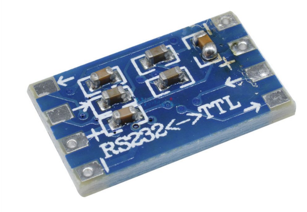
The sad part is that this is a picture of an advertisement of one of those 15 cent converters ads on Aliexpress.... In this case the converter would actually work, since the cap with the bad connection is the power supply bypass... So their "quality control" would not even notice it in a functional test..
-
@TonyMac32 Thanks for verifying it :-) . It did strike me as odd if FA would have overlooked this termination requirement... Also I would have expected network throughput issues because of it, but I couldn't find reports about that... So that made it almost certain that the termination was happening on the die.
-
Fix a damage SD card
in Off-topic
Posted
@Thomasmas How is your answer applicable to armbian? The SD card written with Etcher is 99% sure not a (Ex)FAT formatted card...